Structural Design of 38m Special Purpose Vessel in Aluminium Alloy By Murat Tosun
|
|
|
- Merry Lawson
- 5 years ago
- Views:
Transcription


1 Structural Design of 38m Special Purpose Vessel in Aluminium Alloy By Murat Tosun Supervisor: Prof. Dario Boote, University of Genoa Reviewer: Prof. André Hage, University of Liege
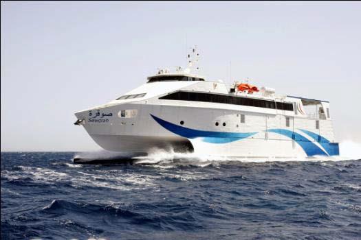


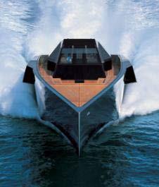

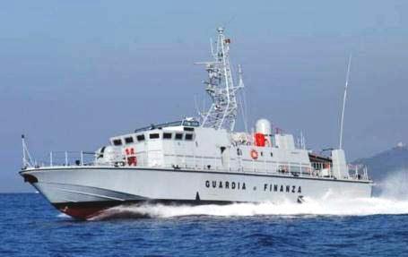
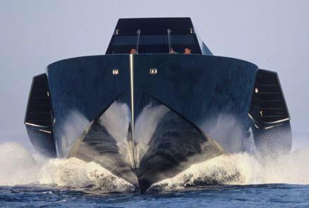
2 Intermarine & Rodriquez Group Fast Ferries Mega Yachts Military Vessels
 Load Capacity Passengers 40 technical Deck cargo 40 t with a maximum height of the CG of 1,2 m from cargo deck Cargo area 60 m 2 (max 1,5 tonne/m 2 ) Weight")
3 Main Dimensions Length overall 38,4 meters Breadth overall 8,6 meters Moulded depth 3,95 meters Gross Tonnage 295 Project Description Propulsion Main Engines 3 x Cummins KTA 50 M2; rpm Propellers 3 x 4 blade (fixed pitch) Load Capacity Passengers 40 technical Deck cargo 40 t with a maximum height of the CG of 1,2 m from cargo deck Cargo area 60 m 2 (max 1,5 tonne/m 2 ) Weight distributed on deck 1,5 tonne/m 2 for loading area and 1,0 tonne/m 2 for remaining areas Deadweight 134 tonnes (difference between the displacement at full load and Lightship) Service Performance Max. speed (@100% RPM) 26 knots Min. speed (@90% RPM) 23 knots
4 Preliminary Design Process Hull Design Local Direct Analyses Capacity Plan Structure Weight Control General Arrangement Stability Analysis Structure Design by Rules Hull Resistance Prediction Freeboard & Gross Tonnage Check
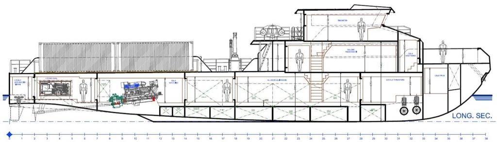

5 General Arrangement Design by A. Battistini

6 Lines Plan Classification Registry: Registro Italiano Navale RINA Class Notation: RINA C, Special Service - Light Ship, Special Navigation - International Operations with Service within 100 miles from shore Flag: Italian
![Tank Arrangement & Capacity Plan Tank Name Intact Permeability Damage Permeability Fluid Type Volume Specific Gravity Weight % % [m 3 ]](/docs-images/89/100343594/images/7-0.jpg "[kg/m 3 ] [kg] Rig water 98 95 Rig water 45,17 1,00 45,17 Gasoil 98 95 Gasoil 43,00 0,8524 36,65 Daily oil 98 95 Gasoil 6,42 0,8524 5,47")

7 Tank Arrangement & Capacity Plan Tank Name Intact Permeability Damage Permeability Fluid Type Volume Specific Gravity Weight % % [m 3 ] [kg/m 3 ] [kg] Rig water Rig water 45,17 1,00 45,17 Gasoil Gasoil 43,00 0, ,65 Daily oil Gasoil 6,42 0,8524 5,47 Overflow Gasoil 1,34 0,8524 1,14 Sludge Sludge 1,34 1,00 1,34 Lubricating oil Lube Oil 0,95 0,92 0,87 Bilge Bilge 2,97 1,00 2,97 Fresh water Black water Grey water Fresh Water Black water Grey water 6,71 1,00 6,71 1,69 1,00 1,69 1,69 1,00 1,69
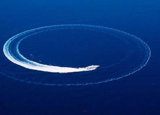
8 Stability Design Criteria Criteria (Full load condition) Value Units Actual Status Margin % : Area 0 to 30 shall not be less than (>=) m.rad 0.34 Pass : Area 0 to 40 shall not be less than (>=) 0.09 m.rad 0.52 Pass : Area 30 to 40 shall not be less than (>=) 0.03 m.rad 0.18 Pass : Max GZ at 30 or greater shall not be less than (>=) 0.20 m 1.05 Pass : Maximum GZ angle shall not be less than (>=) deg Pass : Initial GMt shall not be less than (>=) 0.15 m 3.03 Pass : Passenger crowding angle of equilibrium shall not be greater than (<=) deg 0.80 Pass : Turn angle of equilibrium shall not be greater than (<=) deg 3.40 Pass : Severe wind and rolling criterion: Area 1 / Area 2 shall not be less than (>=) % Pass 58.03
9 Hull Resistance Prediction Hull shape: Hard chine hull in pre-planing regime (1,0 < Fn V < 3,0). In this speed range the dynamic lift begins to have some effects, but has still a modest entity. Speed range: The resistance prediction algorithms are useful only within certain speed ranges; these limits are: Algorithm Low speed limit Actual (For trial condition) High speed limit Savitsky (pre-planing) Fn V = 1,0 1,86 Fn V = 2,0 Savitsky (planing) Fn b = 1,0 1,51 - Lahtiharju (hard chine) Fn V = 1,5 1,86 Fn V = 5,0 Holtrop Fn L = 0,0 0,70 Fn L = 0,8 Dimension limits for Savitsky algorithm: Total resistance for Savitsky pre-planing method: Dimensions Minimum Actual (For trial condition) Maximum L/(V^1/3) 3,07 6,90 12,40 ie 3,70 15,78 28,60 L/B 2,52 4,53 28,26 B/T 1,70 4,94 9,80 At/Ax 0 0,37 1 LCG/L -0,016 0,062 0,066 R T R Cor R App R Air Total resistance; either expressed as: R T = R R + R F + R Cor + R App + R Air or R T = R W + R V + R Cor + R App + R Air Correlation allowance resistance; additional resistance for correlation from model to ship scale Appendage resistance; resistance of appendages such as rudder, etc. Air resistance; wind resistance of above-water hull and superstructure Trial Condition Arrival Condition Half-Load Condition Full-Load Condition Speed Resistance Power Res. Power Res. Power Res. Power [kn] [kn] [kw] [kn] [kw] [kn] [kw] [kn] [kw] 23,0 114, ,72 119, ,34 154, ,71 219, ,34 26,0 127, ,93 133, ,42 171, ,34 239, ,44

10 Computational Fluid Dynamics Analysis Data from Savitsky Method Data from CFD Difference Speed Trim Disp. RT Aft draft Trim Disp. RT Disp. RT [kn] [deg] [tonnes] [kn] [m] [deg] [tonnes] [kn] [%] [%] 26 0,4 157,3 127,92 1,55 0,25 171,37 133,81 8,21 4, ,4 157,3 127,92 1,50 0,25 153,23 112,86-2,65-13, ,4 157,3 127,92 1,53 0,28 155,32 111,84-1,27-14, ,4 157,3 127,92 1,52 0,30 153,62 110,35-2,40-15, ,4 157,3 127,92 1,53 0,30 154,88 110,09-1,56-16, ,4 157,3 127,92 1,55 0,40 165,90 127,24 5,19-0, ,4 157,3 127,92 1,65 1,00 165,93 115,03 5,17-11, ,4 157,3 127,92 1,63 1,00 162,10 113,01 2,93-13, ,4 157,3 127,92 1,63 1,00 158,00 109,30 0,41-17,07
11 Minimum Scanling Requirements Structure Design by Rules 1 Materials 2 Design Acceleration Overall Loads 3 Local Loads 4 The structural elements of the vessel are determined with the rules and regulations of RINA Rules for the Classification of High-Speed Craft. Plates Profiles Filler material 5083 series aluminum alloy 5083 & 6082 series aluminum alloy 5183 series aluminum alloy Plating Thicknesses Ordinary Stiffeners Primary Supporting Members Pillars Main Machinery Seatings Buckling Strength Control Direct Analysis Dimension Value Unit L 36,91 m B 8,60 m B W 8,15 m D 3,95 m T 2,09 m Δ 263,8 tonnes C B 0,41 V 26,00 knots g 9,81 m/s 2 LCG 16,22 m

12 Structure Design by Rules

13 Structure Design by Rules
14 Structure Design by Rules

 tip clearance Longitudinal placement of propeller within the tunnel Longitudinal distribution of")
15 Propeller Pockets Design Tunnels which are also called as propeller pockets are provided in ship hulls to accommodate propellers under reduced draught conditions, thereby avoiding reduction of propeller diameter and consequent loss of efficiency. Main design parameters: Shaft angle (Target is to achieve 6 from 8-9 ) Tunnel depth Propeller (1.28m diameter; 4-bladed) tip clearance Longitudinal placement of propeller within the tunnel Longitudinal distribution of cross-sectional area in the tunnel exit
![PROFILES PLATINGS Structure Weight Thickness [mm] Plate area [m 2 ] Weight [kg] 5 (H321-5083 series aluminum alloy) 880 11703 6 (H321-5083 series aluminum alloy) 363 5793 7 (H321-5083 series aluminum](/docs-images/89/100343594/images/16-0.jpg "alloy) 394 7331 10 (H321-5083 series aluminum alloy) 534 14215 12 (H321-5083 series aluminum alloy) 44 1389 15 (H321-5083 series aluminum alloy) 32 1261 25 (H321-5083 series aluminum alloy) 6 399")
16 PROFILES PLATINGS Structure Weight Thickness [mm] Plate area [m 2 ] Weight [kg] 5 (H series aluminum alloy) (H series aluminum alloy) (H series aluminum alloy) (H series aluminum alloy) (H series aluminum alloy) (H series aluminum alloy) (H series aluminum alloy) Typical Profile Length [m] Weight [kg] 60x40x5 (H series aluminum alloy) x60x4 (H series aluminum alloy) x5+50x7 (H series aluminum alloy) x5+50x9 (H series aluminum alloy) Ø100x10 (T series aluminum alloy) SUBTOTAL Welding 5183 series aluminum alloy 3% 1442 TOTAL 49517

17 Structural Strength Analysis by FEM Objective & Scope Main machinery foundations of the hull are investigated in detail for the structural analysis of the craft to ensure continuity of the reinforced elements Finite Element Model Below figure presents FE model with given different thicknesses. There are 6 main girders for 3 engines and center engine girders are connected to lubricating oil tank and this tank is situated by the side of sea chest Direct Analysis Procedures Structural finite element (FE) model development Specification of the load cases Determining of boundary conditions Strength analysis Application of the checking criteria


18 Structural Strength Analysis by FEM Loading Condition in Still Water Forces caused by engine weights and pillars through standard earth gravity Outer hydrostatic load in still water Combined Loading Condition Forces of inertia due to the vertical acceleration a v of the craft, considered in a downward direction Forces caused by engine weights and pillars through vertical acceleration


19 Structural Strength Analysis by FEM Mesh Model Global mesh is created with following features: Mesh element type: SHELL181 Mesh method: Quadrilateral dominant Element size: 8,6 mm 43 mm Number of elements: Boundary Conditions All longitudinal edges on bulkheads are fixed on X, Y and Z directions, rotations however are permitted


20 Structural Strength Analysis by FEM Loading Condition in Still Water Combined Loading Condition
![Structural Strength Analysis by FEM Checking Criteria Still water loading condition Highest stress [N/mm 2 ] Check [N/mm 2 ] Safety factor Normal stress 17,30 69,77 4,03 Shear stress 8,56 41,86 4,89](/docs-images/89/100343594/images/21-0.jpg "Von-Mises equivalent bending stress 32,29 88,37 2,74 Combined loading condition Highest stress [N/mm 2 ] Check [N/mm 2 ] Safety factor Normal stress 24,94 87,21 3,49 Shear stress 8,15 52,33 6,42")
21 Structural Strength Analysis by FEM Checking Criteria Still water loading condition Highest stress [N/mm 2 ] Check [N/mm 2 ] Safety factor Normal stress 17,30 69,77 4,03 Shear stress 8,56 41,86 4,89 Von-Mises equivalent bending stress 32,29 88,37 2,74 Combined loading condition Highest stress [N/mm 2 ] Check [N/mm 2 ] Safety factor Normal stress 24,94 87,21 3,49 Shear stress 8,15 52,33 6,42 Von-Mises equivalent bending stress 36,06 110,47 3,06
22 Conclusions The hull resistance prediction is essentially momentous for developing hull lines at preliminary design stages. For this purpose Savitsky Method is applied primarily, then more accurate results are obtained by CFD applications and these results are compared with previous method. Meanwhile spray flow over the hull is observed even the resistance values are in a good range. To prevent this, using of spray rails under the chine is proposed. Although the vessel is a high speed craft, it will work as a supply unit for offshore platforms to transport technical personnel, cargo on deck and liquid cargo. On the other hand, the structure design is developed according to High Speed Craft rules by directives of Classification Society. In compliance with experiences of the shipyard, total structure weight, 50 tonnes, satisfied the predictions. By considering experimental studies and recommendations of suppliers, partial tunnels are created under the hull and eventually shaft line angle is reduced 3 approximately. Direct finite element analysis of engine foundations which have significant influence on structure is performed. Eventually high safety margins are gained for the scantling which is generated on the strength of previous projects of the shipyard.

23 Thank you for your attention!