Arc Welding. ROOP LAL Unit-6 (Arc Welding) Mechanical Engineering Department. Soft Copy Available at:
|
|
|
- Britton Parsons
- 5 years ago
- Views:
Transcription
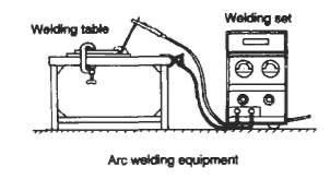
1 Arc Welding 1. Arc Welding: The welding in which the electric arc is produced to give heat for the purpose of joining two surfaces is called electric arc welding. In this the heat of fusion is generated by an electric arc struck between two electrodes, one of which is the work piece. This heat is used to melt the metals to be welded at the points of contact, so that they will flow together and form a joint. Hence, different parts may be joined. A filler material is also added to the surface of the metal. When addition metal is required a welding rod is used as filler material. The welding rod is made of a metal similar to the work piece and is coated with a solid flux which melts and prevents oxidation of the weld. The rod is used to fill the welded joint. Power is obtained from an A.C. or D.C. welding set providing a regulated low-voltage high-current supply to an electrode holder and earthing clamp. The welding is done on a steel welding table to which the work is clamped and to which the earthing clamp is attached to complete the circuit Figure 1: Arc Welding 1

2 1.1 Principle of Arc Welding (Shielded Metal Arc): Power supply is given to electrode and a work. A suitable gap is kept between the work and electrode. A high current is passed through the circuit. An arc is produced around the area to be welded. The electric energy is converted into heat energy, producing a temperature of 3000 o C to 4000 o C. This heat melts the edges to be welded and molten pool is formed. On solidification the welding joint is obtained. Arc initiation voltage range is 60 to 100V and arc maintenance voltage range is 25 to 40V. One electrode is Filler Metal called metal electrode is coated with flux which produces a gas to provide a shield around the arc to protect molten metal from atmosphere oxidation. Thereby this process is also called Shielded Metal Arc Welding. Figure 1.1 : Electric Arc Welding Apparatus Electric Power for Welding: AC current or DC current can be used for arc welding. For most purposes, DC current is preferred. In DC welding, a DC generator or a solid state rectifier is used. DC machines are available up to the capacity range 600 amperes. The voltage in open circuit is kept 45 to 100 volts and in close circuit, 15 to 25 volts. DC Current can be given in two ways: (a) Straight polarity Welding : In the Straight polarity Welding work piece is made anode and the electrode is made cathode as shown in the figure, Electrons flows from cathode to anode thus heat is produced at the work pieces to be welded. Fig 1.1(a): Straight polarity welding 2
3 (b) Reverse polarity Welding: In the reverse polarity Welding work piece is made cathode and the electrode is made anode as shown in the figure. This welding is done specially for thin section Fig1.1(b) : Reverse polarity Welding AC welding has the advantage of being cheap. Equipment used is simpler than those used in DC welding. A transformer is used to increase the current output at the electrode. The current vary from 150 to 1000 amperes depending upon the type of work. An AC Arc welding circuit is shown in the figure. Fig 1.1(c): AC Arc welding circuit Arc Welding Processes (i) Manual metal arc (ii) Carbon arc Welding (iii) Submerged arc (iv) Tungsten inert gas (TIG) (v) Metal inert gas (MIG) (vi) Open arc, automatic (vii) Atomic hydrogen (viii) Arc stud welding (ix) Spot welding (x) Spot welding (xi) Projection welding (xii) Electro slag (xiii) Thermit Welding (xiv) Laser welding (xv) Plasma welding (xvi) Electron beam welding 1.2 Carbon Arc Welding: This is Arc Welding process. In this process DC current is used. Negative terminal of supply is connected to the Carbon electrode and the positive terminal is connected to the work piece. 2/3 of the total heat produced, will be at the positive terminal hence work is made positive terminal. Less heat will be produced on the negative terminal preventing carbon content of electrode being carried over to job. Flux is used to prevent the weld metal from picking up carbon from the fused electrode. A separate filler rod is used for supplying molten metal for the weld. Remaining process is similar to the arc welding. 3

4 1.3 Submerged arc Welding (SAW): This process is for welding thicker steel plates. It produces high quality butt joint. In this process a consumable bare filler rod is used in combination with a granular flux feeder tube which takes its supply from a feeder hopper. This granular flux is placed along the seam to be weld. The flux is used freely and an arc is maintained under a blanket of flux. The feed of the electrode and flux tube is automatic. The entire process of welding take place beneath the granular flux material. Hence this process is called as Submerged Arc Welding. The arc is started either by striking beneath the flux on the work or initially by placing some conductive medium. The intense heat of the arc produces a pool of molten metal in the joint and at the same time melts portion of flux. Molten flux forms a protective coating of slag over the weld thereby protects the welded joint from oxidation. Upon cooling, the fused slag solidifies and removed. The use of high current of the order of 300 to 4000 amperes permits higher welding speeds than in other processes. Since the melt is composed mostly of base metal, the finished weld resembles the base metal and makes for homogeneous structure. The granular flux material not fused can be reused again. Steel plates up to 12 mm can be welded. This process is applicable to low carbon and alloy steels, some time non ferrous metals are also welded. Fig. 1.3: Submerged arc welding 4
5 The major advantages of the SAW or submerged arc welding process are: 1. High quality metal weld. 2. Extremely high speed and deposition rate 3. Smooth, uniform finished weld with no spatter. 4. Little or no smoke. 5. No arc flash, thus minimal need for protective clothing. 6. High utilization of electrode wire. 7. Easy automation for high-operator factor. 8. Normally, no involvement of manipulative skills. 1.4 Tungsten inert gas (TIG): it is an arc welding process in which the arc is struck between a non consumable tungsten electrode and the base metal. Electrode is held in a special type of electrode holder which is designed not only to hold electrode but also carries a passage around the electrode for flow of inert gas which provide the protective shield around the arc. Supply of inert gas around the electrode that creates an inert atmosphere around the arc protect the electrode, molten metal the arc and adjacent hot area of the base metal from oxidation. Electrode holder is also have a provision for water cooling or air cooling. Hence cooling during welding is done by the electrode holder by supply of water or air. It is the process can produce continuous, intermittent or spot weld. Since electrode is non consumable, it does not provide filler metal. A separate filler metal rod is needed as in the case of gas welding. This process is suitable for all metals except lead and zinc. TIG Welding Equipments: a) Welding bench b) Electrode holder c) Welding machine d) Inert gas cylinder e) Cooling Water or air supply f) Gas hoses g) Tungsten electrode h) Filler rods i) Inert gas regulator and flow meter fitted on gas cylinder j) Eye shield Welding Current: AC or DC may be used in TIG Welding. AC enables good penetration and less surface oxidation. DC with straight polarity is less preferred as it provides less penetration and need high skilled operators. TIG welding Procedure: a) Clean the joint area thoroughly for any dirt, oil or grease etc. b) Hold the work pieces in the suitable fixture properly. c) Select the suitable size of electrode and hold it in the electrode holder. 5
6 d) Set the current and proper polarity in case of DC. e) Turn on the cooling water or air supply. f) Turn on the inert gas supply and adjust its flow rate. g) Switch on the power supply. h) Strike the arc, make a small puddle of molten metal at the welding point using a very small circular motion of the electrode. Hold the electrode at an angle of 60o to 80o and the filler rod at 15o to 20o with the work piece. i) Then proceed welding in the similar fashion as in the gas welding. j) After completion of weld, lift the electrode holder quickly to break arc. k) Switch of the current flow with the help of foot pedal. l) Allow the inert gas to flow until the electrode is cools down. Fig.1.4: Tungsten inert gas (TIG) 6

7 1.5 Metal Inert Gas Welding (MIG): This is welding process in which a consumable electrode is fed through the electrode holder into the arc, at the speed at which electrode melts and deposit in the weld. Consumable electrode, in the form of wire, wound on the reel, is moved by a adjustable speed small motor. CO2 or argon or their mixture or helium is normally used as shielding gas for welding various types of carbon steels. but CO2 is more widely used. A specially designed electrode holder is used which in addition to a passage for wire electrode, also supply of inert gas around the electrode that creates an inert atmosphere around the arc protect the electrode, molten metal the arc and adjacent hot area of the base metal from oxidation. It also has the provision for supply of cooling water. Normally DC with reverse polarity is used in MIG Welding. AC is not used in this method. DC with reverse polarity enable a deeper penetration and a clean weld surface Figure 1.5: Metal Inert Gas Welding 7
 Gas hoses and connections c) Power supply source d) MIG welding electrode holder e) Reel of electrode wire f) Electrode wire feeder motor g) Cooling water supply with water hoses h) Control system")
8 Figure 1.5(b): Shielded Arc welding Metal Inert Gas Welding Equipments: a) Inert gas cylinder with gas regulator and flow meter. b) Gas hoses and connections c) Power supply source d) MIG welding electrode holder e) Reel of electrode wire f) Electrode wire feeder motor g) Cooling water supply with water hoses h) Control system i) Welding Machine Metal Inert Gas Welding methods: Two principal MIG welding methods are: 1. Spray Arc Method: In the spray arc welding, the metal is transferred across the arc as a fine spray of minute droplets. This method is used mainly on good fit joints and faster welding. In this method heavy current flow for certain size electrode wire is used, so that the electrode wire divides in to small droplets and travel forcibly across the arc to the joint without interfering the stability of arc.. 2. Dip Transfer Method: It is also known as Short Circuit Method. In this method, filler metal is melted from the electrode in the form of large drops which touch the base metal before separating from the electrode. In this process of separation, arc is short circuited momentarily and as soon as the drop is separated, a proper gap between the electrode tip and the base metal obtained, arc is restored. This method is used for poor fit up joints and thin sections Advantages of Metal Inert Gas Welding: 1. No slag formation 2. Faster welding process 3. Deeper penetration possible 4. Thin sheets can be welded 5. Better quality welds 6. Faster rate of deposition 8
9 1.5.4 Disadvantages of Metal Inert Gas Welding: 1. Equipments are costly and non portable 2. Not suitable for outdoor welding because strong wind may carry away the gas shield Atomic Hydrogen Welding: This electrode holder or torch consists of two tubes in an insulated handle, through which both hydrogen gas and electric current flow. The hydrogen is supplied to a tube in the rear of the handle from which it is led into the two current carrying tubes by means of a manifold. One of the two electrode holders is movable, and the gap between this and the other holder is adjusted by means of a trigger on the handle Figure 1.5.5: Atomic Hydrogen Welding Torch 1.6 Thermit Welding: In this process of welding, exothermic chemical reaction is employed for producing a high temperature. It is a fusion welding process in which weld is made by pouring super heated liquid metal around the parts to be joined. The heat of thermit reaction is used to raise the temperature of metal surfaces to be welded to plastic state and then mechanical pressure is applied to complete the weld. Thermit reaction take place between finely divided aluminium and iron oxide. Three parts of iron oxide and eight parts of aluminium take part in the reaction. Reaction is represented by the following chemical equation: 8Al + 3 Fe3O4 9Fe + 4Al2O3 + Heat During the reaction a very high temperature of the order of 2700 o C is developed. This temperature is sufficient to melt the steel. The reaction is non explosive take 30 seconds to complete. Initial temperature of 1100 o C is needed for ignition. Usually Barium peroxide powder is used for igniting the thermit mixture. In this process of pressure welding, a wax pattern is prepared arount the parts to be welded. Around this pattern a sheet box is placed and the space between the box and 9

10 pattern is filled with sand then sand is rammed. Pouring, heating and riser gates are cut in the sand. A gas flame is used to pre heat the parts to be welded and melt the wax pattern. Preheating is done to prevent the chilling effect of steel when liquid metal is poured. Then the flame is removed and the heating gate is plugged. The superheated steel from crucible is poured into the mould surrounding the surface to be welded. When welding temperature is reached, mechanical pressure is applied to complete the weld. Application of Thermit Welding: 1. Repair of heavy parts such as railway tracks. 2. Repair of Broken castings. 3. Repair of Broken connecting rods 4. Welding of pipes. Figure 1.6: Thermit Welding Note: The thermit mixture is kept dry, because wet or damp mixture can not be restored to original state. Advantages: 1. This welding process is applicable to repair large sections. 10

11 2. Broken parts can be repaired in their place. 3. Tensile strength of thermit welded joints is 5000 kg/cm2> 4. Yield strength is about 2500 kg/cm2 5. Elongation from 35% to zero. Plasma Arc Welding: 2. Equipments used for Arc welding: Various Equipments used for Arc welding are: 1. DC Welding Equipments: a. AC Motor Generator Set b. Diesel Engine - Generator Set c. Transformer Rectifier Welding Set 2. AC Equipments a. Welding Transformer Set 3. Accessories: 11

12 a. Leads b. Holders c. Connectors d. Ground Clamps 4. Operators Tool: a. Chipping Hammer b. Wire Brush c. Arc Shield d. Closed Shoe AC Motor Generator: In this a generator is driven by a suitable AC motor. The average voltage of the generator is 25 volt. The current range is 25 to 100 amperes, the voltage is variable and can be set to the desired value with the help of rheostat. Diesel Engine Generator Set: In this a generator is driven by a Diesel engine. The rest of the system is same in case of AC motor generator. Diesel engine generator sets are used in the areas where electricity is not available. Transformer Rectifier Set: It allows the current to flow through it only one direction. It has a one way solid rectifier installed on the electrode side of the secondary coil. Set can supply straight polarity and reverse polarity power supply. The rectifiers are of two types: i. Silicon Diode ii. Selenium plate Fig.2: Transformer Rectifier Set 2.1 Welding Transformer Set: It is used to step down the voltage supply. It consists of a primary and secondary circuit. The input is given to primary winding. By electromagnetic induction the current flows through the secondary coil. The output can be controlled as per requirement 12

13 Fig. 2.1: Welding Transformer Set 13
14 Cables or Leads: These leads are made of copper or aluminium wires with a heavy insulation of rubber and cloth fibre. Face Shield: When arc is produced around the job, infrared rays and ultraviolet rays are produced. To protect the face and eyes from these rays, a shield is used Other Accessories and Tools: Other Accessories and Tools used for arc welding are shown below in figures: Starting an Arc: Producing an arc between the electrode and work is important aspect for beginners and needs some practice. The best method is to touch the electrode with work and then lift it up to the desired arc length. Arc length is the distance from the top of electrode to the bottom of the arc. It vary from 2 to 4 mm. In short arc length the time of contact will be shorter and will make a wide and shallow bead. The penetration is low as compared to long arc length. Another method of starting the arc is by producing glancing or scratching motion with the end of the electrode, moving the electrode in arc by mm. it may be noted that it is easier to start DC arc than AC arc because of the tendency of the apparatus to break the arc on the change of cycle 3. Resistance Welding: It is the process of joining two metal pieces together. In this process metal pieces to be joined are held together and AC current of high amperage and low voltage is passed through them. While this current passing from one piece to another piece, it come across air resistance existing between two pieces. This resistance causes rise in the temperature in the localized area according to The principle which is based on resistance and heat produced h = I 2 RT, where I = current, R = resistance and T 14
15 = time of current passage. When the temperature is risen above fusion temperature, External pressure is allied by a lever fixed in the lower portion of the machine with the help of foot. This pressure help in fusing the two pieces together, then foot pressure is removed, thus weld is formed. Resistance welding is further subdivided into : a) Spot Welding b) Seam Welding c) Butt Welding d) Flash Welding e) Projection Welding f) Percussion Welding 3.1 Spot Welding: It is a method used for making Lap welds for sheets up to 13 mm thickness. It consists of a transformer having primary and secondary windings. There are two arms, first is a movable arm E1 and other is fixed arm E2, both connected to secondary coil of the transformer. Two sheets S1 and S2 to be joined are placed between the two arms as shown in fig.16. Then a supply of high amperage and low voltage is supplied between the two sheets. Pressure is also exerted by the fixed and the movable arm. Due to passage of supply, heat is produced, which bring the adjoining surface to the melting point, then it is joined due to external pressure. This principle is based on resistance welding and heat produced = I 2 RT, where I = current, R = resistance and T = time of current passage. External pressure is allied by a lever fixed in the lower portion of the machine and operated by foot. Fig. 3.1: Spot Welding Machine 15
16 3.2 Seam Welding: The principle of seam welding is same as that of a spot welding, only difference that the tips of the spot welding is replaced by rotating wheels as shown below. As a result of wheels a continuous welding is obtained where as in case of spot welding we get intermittent welds. Fig 3.2: Seam Welding In this process, two sheet is fed between the two rotating wheels that acts as electrodes, a supply of high current and low voltage is maintained between the electrodes. It is very fast welding process and strength of joint obtained by seam welding is more. Here before welding, the surfaces to be joined are cleaned by brush. Projection Welding: 4. Welding Positions: In horizontal position it is very easy to weld. But many times it is impossible to weld the job in horizontal position. Possible welding positions are: a. Flat Position: In flat Position the work is kept in horizontal position. The surface to be welded is kept on upper side. Welding is done as shown in following figure: 16
17 b. Horizontal Position: In this position two surfaces rest one over the other with their flat faces in vertical plane. Welding is done from right side to left side. The axis of the weld is in a horizontal plane and its face in vertical plane. c. Vertical position : In this position the axis of the weld remains in approximately in vertical plane. The welding is started at the bottom and proceeds towards top. The welding process is illustrated in following figure. d. Overhead Position: In this Work piece remains over the head of the welder. The work piece and the axis of the weld remains in horizontal plane. It is most difficult position of welding. 5. Electrodes: Electrodes used in Arc welding are of two types: i. Coated Electrodes : Coated Electrodes are generally applied in arc welding processes. A metallic core is coated with some suitable material. The material used for core is mild steel, nickel steel, etc. One end of the coated core is kept bare for holding. ii. Bare Electrodes: Bare Electrodes produce the welding of poor quality. These are cheaper than coated electrodes. These are generally used in modern welding process like MIG welding. Sizes of Electrodes: Lengths : 250mm, 300mm, 350 mm, and 450 mm Diameters : 1.6 mm, 2 mm, 2.5 mm, 3.2 mm, 4 mm, 7 mm, 8 mm and 9 mm. 6. Functions of Flux Coatings: There are following functions of flux coatings on an electrode: a. It produces a gas which provides a shield around the arc to prevent oxidation of molten metal. b. Form slags by mixing with molten metal impurities thus refines the metal. c. It helps in stabilizing the arc d. Controls depth of penetration e. Controls the cooling rate. f. Increases deposition of molten metal g. Some time is also adds alloy elements to the joint 7. Electrodes Specifications: An Electrode is specified by six digits with letter M as prefix: M : It shows that it is suitable for metal arc welding. First Digit: First Digit is from 1 to 8, indicates the type of coating on the electrode. Second Digit: Second Digit is from 1 to 6, It denotes the welding position for which electrode is manufactured. 17
18 Third Digit: Third Digit is from 0 to 7, denotes the current to be used for electrode. Fourth Digit: Fourth Digit is from 1 to 8, represents the tensile strength of welded joint. Fifth Digit: Fifth Digit is from 1 to 5, denotes specific elongation in percentage of the metal deposited. Sixth Digit: Sixth Digit is from 1 to 5, denotes the impact strength of the joint. 8. Comparison Between AC and DC Welding: Sl. No. AC Welding DC Welding 1. Equipments are simpler and cheaper Equipments are complicated and costlier AC transfer is easy to maintain due to absence of moving parts Due to low voltage drop, it can be operated at large distance from power source Less problem of arc blow Only coated electrodes are used It can be used for welding ferrous metal only It can be used when AC current is available DC Generator has many moving parts due which its maintenance is costlier In DC voltage drop is high. Therefore shorter cables are used. More problem of arc blow Both coated and bare electrodes are used It can be used for welding almost all metals In case of non availability of AC supply, an engine generator can be used. 18