High Performance Catalog
|
|
|
- Kristian Rodgers
- 5 years ago
- Views:
Transcription


1 High Performance Catalog


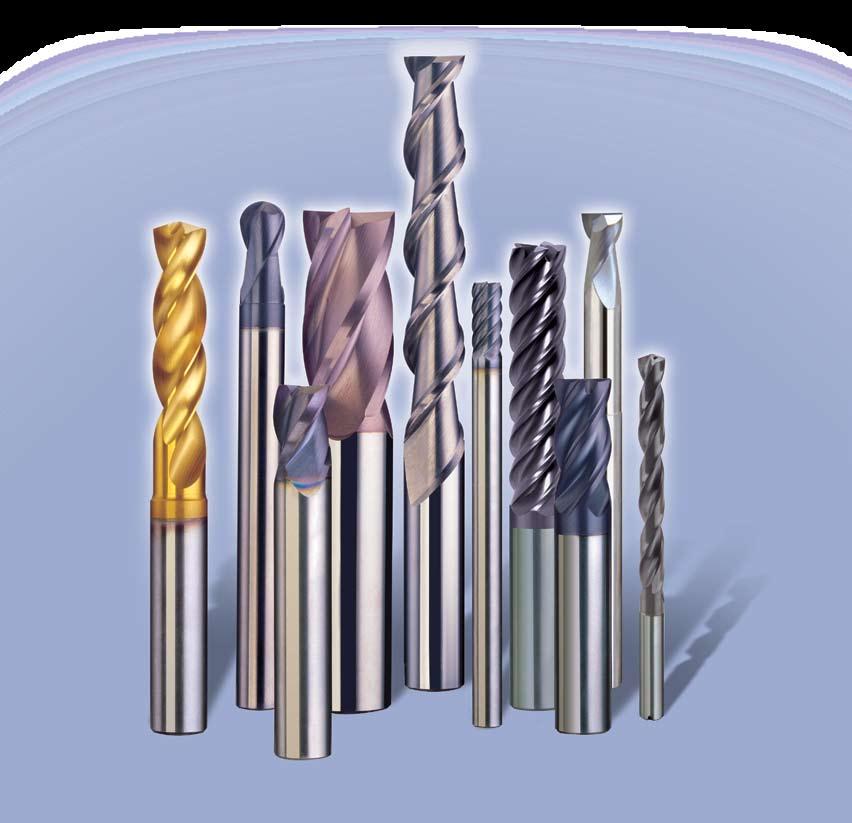
2 As a technological leader, SGS Tool Company is committed to provide you with leading-edge, high-performance products. We address the complexities of High-Speed Machining with particular focus upon Aerospace, Automotive, Mold & Die, and Production Machining Applications. Extensive product testing has shown that SGS High Performance Tools can increase productivity rates many times over conventional carbide end mills and drills. The experience we acquire from designing and manufacturing these high-performance products has a positive impact upon every standard and special application tool we produce. High Performance Solid Carbide Tools The Finishing Touch best describes the V-Carb 5 Flute End Mills. The unique geometry and corner radii allows this tool to produce exceptional results in finish and semi-finish milling applications. V-Carb has also performed well in heavy peripheral and slotting applications. A quiet giant, the patented Z-Carb 4 Flute End Mills have revolutionized milling of ferrous materials with it s unequal helix geometry design. Z-Carb has been recorded to improve productivity up to 30 times over conventional 4-flute end mills and has achieved a 100% increase in radial width of cut. SGS Industry Applications Icon Key and Matrix Throughout the SGS Tool Company High Performance Catalog, you ll find icons indicating for which industry applications SGS High Performance products are best suited. Mold & Die Automotive Aerospace Power Generation Castings & Foundries Z-Carb V-Carb Tri-Carb Turbo-Carb Power-Carb Ski-Carb S-Carb ICe-Carb Hi-PerCarb The Performance of SGS Solid Carbide, Rotary Cutting Tools can be enhanced in many applications with our specially developed Ti NAMITE PVD Process Tool Coatings. These proprietary processes result in not only maximum tool life, but also faster cutting speeds and reduction of edge wear. Ti-NAMITE Tool Coatings are developed and processed at our own multimillion dollar facility in Munroe Falls, Ohio USA. Dia-Carb SGS HIGH PERFORMANCE


3 Table of Contents Z CARB End Mills for Ferrous Applications Series Z1, Z1B, Z1CR, Z1CR-Specific Corner Radius Series Z1LC, Z1LB, Z16CR, Z1M, Z1MCR, Z1MB Z-CARB HTA Series ZH1CR, ZH1MCR JetStream Z-Carb End Mills V-CARB 5 Flute End Mills for Finishing and Semi-Finishing Series 55CR, 55, 55M TRI-CARB 3 Flute End Mills for Roughing and Semi-Roughing Series 65 and 65M TURBO-CARB End Mills for Hardened Mold & Die Steels Series 56B and 56MB POWER-CARB End Mills for Mold Grade Steels up to 65Rc Series 57 and 57M SKI-CARB End Mills for Aluminum and Non-Ferrous Applications Series 44, 45 and 44M S-CARB Solid Carbide End Mills for Aluminum Series 47, 47B, 47ES, 47EB, 47M, 47MB 47MES, 47MEB ICe-Carb Internal Coolant Drills Series 140M HI-PERCARB Drills Series 135, 135M and 135L DIA-CARB Diamond Coating TM Amorphous Diamond Coated End Mills Series 1, 1L, 1EL, 1B, 1LB, 1ELB CVD Diamond Coated End Mills Series 1, 1B, 3, 3B Ti-NAMITE Tool Coatings


4 Chatter-Resistant Design: Improves Surface Finish Optimum Material Removal: Increases Cutting Depth Increases Feed Rates Increased Tool Life: Ti-NAMITE-A (AlTiN Coated) Corner Radius Special Gash Break Out Grind Eccentric Relief Minimum Tool Deflection: Reduces HarmfulMachine Vibration Improves Dimensional Control Material Applications Include: Low Carbon Steels Tool Steels Cast Iron Stainless Steels Titanium/High Temp Alloys Revolutionizes Milling Patented Unequal Helix Geometry DESIGN BENEFITS The Z CARB end mill maximizes stock removal and improves productivity in most milling operations. Chatter is the most common problem associated with aggressive milling. The SGS Z CARB design features reduce chatter, increase tool life and optimize performance. Z CARB tools are coated with SGS Ti- NAMITE-A coating that resists heat generated in aggressive cutting operations. APPLICATION TIPS Tool holders with adequate gripping pressure are required Stub length solid holders are recommended for heavy stock removal Avoid remilling chips Ramping or spiral plunging are the preferred entry methods into pockets (approximately 6 at 50 % normal feed) Regrind and recondition services are available from SGS Set-up rigidity critical during heavy roughing PATENT NUMBERS: U.S.: 4,963,059 Germany: 3,706,282 Korea: 065,154 Japan: SGS HIGH PERFORMANCE
5 Fractional d 1 d 2 Z CARB Series Z1 4 Flute - Square End Cutting Length Overall Shank Ti-NAMITE-A (AlTiN) Diameter of Cut Length Diameter EDP No. EDP No. d 1 d 2 w/ flat 1/8 3/8 1-1/2 1/ /32 7/16 2 3/ /16 7/16 2 3/ /32 7/16 2-1/2 1/ /4 1/2 2-1/2 1/ /32 5/8 2-1/2 5/ /16 13/16 2-1/2 5/ /32 13/16 2-1/2 3/ /8 7/8 2-1/2 3/ /32 15/16 2-3/4 7/ / /4 7/ / / / / /16 1-1/8 3-1/2 9/ /8 1-1/4 3-1/2 5/ /4 1-1/2 4 3/ / d 1 d 2 Z CARB Series Z1B 4 Flute - Ball End Cutting Length Overall Shank Ti-NAMITE-A (AlTiN) Diameter of Cut Length Diameter EDP No. EDP No. d 1 d 2 w/ flat 1/8 3/8 1-1/2 1/ /32 7/16 2 3/ /16 7/16 2 3/ /32 7/16 2-1/2 1/ /4 1/2 2-1/2 1/ /32 5/8 2-1/2 5/ /16 13/16 2-1/2 5/ /32 13/16 2-1/2 3/ /8 7/8 2-1/2 3/ /32 15/16 2-3/4 7/ / /4 7/ / / / / /16 1-1/8 3-1/2 9/ /8 1-1/4 3-1/2 5/ /4 1-1/2 4 3/ / Tolerances (inch) Diameter d 1 d 2 1/8 1/ / /.0003 > 1/4 3/ / /.0003 > 3/ / /.0004 d 1 d 2 Z CARB Series Z1CR 4 Flute - Corner Radius Cutting Length Overall Shank Corner Ti-NAMITE-A (AlTiN) Diameter of Cut Length Diameter Radius EDP No. EDP No. d 1 d 2 w/ flat 1/8 3/8 1-1/2 1/ /16 7/16 2 3/ /4 1/2 2-1/2 1/ /16 13/16 2-1/2 5/ /8 7/8 2-1/2 3/ / /4 7/ / / /16 1-1/8 3-1/2 9/ /8 1-1/4 3-1/2 5/ /4 1-1/2 4 3/ /
6 Fractional d 1 d 2 Z CARB Series Z1CR 4 Flute Specific Corner Radius TiNAMITE-A TiNAMITE-A (AlTiN) (AlTiN) Cutting Length Overall Shank Corner EDP EDP Diameter of Cut Length Diameter Radius Number Number d 1 d 2 w/flat 1/8 3/8 1-1/2 1/ /16 7/16 2 3/ /4 1/2 2-1/2 1/ /4 1/2 2-1/2 1/ /16 13/16 2-1/2 5/ /8 7/8 2-1/2 3/ /8 7/8 2-1/2 3/ / /4 7/ / / / / / / / / /16 1-1/8 3-1/2 9/ /8 1-1/4 3-1/2 5/ /8 1-1/4 3-1/2 5/ /8 1-1/4 3-1/2 5/ /4 1-1/2 4 3/ /4 1-1/2 4 3/ /4 1-1/2 4 3/ /4 1-1/2 4 3/ / / / / d 1 d 2 Z CARB Series Z1LC - 4 Flute Long Reach with Corner Radius Ti-NAMITE-A Cutting Length Overall Shank Corner (AlTiN) Diameter of Cut Length Diameter Radius EDP No. d 1 d 2 1/4 1/2 4 1/ /16 13/16 4 5/ /8 7/8 5 3/ / / / / /16 1-1/8 6 9/ /8 1-1/4 6 5/ /4 1-1/2 6 3/ / Tolerances (inch) Diameter d 1 d 2 1/8 1/ / /.0003 > 1/4 3/ / /.0003 > 3/ / /.0004 SPECIFIC CORNER RADIUS TOLERANCES +.000/ SGS HIGH PERFORMANCE
7 d 1 d 2 d 1 d 2 Fractional Z CARB Series Z1LB - 4 Flute Long Reach Ball End Ti-NAMITE-A Cutting Length Overall Shank (AlTiN) Diameter of Cut Length Diameter EDP No. d 1 d 2 1/4 1/2 4 1/ /16 13/16 4 5/ /8 7/8 5 3/ / / / / /16 1-1/8 6 9/ /8 1-1/4 6 5/ /4 1-1/2 6 3/ / Tolerances (inch) Diameter d 1 d 2 1/8 1/ / /.0003 > 1/4 3/ / /.0003 > 3/ / /.0004 Z CARB Series Z16CR - 4 Flute Short Length with Corner Radius Ti-NAMITE-A Cutting Length Overall Shank Corner (AlTiN) Diameter of Cut Length Diameter Radius EDP No. d 1 d 2 1/8 1/4 1-1/2 1/ /32 5/16 2 3/ /16 3/8 2 3/ /32 3/8 2 1/ /4 7/16 2 1/ /16 1/2 2 5/ /8 5/8 2 3/ /16 5/8 2-1/2 7/ /2 5/8 2-1/2 1/ /8 3/4 3 5/ / / Fractional - Speed and Feed Recommendations CUTTING DIAMETER (d 1) Material Bhn 1/8 3/16 1/4 5/16 3/8 7/16 1/2 5/8 3/4 1 rpm in/min rpm in/min rpm in/min rpm in/min rpm in/min rpm in/min rpm in/min rpm in/min rpm in/min rpm in/min low carbon steels ~175 15, , , , , , , , , , low carbon steels ~275 12, , , , , , , , , , med alloy steels ~275 10, , , , , , , , , , mold and die steels ~275 5, , , , , , , , cast iron - gray ~200 14, , , , , , , , , , cast iron - ductile ~300 7, , , , , , , , , cast iron - malleable ~300 4, , , , , , , stainless 300 series ~275 9, , , , , , , , , , stainless 400 series ~185 12, , , , , , , , , , stainless PH series ~325 7, , , , , , , , , titanium alloys ~295 9, , , , , , , , , , high temp alloys ~300 2, , , Profiling: Radial Width.5 x Diameter (max.) Profiling: Axial Depth 1.5 x Diameter (max.) Slotting: Axial Depth 1 x Diameter (max.) 7
8 d 1 d 2 Z CARB Series Z1MCR - 4 Flute - Corner Radius Metric d 1 d 2 Z CARB Series Z1M - 4 Flute - Square End Ti-NAMITE-A Cutting Length Overall Shank (AlTiN) Diameter of Cut Length Diameter EDP No. d 1 d 2 mm mm mm mm Ti-NAMITE-A Cutting Length Overall Shank Corner (AlTiN) Diameter of Cut Length Diameter Radius EDP No. d 1 d 2 mm mm mm mm ,25-0, ,25-0, ,25-0, ,38-0, ,38-0, ,38-0, ,38-0, ,38-0, ,64-0, ,64-0, ,64-0, ,64-0, ,64-0, , ,89-1, ,89-1, , ,89-1, ,89-1, Z CARB Series Z1MB - 4 Flute - Ball End Ti-NAMITE-A Cutting Length Overall Shank (AlTiN) Diameter of Cut Length Diameter EDP No. d 1 d 2 mm mm mm mm d 1 d 2 Tolerances (mm) Diameter d 1 d ,000/ 0,030 0,0025/ 0,0075 > ,000/ 0,040 0,0025/ 0,0075 > ,000/ 0,050 0,0025/ 0,010 8 SGS HIGH PERFORMANCE

9 Metric - Z-CARB - Speed and Feed Recommendations CUTTING DIAMETER (d 1) Material Bhn rpm mm/min rpm mm/min rpm mm/min rpm mm/min rpm mm/min rpm mm/min low carbon steels ~175 16, , , , , , , low carbon steels ~275 13, , , , , , , med alloy steels ~275 11, , , , , , , mold and die steels ~275 5, , , , , , , cast iron - gray ~200 15, , , , , , , cast iron - ductile ~300 7, , , , , , , cast iron - malleable ~300 4, , , , , , , stainless 300 series ~275 9, , , , , , , stainless 400 series ~185 13, , , , , , , stainless PH series ~325 8, , , , , , , titanium alloys ~295 9, , , , , , , high temp alloys ~300 2, , , rpm mm/min rpm mm/min rpm mm/min rpm mm/min 3, , , , , , , , , , , , , , , , , , , , , , , , , , , , Profiling: Radial Width.5 x Diameter (max.) Profiling: Axial Depth 1.5 x Diameter (max.) Slotting: Axial Depth 1 x Diameter (max.) Axial Depth 1.5 x Diameter (max.) Axial Depth 1.5 x Diameter (max.) 9
 Coating Fractional Z-CARB -HTA Series ZH1CR 4 Flute Fractional")

10 Features and Benefits Maximum Rigidity Provides additional resistance against chipping and breakage Allows higher material removal rates Reduced Cutting Forces Provides superior dimensional control and workpiece finishes Lower heat generation and improved wear resistance Certified Premium Micro- Grain Carbide Ti-Namite-A (AlTiN) Coating Fractional Z-CARB -HTA Series ZH1CR 4 Flute Fractional Corner Radius Ti-NAMITE-A (AITiN) Cutting Length Overall Shank Corner EDP EDP Diameter of Cut Length Diameter Radius Number Number d 1 d 2 w/flat 1/4 1/2 2-1/2 1/ /16 13/16 2-1/2 5/ /8 7/8 2-1/2 3/ / /4 7/ / / /16 1-1/8 3-1/2 9/ /8 1-1/4 3-1/2 5/ /4 1-1/2 4 3/ / Cutting Diameter d 1 Shank Diameter d 2 1/4 = / /4-3/8 = / >1/4-3/8 = / >3/8-1 = / >3/8-1 = /-.002 TOLERANCES d 1 d 2 Speed and Feed Recommendations-Fractional Cutting Diameter High Temp. Alloys Bhn 1/4 5/16 3/8 7/16 1/2 9/16 5/8 3/4 1 rpm in/min rpm in/min rpm in/min rpm in/min rpm in/min rpm in/min rpm in/min rpm in/min rpm in/min Profile Semi-Rough <300 1, , , , Profile Rough <300 1, , , Slotting <300 1, , Profile Semi-Rough >300 1, , , , Profile Rough >300 1, , , Slotting >300 1, Profile Semi-Rough: Profile Rough: Slotting: Radial Width.25 x Diameter (max.) Axial Depth 1.5 x Diameter (max.) Radial Width.5 x Diameter (max.) Axial Depth 1.5 x Diameter (max.) Axial Depth 1 x Diameter (max.) Radial Width of Cut (Rw) Axial Depth of Cut (Ad) Tool Diameter (D) 10 SGS HIGH PERFORMANCE
11 Metric Z-CARB -HTA Series ZH1CR 4 Flute Metric Specific Corner Radius Ti-NAMITE-A (AITiN) Cutting Length Overall Shank Corner EDP EDP Diameter of Cut Length Diameter Radius Number Number d 1 mm mm mm d 2 mm w/flat d 1 d 2 TOLERANCES Cutting Diameter Shank Diameter 6 = +0/-0, = -0,0025/-0,0075 >6-10 = +0/-0,040 >10-20 = -0,0025/-0,010 >10-20 = +0/-0,050 Speed and Feed Recommendations-Metric Cutting Diameter High Temp. Alloys Bhn rpm mm/min rpm mm/min rpm mm/min rpm mm/min rpm mm/min rpm mm/min Profile Semi-Rough <300 2, , , , Profile Rough <300 1, , , Slotting <300 1, , Profile Semi-Rough >300 1, , , Profile Rough >300 1, , Slotting >300 1, Profile Semi-Rough: Profile Rough: Slotting: Radial Width.25 x Diameter (max.) Axial Depth 1.5 x Diameter (max.) Radial Width.5 x Diameter (max.) Axial Depth 1.5 x Diameter (max.) Axial Depth 1 x Diameter (max.) Radial Width of Cut (Rw) Axial Depth of Cut (Ad) Tool Diameter (D) 11

 Precise Coolant Delivery and Z-Carb Strength Z-Carb End Mills with JetStream Patented Coolant")
12 Benefits More consistent machining temperatures Reduced damage from harmful heat created during machining Helps to reduce the development of built up edge (BUE) The ability to improve cutting speeds Improved tool life Improved chip control Decreased damage from recutting chips Reduced cutting loads and forces Helps to improve workpiece accuracy Helps to improve workpiece surface finish Helps to avoid coolant waste Speed and Feed Notes Avoid re-milling chips Tool holders with adequate gripping pressure are required Stub length solid holders are recommended for heavy stock removal Ramping or spiral plunging are the preferred entry methods into pockets (approximately 6 50% normal feed) Precise Coolant Delivery and Z-Carb Strength Z-Carb End Mills with JetStream Patented Coolant Technology SGS Tool Company is proud to introduce the newest member of the Z-Carb family of products: Z-Carb End Mills with JetStream patented coolant technology. With the JetStream Z-Carb End Mill, coolant is delivered with targeted precision via 4 connected in-line coolant channels. The uniquely positioned coolant channels are engineered and patented to maximize coolant flow and delivery to the shear zone. The JetStream Z-Carb End Mill was designed to take maximum advantage of the benefits that a properly delivered coolant produces in a demanding machining application. Enjoy genuine Z-Carb performance enhanced by the benefits of exact coolant delivery in your slotting, pocketing and hard-to-access applications. Heat is one of the most damaging side effects of the machining process. Heat limits operating parameters, dictates tool life, affects chip control and determines workpiece quality. Coolant aids in the effort to better control these problems, but only if it is applied with accuracy and consistency. When working with carbide tools, intermittent cooling can create thermal stress and lead to premature tool failure. PATENT NUMBERS: U.S.: 4,963,059 Germany: 3,706,282 Korea: 065,154 Japan: SGS HIGH PERFORMANCE


13 This is particularly true in slotting, pocketing and hard-to-access applications where targeted coolant application with external coolant lines becomes increasingly difficult. SGS Tool Company has taken patented Z-Carb technology, which already permits more aggressive machining through chatter suppression, and added a new, patented coolant channel design to take advantage of the benefits of precise coolant delivery. Designed with the strength of a solid carbide Z-Carb, the high performance JetStream end mill delivers coolant to the cutting zone with effective pressure, volume and accuracy. Coolant channels in solid carbide end mills are not a new concept, but the patented design on the JetStream Z-Carb is. Strategically located channels interconnect at the shank end of the tool to offer unparalleled results as only the Z-Carb can. Proper application of coolant allows the end user to reduce friction, machine load, material adhesion and chip congestion through proper lubrication, while simultaneously reducing heat, improving part quality, controlling chip formation and increasing operating parameters through proper cooling. By delivering the appropriate pressure and volume of coolant where it is needed, these benefits, combined with increased chip evacuation and targeted application result in improved tool life and profitability. Maximize your tool life, profitability and part quality with the targeted lubricating, cooling and chip evacuation properties delivered by the JetStream Z-Carb End Mill. The JetStream Z-Carb End Mill should be used with a minimum coolant pressure of 250 PSI. 13
14 Fractional Engineered delivery channels direct the coolant to millpoint and workpiece. d 1 d 2 d 1 d 2 Tolerances: Cutting Diameter Shank Diameter 1/8-1/4 =+0/ /4 =+0/ /8-3/8 = / >1/4-3/8 = +0/ >3/8-1 = / >3/8-1 = +0/-.002 Z-CARB SERIES Z1CR - FRACTIONAL CORNER RADIUS - JETSTREAM Cutting Length Overall Shank Corner Ti-NAMITE-A Diameter of Cut Length Diameter Radius (AlTiN) d 1 d 2 EDP No. 1/ / /16 1-1/8 3-1/2 9/ /8 1-1/4 3-1/2 5/ /4 1-1/2 4 3/ / Z-CARB SERIES Z1 - FRACTIONAL SQUARE END - JETSTREAM Cutting Length Overall Shank Ti-NAMITE-A Diameter of Cut Length Diameter (AlTiN) d 1 d 2 EDP No. 1/ / /16 1-1/8 3-1/2 9/ /8 1-1/4 3-1/2 5/ /4 1-1/2 4 3/ / Z-CARB SERIES Z1B - FRACTIONAL BALL END - JETSTREAM Cutting Length Overall Shank Ti-NAMITE-A Diameter of Cut Length Diameter (AlTiN) d 1 d 2 EDP No. 1/ / /16 1-1/8 3-1/2 9/ /8 1-1/4 3-1/2 5/ /4 1-1/2 4 3/ / Z-Carb Speed and Feed Recommendations - FRACTIONAL JETSTREAM Cutting Diameter material type Bhn 1/2 9/16 5/8 3/4 1 rpm in/min rpm in/min rpm in/min rpm in/min rpm in/min low carbon steels ~ low carbon steels ~ med alloy steels ~ mold and die steels ~ cast iron - gray ~ cast iron - ductile ~ cast iron - malleable ~ stainless 300 series ~ stainless 400 series ~ stainless PH series ~ titanium alloys ~ high temp. alloys ~ Profiling: Radial Width.5 x Diameter (max.) Profiling: Axial Depth 1.5 x Diameter (max.) Slotting: Axial Depth 1 x Diameter (max.) 14 SGS HIGH PERFORMANCE
15 Metric Engineered delivery channels direct the coolant to millpoint and workpiece. d 1 d 2 Z-CARB SERIES Z1MCR - METRIC CORNER RADIUS - JETSTREAM Cutting Length Overall Shank Corner Ti-NAMITE-A Diameter of Cut Length Diameter Radius (AlTiN) d 1 mm mm mm d 2 mm EDP No ,64-0, ,89-1, ,89-1, ,89-1, ,89-1, Z-CARB SERIES Z1M - METRIC SQUARE END - JETSTREAM Cutting Length Overall Shank Ti-NAMITE-A Diameter of Cut Length Diameter (AlTiN) d 1 mm mm mm d 2 mm EDP No d 1 d 2 Tolerances: Cutting Diameter Shank Diameter >6-10 =+0,0000/-0, = -0,0025 / -0,0075 >10-25 =+0,0000/-0,050 >10-25 = -0,0025 / -0,010 Z-CARB SERIES Z1MB - METRIC BALL END - JETSTREAM Cutting Length Overall Shank Ti-NAMITE-A Diameter of Cut Length Diameter (AlTiN) d 1 mm mm mm d 2 mm EDP No Z-Carb Speed and Feed Recommendations - METRIC JETSTREAM Cutting Diameter material type Bhn rpm mm/min rpm in/min rpm in/min rpm in/min low carbon steels ~ low carbon steels ~ med alloy steels ~ mold and die steels ~ cast iron - gray ~ cast iron - ductile ~ cast iron - malleable ~ stainless 300 series ~ stainless 400 series ~ stainless PH series ~ titanium alloys ~ high temp alloys ~ Profiling: Radial Width.5 x Diameter (max.) Profiling: Axial Depth 1.5 x Diameter (max.) Slotting: Axial Depth 1 x Diameter (max.) 15
16 The Finishing Touch Expect More From a Finishing Mill Features & Benefits Unique 5-flute geometry Certified premium micro-grain carbide Available in stub-, regular-, and long-flute lengths Corner radii improves strength Ti-NAMITE-A (AlTiN) coated for longer tool life Reduced harmonics: Improved finishes Heavier stock removal Can be run at higher production rates Suitable for a variety of materials up to 45 Rc Application Tips Tool holders with adequate gripping pressure are required Stub length solid holders are recommended for heavy stock removal Avoid remilling chips Set-up rigidity critical during heavy roughing Regrind and recondition services are available from SGS Tool Company Produce exceptional results in semi-finish and finish milling applications. Tackle heavy milling tasks, including roughing and slotting. Tool Life (Parts Produced) Cost Per Piece (dollars) $2.50 $2.00 $1.50 $1.00 $0.50 $0.00 Tool Life Comparison 17-4 Stainless Steel.3125 Cutting Diameter.038" Radial Width x.250" Axial Depth Feed = 45 ipm Speed = 6,000 rpm 68 $0.85 Competitor Cost Per Piece Comparison 16 Competitor $ SGS HIGH PERFORMANCE

17 Fractional V-CARB - Series 55CR - 5 Flute End Mills with Corner Radius Ti-NAMITE-A Ti-NAMITE-A (AlTiN) (AlTiN) Cutting Length Overall Shank Corner EDP EDP Diameter of Cut Length Diameter Radius Number Number d 1 d 2 w/flat 1/8 1/4 1-1/2 1/ / /8 1/2 1-1/2 1/ / /32 5/16 2 3/ / /32 9/16 2 3/ / /16 5/16 2 3/ / /16 5/8 2 3/ / /32 3/8 2 1/ / /32 3/4 2-1/2 1/ / /4 3/8 2 1/ / /4 3/4 2-1/2 1/ / /4 1-1/4 4 1/ / /16 7/16 2 5/ / /16 13/16 2-1/2 5/ / /16 1-1/4 4 5/ / /8 1/2 2 3/ / / /2 3/ / /8 1-1/2 4 3/ / / /4 7/ / / / / /2 5/8 2-1/2 1/ / /2 1-1/4 3 1/ / / / / /8 1-5/8 3-1/2 5/ / /8 2-1/2 5 5/ / / / / /4 1-5/8 4 3/ / /4 3-1/4 6 3/ / / / / / Tolerances (inch) Diameter d1 d2 1/ / /

18 Fractional V-CARB - Series 55 - Fractional - 5 Flute End Mills With Square Corner Cutting Length Overall Shank Ti-NAMITE-A Ti-NAMITE-A Diameter of Cut Length Diameter (A lt i N ) (A lt i N )w/flat d 1 d 2 EDP No. EDP No. 1/8 1/2 1-1/2 1/ /32 9/16 2 3/ /16 5/8 2 3/ /32 3/4 2-1/2 1/ /4 3/4 2-1/2 1/ /16 13/16 2-1/2 5/ / /2 3/ / /4 7/ /2 1-1/4 3 1/ /8 1-5/8 3-1/2 5/ /4 1-5/8 4 3/ / V-CARB - Series 55CR and 55 - Fractional 5 Flute End Mills Speed and Feed Recommendations Finishing Semi-Finishing Heavy Peripheral Slotting Rw Ad SpC FeC Rw Ad SpC FeC Rw Ad SpC FeC Rw Ad SpC FeC Stub.05 x D LOC x D LOC x D 1.25 x D x D.7 x D.5.30 Reg *Long.05 x D LOC x D LOC x D 1 x D x D.5 x D x D 3 x D x D 3 x D 0 0 N/A N/A N/A N/A N/A N/A N/A N/A Cutting Diameter Material Type Bhn 1/8 3/16 1/4 5/16 3/8 1/2 5/8 3/4 1 rpm in/ in/ in/ in/ in/ in/ in/ in/ rpm rpm rpm rpm rpm rpm rpm rpm min min min min min min min min Low Carbon Steels ~175 20, , , , , , , , , Low Carbon Steels ~275 18, , , , , , , , , Med Alloy Steels ~275 15, , , , , , , , , Mold And Die Steels ~275 13, , , , , , , , , Cast Iron - Gray ~200 11, , , , , , , , , Cast Iron - Ductile ~300 10, , , , , , , , , Cast Iron - Malleable ~300 6, , , , , , , , Stainless 300 Series ~275 10, , , , , , , , , Stainless 400 Series ~185 15, , , , , , , , , Stainless PH Series ~325 9, , , , , , , , , Titanium Alloys ~295 11, , , , , , , , , High Temp. Alloys ~300 3, , , , , in/ min Rates shown are for finish milling. When performing an alternate cut, multiply the speed and feed rates shown by the correction factors SpC and FeC. *Available in diameters 1/4, 5/16, 3/8, 7/16, 1/2, 5/8, and 3/4 V-Carbs are not intended for plunging. Recommendations are a starting point. Some adjustments may be required. Radial Width of Cut (Rw) Axial Depth of Cut (Ad) Tool Diameter (D) Speed Correction Factor (SpC) Feed Correction Factor (FeC) 18 SGS HIGH PERFORMANCE
19 V-CARB - Series 55M - Metric - 5 Flute End Mills With Square Corner Metric Cutting Length Overall Shank Ti-NAMITE-A Ti-NAMITE-A Diameter of Cut Length Diameter (AlTiN) (AlTiN w/flat) d 1 d 2 EDP No. EDP No Tolerances (mm) Diameter d1 d ,000 / -0,050 +0,0025 / -0,010 V-CARB - Series 55M - Metric Speed and Feed Recommendations Finishing Semi-Finishing Heavy Peripheral Slotting Rw Ad SpC FeC Rw Ad SpC FeC Rw Ad SpC FeC Rw Ad SpC FeC *Stub.05 x D LOC x D LOC x D 1.25 x D x D.7 x D.5.30 Reg.05 x D LOC x D LOC x D 1 x D x D.5 x D.5.30 Long.02 x D 3 x D x D 3 x D 0 0 N/A N/A N/A N/A N/A N/A N/A N/A Cutting Diameter Material Type Bhn rpm mm/min rpm mm/min rpm mm/min rpm mm/min rpm mm/min rpm mm/min Low Carbon Steels ~175 11,080 1,780 8,310 1,780 6,645 1,780 5,540 1,525 4,155 1,525 3,325 1,525 Low Carbon Steels ~275 9,705 1,270 7,275 1,270 5,820 1,270 4,855 1,145 3,640 1,145 2,910 1,145 Med Alloy Steels ~275 8,085 1,015 6,065 1,015 4,850 1,015 4,045 1,015 3,035 1,015 2,425 1,015 Mold And Die Steels ~275 7, , , , , , Cast Iron - Gray ~200 6,230 1,015 4,670 1,015 3,735 1,015 3,115 1,015 2,335 1,015 1,870 1,015 Cast Iron - Ductile ~300 5, , , , , , Cast Iron - Malleable ~300 3, , , , , , Stainless 300 Series ~275 5, , , , , , Stainless 400 Series ~185 8,085 1,145 6,065 1,145 4,850 1,145 4,045 1,145 3,035 1,145 2,425 1,145 Stainless PH Series ~325 4, , , , , , Titanium Alloys ~295 6, , , , , , High Temp. Alloys ~300 1, , Rates shown are for finish milling. When performing an alternate cut, multiply the speed and feed rates shown by the correction factors SpC and FeC. *Available in diameters 6, 8, 10, and 12 V-Carbs are not intended for plunging. Recommendations are a starting point. Some adjustments may be required. Radial Width of Cut (Rw) Axial Depth of Cut (Ad) Tool Diameter (D) Speed Correction Factor (SpC) Feed Correction Factor (FeC) 19
 Coated Stub Length Maximum Rigidity High Shear Geometry High Transverse Rupture Strength Improved productivity in")

20 Benefits Increased Productivity Improved Surface Finish Longer Tool Life Reduced Need For Coolant More Accurate Cutting Features Optional Shank Neck Faced Hook High Hardness Stub Length Enhanced Corner Strength Application Specific Carbide Corner Radius Ti-NAMITE-A (AlTiN) Coated Stub Length Maximum Rigidity High Shear Geometry High Transverse Rupture Strength Improved productivity in Milling Stainless Steel, Nickel, and Titanium Alloys Approaching High-Strength and Heat Resisting Materials Heat resisting alloys and stainless steels are designed to perform in the most demanding conditions and provide mechanical strength, corrosion resistance and oxidation resistance. The performance factors designed into these materials contribute to the difficulties encountered in machining. Titanium alloys also have a much lower modulus producing tool deflection and machining problems. To effectively machine these materials, SGS has developed a tool to overcome the mechanical resistance of the metal and the heat generated in the deformation and frictional wear between the metal and the tool. The SGS Tri-Carb, manufactured from lab-certified carbide, has been designed to provide twice the amount of shear available from conventional end mills to overcome the strength, work hardening and high impact resistance of these metals. The amount of heat produced cutting these alloys requires an effective high temperature coating barrier between the metal and the tool. Tri-Carb is designed with Ti-NAMITE-A (AlTiN), the most effective coating in resisting high temperature conditions and the galling nature of these alloys. 20 SGS HIGH PERFORMANCE

21 Metric Fractional Tri-CARB - Series 65-3 Flute - Fractional - End Mill Ti-NAMITE A Cutting Length Overall Shank Corner (AlTiN) Diameter of Cut Length Diameter Radius EDP d 1 d 2 No. 1/8 1/4 1-1/2 1/ /16 5/16 2 3/ /4 3/8 2-1/2 1/ /16 7/16 2-1/2 5/ /8 1/2 2-1/2 3/ /2 5/8 3 1/ /8 3/4 3-1/2 5/ / / / Tri-CARB - Series 65M - 3 Flute - Metric - End Mill Ti-NAMITE A Cutting Length Overall Shank Corner (AlTiN) Diameter of Cut Length Diameter Radius EDP d 1 d 2 No , , , , , , , , , Tolerances (inch) Diameter d 1 d 2 1/ / /.0004 Corner Radius: +.000/.002 Tolerances (mm) Diameter d 1 d ,00/ 0,03 +0,00/ 0,01 > ,00/ 0,04 +0,00/ 0,01 > ,00/ 0,05 +0,00/ 0,01 Corner Radius: +0,00/ 0,05 Speed and Feed Recommendations Alloy Steel Titanium Inconel Stainless 275 Bhn 300 Bhn 300 Bhn 275 Bhn Diameter (D) 350 sfm 300 sfm 80 sfm 300 sfm 105 m / min 90 m / min 24 m / min 90 m / min Feed Rate Per Tooth in mm in mm in mm in mm in mm 1/ / / / / / / / Axial Depth.5 x Diameter Radial Width.5 x Diameter Axial Depth 1 x Diameter rpm = sfm x 3.82 / tool diameter rpm = (m/min x 1000) / (3.14 x tool diameter) feed per minute = feed per tooth x no. of teeth x rpm 21


22 Solid Carbide High Performance End Mills for machining complex, contour shapes in tough and hardened mold & die steels. Suggestions for using Turbo-Carb End Mills Pressurized air with oil extends tool life in materials <40 Rc Use dry air when finish milling or roughing materials harder than 40 Rc Flood coolant is not recommended The Z-level cutting method and climb milling extend tool life in roughing applications Helical interpolation is the preferred entry method. Avoid direct plunging Attention to programming details, tool holders, TIR, & balance contribute to additional tool life Speed and feed recommendations are based on using the tool tip Designed for high speed rough and finish milling of mold and die steels up to 60 Rc Application specific carbide l 3 d 1 d 2 R ± (0.0127mm) Fractional Turbo-Carb - Series 56B - 2 Flute - Ball End - Extended Reach Ti-NAMITE-A Cutting Length Overall Shank (AlTiN) Diameter of Cut Length Diameter Neck EDP d 1 d 2 l 3 No. 1/32 1/32 3 1/4 8º 20 1/ /16 1/16 3 1/4 7º 40 1/ /32 3/32 3 1/4 6º 50 3/ /8 1/8 3 1/4 6º 1/ /16 3/16 3 1/4 3º 35 3/ /4 1/4 3 1/2 1/4 1/ /16 5/16 4 5/16 5/ /8 3/8 4 3/8 3/ /2 1/2 4 1/2 1/2 1/ /8 5/8 5 1/2 5/8 5/ /4 3/4 6 1/2 3/4 3/ Metric Turbo-Carb - Series 56MB - 2 Flute - Ball End - Extended Reach Cutting Length Overall Shank Ti-NAMITE-A Diameter of Cut Length Diameter Neck (AlTiN) d 1 d 2 l 3 EDP mm mm mm mm mm No º º º º º º º improves wear resistance and toughness Ti-NAMITE-A (AlTiN) coated for maximum heat and wear resistance Helical ball gashing for improved shearing action Extended reach capability Rigid construction Tolerances (inch) Diameter d 1 d 2 1/32 3/ / /.0003 > 3/32 1/ / /.0003 > 1/4 3/ / /.0003 > 3/8 3/ / /.0004 Tolerances (mm) Diameter d 1 d ,000/ 0,025 0,0025/ 0,0075 > ,000/ 0,030 0,0025/ 0,0075 > ,000/ 0,040 0,0025/ 0,0075 > ,000/ 0,050 0,0025/ 0, SGS HIGH PERFORMANCE
23 Roughing - Fractional Finishing - Fractional Steels < 40 Rc Steels > Rc Steels > Rc Ad = 10% dia Ad = 5% dia Ad = 4% dia Diameter Axial Depth 1 rpm 2 Feed / Tooth Axial Depth 1 rpm 2 Feed / Tooth Axial Depth 1 rpm 2 Feed / Tooth 1/ , , , / , , , / , , , / , , , / , , , / , , , / , , , / , , , / , , , / , , , / , , , P (pitch) = up to 40% of dia Steels < 40 Rc Steels > Rc Steels > Rc Ad = 3% dia Ad = 2% dia Ad = 1% dia Diameter Axial Depth 1 rpm 2 Feed / Tooth Axial Depth 1 rpm 2 Feed / Tooth Axial Depth 1 rpm 2 Feed / Tooth 1/ , , , / , , , / , , , / , , , / , , , / , , , / , , , / , , , / , , , / , , , / , , , P (pitch) = dependent on finish requirement (see formulas) * on flat surface 1 suggested maximum 2 if recommendation exceeds your machine limit use the maximum available FORMULAS FRACTIONAL sfm = rpm x.262 x cutting diameter rpm = sfm x 3.82 / cutting diameter feed (inches / minute) = feed per tooth x number of teeth x rpm cusp height* = (tool diameter / 2) - tool diameter 2 pitch 2 ) / 4 pitch = 4 x (cusp height x tool diameter) 4 x (cusp height 2 ) Roughing - Metric Finishing - Metric Steels < 40 Rc Steels > Rc Steels > Rc Ad = 10% dia Ad = 5% dia Ad = 4% dia Diameter Axial Depth 1 rpm 2 Feed / Tooth Axial Depth 1 rpm 2 Feed / Tooth Axial Depth 1 rpm 2 Feed / Tooth , , , , , , , , , , , , , , , , , , , , , , , , , , , , , , , , , , , , , , , P (pitch) = up to 40% of dia Steels < 40 Rc Steels > Rc Steels > Rc Ad = 3% dia Ad = 2% dia Ad = 1% dia Diameter Axial Depth 1 rpm 2 Feed / Tooth Axial Depth 1 rpm 2 Feed / Tooth Axial Depth 1 rpm 2 Feed / Tooth , , , , , , , , , , , , , , , , , , , , , , , , , , , , , , , , , , , , , , , P (pitch) = dependent on finish requirement (see formulas) * on flat surface 1 suggested maximum 2 if recommendation exceeds your machine limit use the maximum available FORMULAS METRIC m / min = (3.14 x cutting diameter x rpm) / 1000 rpm = (1000 x m / min) / (3.14 x cutting diameter) feed (mm / minute) = feed per tooth x number of teeth x rpm cusp height* = (tool diameter / 2) - tool diameter 2 pitch 2 ) / 4 pitch = 4 x (cusp height x tool diameter) 4 x (cusp height 2 ) 23
24 FEATURES/BENEFITS Exceptionally strong geometry for: - slot and finish milling applications - improved surface finishes - high feed rates (AlTiN) coated for maximum heat and wear resistance Engineered carbide provides maximum hardness and fracture resistance Long reach capabilities Wet or dry machining High speed or conventional machining ADDITIONAL BENEFITS OF DRY MILLING ARE: Eliminates procurement costs for cutting fluids* Eliminates coolant disposal costs Reduces chip disposal costs Reduces cutting fluid related health issues (stricter standards have been proposed) Maximize your Milling Performance of Mold Grade Steels up to 65 HRc Superior Performance in High Temperature Applications The chemical composition of aluminum titanium nitride (AlTiN) maximizes heat and wear resistance, making it most suitable for wet or dry milling in hardened steels, and many other applications. Power-Carb Design Features Eccentric Relief / Extreme Negative Radial Rake: These features significantly increase edge strength, and are especially critical when finish milling hard materials. Without exceptional strength, edges are prone to chip. Engineered Carbide: This material is specifically designed for difficult machining operations. High Helix / Multi-Edge Design: Multiple cutting edges increase rigidity and feed rate capabilities, while the 45 degree helix angle increases shearing ability without sacrificing edge strength. The combination of these features improves surface finishes by reducing cutter deflection and maintaining a more consistent cutter-to-workpiece contact. Long Reach: Power-Carbs are manufactured with extra long shanks for extended reach capabilities. Advantages of Dry Milling Extensive testing has shown that elimination of flood coolant often prolongs tool life. Milling applications in hardened steels generate extremely high temperatures and the rapid quenching of conventional flood coolant can produce thermal shock, which reduces tool life. Semi-cooling and chip removal with air and oil blast stabilizes tool temperatures. Dry milling does require an effective heat resistant coating. Ti-NAMITE-A provides this required protection and is a standard feature of the Power-Carb end mill. * Research shows coolants to be 17% of manufacturing costs Ti-NAMITE-A (AlTiN) (TiN) Vickers Hardness (HV) Oxidation Temperature C 600 C 1472 F 1112 F 24 SGS HIGH PERFORMANCE
 Diameter d1 d2 1/4 +.0000 / -.0012 -.0001 / -.0003 5/16 +.0000 / -.0016 -.0001 / -.0003 3/8 +.0000 / -.0016 -.0001 / -.0003 1/2 +.")
25 Fractional Power-Carb TM - Series 57-6 Flute - End Mill Ti-NAMITE-A Cutting Length Overall Shank (AlTiN) Diameter of Cut Length Diameter EDP No. d d 2 1/4 17/ / /16 11/ / /8 13/ / /2 1 3/ / Tolerances (inch) Diameter d1 d2 1/ / / / / / / / / / / / Metric Power-Carb TM - Series 57M - 6 Flute - End Mill Ti-NAMITE-A Cutting Length Overall Shank (AlTiN) Diameter of Cut Length Diameter EDP No. d d Tolerances (mm) Diameter d1 d2 6 +0,000 / -0,030-0,0025 /-0, ,000 / -0,040-0,0025 / -0, ,000 / -0,040-0,0025 /-0, ,000 / -0,050-0,0025 /-0,0100 POWER-CARB HIGH PERFORMANCE CARBIDE END MILLS PERFORMANCE DATA: Milling D2 / (DIN / X 155 CrMoV HRc TOOL USED:.394" (10 mm) COMPETITOR CUTTING CONDITIONS:.472" (12mm) axial depth x.020" (0.5mm) radial width TiN COOLING METHOD: Air / Oil TOOL SPEED / FEED RATE: INCHES OF USE rpm / 45 ipm (1143 mm/min) METERS OF USE Radial Width of Cut (Rw) Axial Depth of Cut (Ad) 25
 Feed per Tooth Feed per Tooth Feed per Tooth Feed per Tooth in mm in mm in mm in")

26 Power-Carb Speed and Feed Recommendations Steels Rc Steels Rc Steels Rc Steels Rc Slotting Rw 1 x D Ad.3 x D Rw 1 x D Ad.2 x D Rw 1 x D Ad.1 x D Rw 1 x D Ad.1 x D Speed Speed Speed Speed 215 sfm 65 m / min 145 sfm 45 m / min 100 sfm 30 m / min 65 sfm 20 m / min Diameter (D) Feed per Tooth Feed per Tooth Feed per Tooth Feed per Tooth in mm in mm in mm in mm in mm 1/ / / / Steels Rc Steels Rc Steels Rc Steels Rc Profiling Rw.1 x D Ad 1.5 x D Rw.05 x D Ad 1.5 x D Rw.05 x D Ad 1.5 x D Rw.05 x D Ad 1.5 x D Speed Speed Speed Speed 330 sfm 100 m / min 300 sfm 90 m / min 260 sfm 80 m / min 200 sfm 60 m / min Diameter (D) Feed per Tooth Feed per Tooth Feed per Tooth Feed per Tooth in mm in mm in mm in mm in mm 1/ / / / Steels Rc Steels Rc Steels Rc Steels Rc High Speed Profiling Rw.04 x D Ad 1.5 x D Rw.04 x D Ad 1.5 x D Rw.01 x D Ad 1.5 x D Speed Speed Speed Speed Rw.01 x D Ad 1.5 x D 825 sfm 250 m / min 825 sfm 250 m / min 425 sfm 130 m / min 425 sfm 130 m / min Diameter (D) Feed per Tooth Feed per Tooth Feed per Tooth Feed per Tooth in mm in mm in mm in mm in mm 1/ / / / SGS HIGH PERFORMANCE
27 The Original High Performance End Mill for Aluminum Design Features Circular Land One of the unique features of the SGS Ski- Carb end mill design is the polished circular land. Tight control of the circular land width reduces edge aggressiveness, which allows the user to vary speed and feed rates, as well as mill into corners without inducing the chatter typical to conventional tools. Ski-Land Another unique feature of the SGS Ski-Carb end mill is the primary/secondary flute wall construction. Ski-Land is beneficial in avoiding chip interference by directing the chip away from the secondary flute. High-Helix The 45 degree helix angle increases effective rake for greater shearing ability without reducing edge strength. It also helps elevate the chip up and away from the work area. Stub Length The SGS Ski-Carb is available in short flute lengths for increased rigidity in the most demanding rouging applications. Corner Radii The entire SGS Ski-Carb line is available with a corner radius to provide additional protection against chipping. Versatility of SGS Ski-Carb The SGS Ski-Carb end mills have been proven winners for rough and finish milling applications in aluminum, plastic and other nonferrous and non-metallic materials. The combination of unique patented* features, blended with available options, provides customers with unsurpassed versatility, making the purchase of several tools unnecessary to complete the job. The SGS Ski-Carb offers the following enhancements: stub lengths for increased rigidity in the most demanding applications; corner radius geometry for additional protection against chipping; neck options on stub length shanks for extended reach capabilities; and, set screw flats. A wider range of feeds and speeds are possible with the exclusive SGS Ski-Carb design to increase your production rates and improve your productivity. The SGS Ski-Carb end mills give you clean, easy shearing action for chatter-free work finishes, better workpiece tolerances, and significantly longer tool life. Features/Benefits Patented Design Offers: - High Feed Capability - Superior Surface Finishing - Chatter Free Operation Utilizes Maximum Spindle Speeds - Proven Performance at 50,000 rpm One-Step Roughing and Finishing Stub Lengths for Greater Rigidity Popular Corner Radius Sizes Neck & Flat Options SKI-CARB End Mills Performance Data High-Speed Steel End Mills 3,000 rpm Ski-Carb End Mills 10,000 rpm Ski-Carb End Mills 50,000 rpm Greater Production Rates Operation: Profile Milling, 2024 Aluminum, 1/2-inch diameter end mills Machine: CNC Vertical Mill. 18* Feed (Inches / Minute) Met Cut recommended speed/feed for aluminum * * U.S. Patent No. 5,049,009 SGS Ski-Carb Surface Finish Comparison 1/2-inch diameter 6061T6 Aluminum 10,000 rpm/225 ipm.200 radial width x.625 axial depth 11 Lower Ra = smoother surface Standard Ra (micro Inches) Roughing and Finishing Operations with a Single Pass SGS Ski-Carb provides a surface finish better than a finishing tool with the metal removal rates of a roughing tool! 27
28 SKI-CARB - Series 44 2 Flute - Standard Lengths - Fractional - End Mill Uncoated l1 Fractional Cutting Length Overall Shank Radius* EDP No. EDP No. Diameter of Cut Length Diameter (Optional) w/flat w/o Flat d 1 d 2 1/4 3/4 2-7/16 3/ /4 1-1/4 3-1/16 3/ /4 1-3/4 3-9/16 3/ /16 1-3/8 3-1/8 3/ /8 3/4 2-1/2 3/ /8 1-1/2 3-1/4 3/ /8 2-1/2 4-1/4 3/ /2 1-1/4 3-1/4 1/ / / / / /8 1-5/8 3-3/4 5/ /8 2-1/2 4-5/8 5/ /4 1-5/8 3-7/8 3/ / /4 3/ / /4 3/ / / d1 l2 Tolerances (inch) Diameter d 1 d 2 1/ / /.0004 Corner Radius: +.000/.002 d 2 * Contact your SGS Sales Representative for more information on Corner Radius Options. SKI-CARB - Series 45 2 Flute - Stub Lengths - Fractional - End Mill Uncoated Cutting Length Overall Neck* Shank Radius EDP No. EDP No. Diameter of Cut Length (Optional) Diameter w/flat w/o Flat d 1 l 3 d 2 1/4 3/8 2-1/2 9/16 3/ /16 7/16 2-1/2 5/8 3/ /8 9/16 2-1/2 9/16 3/ /2 3/4 3 3/4 1/ /8 7/8 3-1/2 7/8 5/ / / /4 4 7/ d 1 l 3 l1 d 2 * Contact your SGS Sales Representative for more information on Neck Options. 28 SGS HIGH PERFORMANCE

29 SKI-CARB - Series 44M 2 Flute -Standard Lengths - Metric - End Mill Metric Cutting Length Overall Shank Diameter of Cut Length Diameter Uncoated d 1 d 2 Radius* EDP No. EDP No. h 6 h 6 (Optional) w/flat w/o Flat mm mm mm mm mm ,38-0, ,38-0, ,38-0, ,38-1, ,38-1, ,38-1, ,38-3, ,38-3, ,38-3, ,38-3, ,38-3, d 1 l1 d 2 * Contact your SGS Sales Representative for more information on Corner Radius Options. Tolerances (mm) Diameter d 1 d ,000/ 0,006 +0,000/ 0,006 > ,000/ 0,008 +0,000/ 0,008 > ,000/ 0,009 +0,000/ 0,009 > ,000/ 0,011 +0,000/ 0,011 > ,000/ 0,013 +0,000/ 0,013 Corner Radius: +0,00/ 0,
30 Speed and Feed Recommendations RPM Use Maximum Available No speed limits for SGS Ski-Carb Recommendations: Increase feed based on motor load Adjust feed appropriately when finish milling Use sufficient coolant, particularly in aluminum applications Mist may be advantageous when milling deep pockets For optimum performance balance holder/tool assembly Contact SGS Tool Company for re-sharpening information. Diameter (D) Aluminum Alloys Plastics Copper Alloys Brass/Bronze sfm sfm sfm sfm m/min m/min m/min m/min Feed Rate Per Tooth in mm in mm in mm in mm in mm / / / / / / The above are recommended starting points for regular orstub flute length mills adjust feed accordingly for extra-long flute lengths Profiling Axial Depth (Ad) 1.5 x D Radial Width (Rw).5 x D Slotting Axial Depth (Ad) 1 x D rpm = sfm x 3.82 / tool diameter rpm = (m/min x 1000) / (3.14 x tool diameter) feed per minute = feed per tooth x no. of teeth x rpm 30 SGS HIGH PERFORMANCE


31 S-Carb Series 47 Features & Benefits Chatter Free Operation Improves Material Removal Rates Improves Surface Finishes Low Cutting Force Permits Higher Feed Rates Increases Tool Life Selection of Styles Regular Length, Square and Ball End Extended Reach, Square and Ball End Fractional and Metric Sizes Suitable for Non-Ferrous/Non Metallic Materials Aluminum Alloys Plastics Copper Brass/Bronze 250 Motor Load (% of 30 HP Used) Performance Comparison S-Carb vs. Competitor.500 diameter - 2 Flutes 6061T6 Aluminum rpm x.500 Rw x.500 Ad S-Carb Competitor Feed Rate (ipm) 31
32 S-CARB 2 Flute Solid Carbide End Mills for Aluminum Fractional Series 47 Fractional Regular Length Square End Cutting Length of Overall Shank Diameter Cut Length Diameter Uncoated d1 l2 l1 d2 EDP Number 1/8 3/8 1-1/2 1/ /16 9/16 2 3/ /4 3/4 2-1/2 1/ /16 13/16 2-1/2 5/ / /2 3/ /2 1-1/4 3-1/4 1/ /8 1-5/8 3-3/4 5/ /4 1-5/8 4 3/ / Series 47ES Fractional Extended Reach Square End Cutting Length of Overall Shank Diameter Cut Length Diameter Reach Uncoated d1 l2 l1 d2 l3 EDP Number 1/4 3/8 4 1/4 2-1/ /8 1/2 4 3/8 2-1/ /2 5/8 6 1/2 2-1/ /2 5/8 6 1/2 3-3/ /8 3/4 6 5/8 2-3/ /8 3/4 6 5/8 3-3/ / /4 2-1/ / /4 3-3/ Series 47B Fractional Regular Length Ball End Cutting Length of Overall Shank Diameter Cut Length Diameter Uncoated d1 l2 l1 d2 EDP Number 1/8 3/8 1-1/2 1/ /16 9/16 2 3/ /4 3/4 2-1/2 1/ /16 13/16 2-1/2 5/ / /2 3/ /2 1-1/4 3-1/4 1/ /8 1-5/8 3-3/4 5/ /4 1-5/8 4 3/ / Series 47EB Fractional Extended Reach Ball End Cutting Length of Overall Shank Diameter Cut Length Diameter Reach Uncoated d1 l2 l1 d2 l3 EDP Number 1/4 3/8 4 1/4 2-1/ /8 1/2 4 3/8 2-1/ /2 5/8 6 1/2 2-1/ /2 5/8 6 1/2 3-3/ /8 3/4 6 5/8 2-3/ /8 3/4 6 5/8 3-3/ / /4 2-1/ / /4 3-3/ Tolerances (inch) Diameter d 1 d 2 1/ / / SGS HIGH PERFORMANCE
33 Speed and Feed Recommendations - Fractional - Regular Length Diameter (D) Aluminum Alloys sfm m/min Plastics sfm m/min Copper Alloys sfm m/min Feed Rate Per Tooth Brass / Bronze sfm m/min in mm in mm in mm in mm in mm 1/ / / / / / / / Axial Depth (Ad) 1.5 x D Radial Width (Rw).5 x D Axial Depth (Ad) 1 x D rpm = sfm x 3.82 / tool diameter rpm = (m/min x 1000) / (3.14 x tool diameter) feed per minute = feed per tooth x no. of teeth x rpm Speed and Feed Recommendations - Fractional - Long Reach Aluminum Slotting Peripheral Contouring Radial Width (Rw) Axial Depth (Ad) Speed (sfm) Roughing Finishing Roughing Finishing Roughing Finishing 1xD.5xD xD.05xD xD 1xD 2000 Feed / Tooth by Diameter (inch).05xd.8xd xD.3xD /4 3/8 1/2-5/8 3/4.04xD.05xD 2000 Operation Roughing Finishing Roughing Finishing Roughing Finishing Roughing Finishing Slotting Peripheral Contouring Copper Alloys Slotting Peripheral Contouring Radial Width (Rw) Axial Depth (Ad) Speed (sfm) Roughing Finishing Roughing Finishing Roughing Finishing 1xD.1xD 400 1xD.05xD xD 1xD 400 Feed / Tooth by Diameter (inch).05xd.8xd 400.1xD.2xD 600 1/4 3/8 1/2-5/8 3/4.04xD.05xD 600 Operation Roughing Finishing Roughing Finishing Roughing Finishing Roughing Finishing Slotting Peripheral Contouring Plastics Slotting Peripheral Contouring Radial Width (Rw) Axial Depth (Ad) Speed (sfm) Roughing Finishing Roughing Finishing Roughing Finishing 1xD.5xD 280 1xD.05xD xD 1xD 350 Feed / Tooth by Diameter (inch).05xd.8xd 400.3xD.3xD 400 1/4 3/8 1/2-5/8 3/4.04xD.05xD 450 Operation Roughing Finishing Roughing Finishing Roughing Finishing Roughing Finishing Slotting Peripheral Contouring


 Diameter d 1 d 2 3-25 0,0025/ 0,010 0,0025/ 0,010 34 SGS HIGH")
34 S-CARB 2 Flute Solid Carbide End Mills for Aluminum Metric Series 47M Metric Regular Length Square End Cutting Length of Overall Shank Diameter Cut Length Diameter Uncoated d1 mm l2 mm l1 mm d2 mm EDP Number Series 47MB Metric Regular Length Ball End Cutting Length of Overall Shank Diameter Cut Length Diameter Uncoated d1 mm l2 mm l1 mm d2 mm EDP Number Series 47MES Metric Extended Reach Square End Cutting Length of Overall Shank Diameter Cut Length Diameter Reach Uncoated d1 mm l2 mm l1 mm d2 mm l3 mm EDP Number Series 47MEB Metric Extended Reach Ball End Cutting Length of Overall Shank Diameter Cut Length Diameter Reach Uncoated d1 mm l2 mm l1 mm d2 mm l3 mm EDP Number Tolerances (mm) Diameter d 1 d ,0025/ 0,010 0,0025/ 0, SGS HIGH PERFORMANCE
35 Speed and Feed Recommendations - Metric - Regular Length Diameter (D) Aluminum Alloys sfm m/min Plastics sfm m/min Copper Alloys sfm m/min Feed Rate Per Tooth Brass / Bronze sfm m/min in mm in mm in mm in mm in mm 1/ / / / / / / / Axial Depth (Ad) 1.5 x D Radial Width (Rw).5 x D Axial Depth (Ad) 1 x D rpm = sfm x 3.82 / tool diameter rpm = (m/min x 1000) / (3.14 x tool diameter) feed per minute = feed per tooth x no. of teeth x rpm Speed and Feed Recommendations - Metric - Long Reach Aluminum Slotting Peripheral Contouring Radial Width (Rw) Axial Depth (Ad) Speed (m/min) Roughing Finishing Roughing Finishing Roughing Finishing 1xD.5xD 610 1xD.05xD xD 1xD 610 Feed / Tooth by Diameter (mm).05xd.8xd 610.3xD.3xD xD.05xD 610 Operation Roughing Finishing Roughing Finishing Roughing Finishing Roughing Finishing Slotting Peripheral Contouring Copper Alloys Slotting Peripheral Contouring Radial Width (Rw) Axial Depth (Ad) Speed (m/min) Roughing Finishing Roughing Finishing Roughing Finishing 1xD.1xD 400 1xD.05xD xD 1xD 400 Feed / Tooth by Diameter (mm).05xd.8xd 400.1xD.2xD xD.05xD 610 Operation Roughing Finishing Roughing Finishing Roughing Finishing Roughing Finishing Slotting Peripheral Contouring Plastics Slotting Peripheral Contouring Radial Width (Rw) Axial Depth (Ad) Speed (m/min) Roughing Finishing Roughing Finishing Roughing Finishing 1xD.5xD 275 1xD.05xD xD 1xD 350 Feed / Tooth by Diameter (mm).05xd.8xd 400.3xD.3xD xD.05xD 460 Operation Roughing Finishing Roughing Finishing Roughing Finishing Roughing Finishing Slotting Peripheral Contouring
36 , M14 X , M14 X /16-18 M14 X , / , M , /8-18 M16 X , M16 X , M , Series 140M Speed and Feed Recommendations 3 5 mm > ICe-Carb High Performance ( in.) (.20 material hardness speed classification Bhn Rc sfm m / min Internal low carbon steel Coolant 170 Drills for ( ) (. alloyed steel Drilling Depths up to 7xD 4140 ( ) (. high strength steel , 300M ( ) (. Drilling tool steel Depths up to 7xD: Eliminates 170 the 5need for 230 pecking in most applications H-13 ( ) (. cast iron Internal Coolant for achieving higher cutting parameters and greater chip ( ) ( control ( ) ( degree Self-Centering Point Angle ( ) (. stainless steel Unique 316, 17-4PH, geometry 15-5PH features that enhance coolant flow and chip removal ( ) (. stainless steel Corner 304, 410, protection 420 added for increased tool life ( ) (. titanium Ti-NAMITE -A 6Al4V (AITiN) coated for higher thermal stability and greater wear ( ) (. resistance high temp in alloys deep hole drilling Inconel 718 ( ) (. Excellent Resharpening results service in: available upon request. Stainless Steel Alloyed Steel Cast Iron Low Carbon Steel Tool Steel Inconel Titanium Diameter d 1 3 > 3-6 > 6-10 >10-18 Series 140M Drill Tolerances - mm Tolerance d 1 (m7) d 2 (h6) +0,002 / +0,012 +0,004 / +0,016 +0,0000 / -0,008 +0,0000 / -0,008 +0,006 / +0,021 +0,0000 / -0,009 +0,007 / +0,025 +0,0000 / -0, SGS HIGH PERFORMANCE
37 Metric ICe-Carb Series 140M IC Internal Coolant Through Drills 7x Diameter Ti-NAMITE-A d1 Cutting (AlTiN) Tap Size Tap Size Decimal d2 Shank l1 Overall l2 Flute l4 Shank Diameter mm EDP No. Reference Only Reference Only Equivalent Diameter mm Length mm Length mm Length mm ,5 36 3, ,5 36 3, M3.5 X ,5 36 3, M ,5 36 3, # ,5 36 3, #8-36 M4 X ,5 36 3, M4 X ,5 36 3, M ,5 36 3, # ,5 36 3, , M4.5 X ,5 36 4, # ,5 36 4, M5 / M5 X ,5 36 4, , # , M5 X , # , , , M , / , M6 X , , , /4-28 M6 X , , , , M , , M7 X , , , , / , , M , / M8 X , , M8 X , , , M8 X , , , M , /8-16 M9 X , , , , continued 8,5 on page /8-24 M , , , M10 X , M10 X ,


38 5, stainless 6steel , /4-28 M6 X , 17-4PH, PH ( , stainless 6steel , 410, 420 ( , titanium , Al4V ( , high temp 6 alloys M Inconel ( , Resharpening 8 service available 106 upon request , M7 X , , , , / , , M , / M8 X , Series 140M 116 Drill Tolerances 76 - mm , M8 X Diameter Tolerance , d 1 116d 1 (m7) 76 d 2 (h6) , , / +0, ,0000 / 36-0, , M8 X > , / +0, ,0000 / 36-0, , > , / +0, ,0000 / 36-0,009 > ,007 / +0,025 +0,0000 / -0,011 7, , M Metric 38 7, ICe-Carb Series 140M IC Internal Coolant Through Drills 7x Diameter /8-16 M9 X ,1 Ti-NAMITE-A d1 Cutting 8,2 (AlTiN) Tap Size Tap Size Decimal.3228 d2 10 Shank l1 Overal31 l2 Flute 87 l4 Shank 40 Diameter 8,3 mm EDP No. Reference Only Reference Only Equivalent.3268 Diameter 10 mm Length 131 mm Length 87 mm Length 40 mm 10,2 8, M ,3 8, /8-24 M ,4 8, ,5 8, M12 X ,6 8, M10 X ,7 8, / , M12 M10 X 1.25 X ,9 9, , M10 M12 X ,1 9, / ,2 9, ,3 9, M11 / M10 X ,4 9, ,5 9, /2-20 M12 X ICe-Carb 11,6 9,8 Series M IC Internal Coolant Through Drills x 114 Diameter ,7 9,9 Ti-NAMITE-A / d1 Cutting 11,8 10 (AlTiN) Tap Size Tap Size Decimal d Shank l1 Overal l2 114 Flute 95 l4 Shank Diameter 11,9 10,1 mm EDP No. Reference Only Reference Only Equivalent Diameter 12 mm Length mm Length mm Length 45 mm 10, M14 M ,5 10, M14 X ,8 10, M14 X , /16-18 M12 M14 X ,5 10, / ,8 10, / , M12 M16 X ,5 10, /8-18 M16 X , M12 X continued 11,1 15 on page M16 X ,5 11, M ,8 11, , , /2-20 M12 X , drill diameter Series 11,7140M Speed and Feed Recommendations mm 12>5 8 mm 163 >8 12 mm 114 > mm 11, ( in.) ( in.) 163 ( in.) 114 ( in.) material hardness speed feed / revolution 11, classification Bhn Rc sfm m / min M low carbon steel , M14 X 1.5 ( ) 14( ) 182 ( ) 133 ( ) alloyed 12,8 steel M14 X /16-18 M14 X 1 ( ) 14( ) 182 ( ) 133 ( ) high strength 13,5 steel / , 300M 13, ( ) 14( ) 182 ( ) 133 ( ) tool steel M H-13 ( ) ( ) ( ) ( ) cast iron 14, / M16 X , ( ) 16( ) 204 ( ) 152 ( ) M16 X , M18 ( ) 16( ) 204 ( ) 152 ( ) 15, ( ) ( ) ( ) ( ) stainless steel SGS HIGH PERFORMANCE 316, 17-4PH, 15-5PH ( ) ( ) ( ) ( )
39 Metric ICe-Carb Series 140M IC Internal Coolant Through Drills 7x Diameter Ti-NAMITE-A ICe-Carb Series 140M IC Internal Coolant Through Drills 7x Diameter d1 Cutting (AlTiN) Tap Size Tap Size Decimal d2 Shank l1 Overall l2 Flute l4 Shank Diameter mm Ti-NAMITE-A EDP No. Reference Only Reference Only Equivalent Diameter mm Length mm Length mm Length mm d1 Cutting 10,2 (AlTiN) Tap Size Tap M12 Size Decimal.4016 d2 12 Shank l1 Overal55 l2 Flute 106 l4 Shank 45 Diameter 10,3 mm EDP No. Reference Only Reference Only Equivalent.4055 Diameter 12 mm Length 155 mm Length 106mm Length 45 mm 10,2 10, M ,3 10, M12 X ICe-Carb Series 140M IC Internal Coolant Through Drills 7x Diameter 10,4 10, ,5 10,7 Ti-NAMITE-A /2-13 M12 X d1 Cutting 10,6 10,8 (AlTiN) Tap Size M12 Tap X Size 1.25 Decimal d2 12 Shank l1 Overal55 l2 Flute 106 l4 Shank 45 Diameter 10,9 10,7 mm EDP No. Reference 1/2-13 Only Reference Only Equivalent Diameter 12 mm Length 155 mm Length 106 mm Length 45 mm 10,2 10, M12 M12 M12 X X ,3 10,9 11, ,4 11, M12 X ,5 11,1 11, M12 X ,6 11,2 11, ,7 11,3 11, /2-13 1/2-20 M12 X ,8 11,4 11, M12 X ,9 11,5 11, /2-20 M12 X ,6 11, M12 X ,1 11,7 11, ,2 11, M ,3 11,9 12, M14 X ,4 12, M14 M14 X ,5 12, / /2-20 M14 M12 X ,6 12,8 13, /8-11 M14 X ,7 13, /16-18 M14 X ,8 13, /8-11 M ,9 13,8 14, /8-18 M16 X , M14 M ,5 14, /8-18 M14 M16 X ,8 14,8 15, M14 M18 X , /16-18 M14 M16 X ,5 15, /8-11 M ,8 15, M drill diameter Series 14,5140M Speed 63672and Feed 5/8-18 Recommendations M16 X mm 16>5 8 mm 204 >8 12 mm 152 > mm 14, ( in.) ( drill in.) diameter 204( in.) ( in.) material hardness speed feed / revolution Series M Speed 63674and Feed Recommendations M16 X mm 16>5 8 mm 204 >8 12 mm 152 > mm classification 15, Bhn Rc sfm M18 m / min ( in.) ( in.) 204( in.) ( in.) low material carbon steel , hardness speed feed / revolution classification ( ) ( ) ( ) ( ) Bhn Rc sfm m / min alloyed low carbon steel steel (.003 ( ).006) (.005 ( ).010) (.008 ( ).016) (.012 ( ).020) high alloyed strength steel steel drill diameter , 4140 Series 300M 140M Speed and Feed Recommendations (.002 ( mm.004).005) (.004 (.005 >5 8 mm.006).008) >8 (.006 ( ).012) mm >12 (.009 ( ).016) mm tool high steel strength steel ( in.) ( in.) ( in.) ( in.) material H , 300M hardness speed ( ) (.004 feed.007).006)/ revolution (.007 ( ).009) (.010 ( ).012) classification cast tool steel iron Bhn Rc sfm m / min low H-13 carbon steel (.005 ( ).004) (.008 ( ).007) (.013 ( ).010) (.020 ( ).013) 1018 cast iron ( ) ( ) ( ) ( ) alloyed steel (.004 ( ).008).12 (.008 ( ).011) (.013 ( ) ) (.017 ( ).026) ( ) ( ) ( ) ( ) high strength steel (.003 ( ).007) (.006 ( ).011) (.010 ( ) ) (.017 ( ).022) 4340, stainless 300M steel ( ) ( ) ( ) ( ) tool 316, stee7-4ph, 15-5PH (.002 ( ).006) (.003 ( ).010) (.005 ( ).015) (.008 ( ).020) H-13 stainless steel ( ) ( ) ( ) ( ) cast 304, 316, iron 410, 17-4PH, PH (.003 ( ).003) (.004 ( ).005) (.006 ( ).008) (.010 ( ).010) titanium stainless steel ( ) ( ) ( ) ( ) Al4V 304, 410, (.002 ( ).004) (.003 ( ).006) (.004 ( ).010) (.006 ( ).013) high titanium temp alloys ( ) ( ).10 ( ) ( ) Inconel 6Al4V (.001 ( ).003).15 (.002 ( ).004) (.003 ( ).006) (.004 ( ).008) Resharpening high temp alloysservice available 400upon request ( ).050 ( ).075 ( ).10 ( ).12 stainless Inconel 718 steel ( ) ( ) ( ) ( ) 316, 17-4PH, 15-5PH ( ) ( ) ( ) ( ) Resharpening service available upon request. stainless steel , 410, 420 ( ) ( ) ( ) ( ) titanium Al4V ( ) ( ) ( ) ( ) high temp alloys Inconel 718 ( ) ( ) ( ) ( ) Resharpening service available upon request. Diameter Series 140M Drill Tolerances - mm Tolerance 39

 Recommended for general")
 Recommended for applications in titanium alloys and alloyed steels.")
40 H I G H P E R F O R M A N C E C A R B I D E D R I L L S Increase production rates up to 12 times over conventional carbide drills Double margin construction provides: Greater stability & point cooling Improved surface finishes Increased tool life Engineered for alloyed steels, inconel, low carbon, stainless steels, titanium and cast iron 3x Diameter Length 5x Diameter Length Eliminates reaming in many applications Easily resharpened on conventional equipment tool coatings Ti-Namite (TiN) Recommended for general purpose applications in low and medium carbon steels. Ti-Namite-C (TiCN) Recommended for applications in titanium alloys and alloyed steels. Ti-Namite-A (AlTiN) Recommended for applications in cast iron, high temperature alloys, and stainless steels. 40 SGS HIGH PERFORMANCE
41 Wire Letter - HI-PERCARB - Series º 32º l 3 l 4 d 1 d 2 Fractional Cutting Decimal Tap Size Shank Overall Flute Min. Cleared Min. Shank Ti-NAMITE Ti-NAMITE-C Ti-NAMITE-A Diameter Equivalent Reference Diameter Length Length Length Length (TiN) (TiCN) (AlTiN) d 1 Only d 2 l 3 l 4 EDP No. EDP No. EDP No. 1/ /8 1 1/2 1/4 5/ / / /8 1 1/2 3/8 1/ / / /8 2 7/16 9/32 1 1/ / /8 2 1/2 11/32 1 1/ / /8-32 1/8 2 1/2 11/32 1 1/ /8 2 9/16 3/8 1 1/ / /8 2 5/8 13/32 1 1/ /8 2 5/8 13/32 1 1/ /8 2 5/8 13/32 1 1/ / /4 2-1/2 3/4 1/2 1-7/ /4 2 1/2 3/4 1/2 1 7/ ,8-36 1/4 2-1/2 3/4 1/2 1-7/ / /4 2-1/2 3/4 1/2 1-7/ /4 2-5/8 7/8 9/16 1-7/ / /4 2-5/8 7/8 9/16 1-7/ /4 2-5/8 7/8 9/16 1-7/ / /4 2 5/8 7/8 9/16 1 7/ / /4 2-5/8 7/8 9/16 1-7/ / /4 2-5/8 1 21/32 1-7/ /4-20 1/4 2-5/8 1 21/32 1-7/ / /4 2-5/8 1 21/32 1-7/ /4-28 1/4 2-5/8 1 21/32 1-7/ / /4-32 1/4 2-5/8 1 21/32 1-7/ / /4 2-5/8 1 21/32 1-7/ / /4 3-1/8 1-5/16 7/8 1-7/ F / /16 3-1/8 1-5/16 7/8 1-7/ / / /16 3-1/8 1-5/16 7/8 1-7/ I / /16 3-1/8 1-5/16 7/8 1-7/ / / /16 3-1/8 1-9/ / / /16 3-1/8 1-9/ / / /8-16 5/16 3-1/8 1-9/ / / /8-20 3/8 3-1/2 1-27/32 1-3/8 1-9/ Q /8-24 3/8 3-1/2 1-27/32 1-3/8 1-9/ / /8-32 3/8 3-1/2 1-27/32 1-3/8 1-9/ / /8 3-1/2 1-27/32 1-3/8 1-9/ U / /8 3-1/2 1-27/32 1-3/8 1-9/ / /8 3-1/2 1-27/32 1-3/8 1-9/ / / /2 3-1/2 1-27/32 1-3/8 1-9/ / /2 4-1/16 2-3/16 1-9/ / continued on page 42 Fractional: shank flat optional (quoted on request) 41
42 H I G H P E R F O R M A N C E C A R B I D E D R I L L S Wire Letter - HI-PERCARB - Series 135 (continued from page 41) Fractional d 1 145º 32º l 3 l 4 d 2 Ti-NAMITE Ti-NAMITE-C Ti-NAMITE-A Cutting Decimal Tap Size Shank Overall Flute Min. Cleared Min. Shank (TiN) (TiCN) (AlTiN) Diameter Equivalent Reference Diameter Length Length Length Length EDP No. EDP No. EDP No. d 1 Only d 2 l 3 l 4 27/ /2-13 1/2 4-1/16 2-3/16 1-9/ / / /4-18NPT 1/2 4-1/16 2-3/16 1-9/ / / /2-20 1/2 4-1/16 2-3/16 1-9/ / / /2-28 1/2 4-1/16 2-3/16 1-9/ / / / /2 4-1/4 2-5/16 1-5/8 1-49/ / / /2 4-1/4 2-5/16 1-5/8 1-49/ / / /8 4-1/4 2-5/16 1-5/8 1-49/ / /8-11 5/8 4-1/4 2-5/16 1-5/8 1-49/ / /8 4-9/16 2-1/2 1-3/4 1-57/ / /8-18 5/8 4-9/16 2-1/2 1-3/4 1-57/ / / /8 4-9/16 2-1/2 1-3/4 1-57/ / /4-10 3/4 4-7/8 2-3/ / / /4-16 3/4 4-7/8 2-3/ / / / /4 5-1/4 3-1/16 2-1/8 1-31/ / /8-9 7/8 5-1/4 3-1/16 2-1/8 1-31/ / /8-14 7/ / /32 2-1/ / / / /32 2-1/ / / /32 2-1/ Fractional: shank flat optional (quoted on request) 42 SGS HIGH PERFORMANCE
43 Series 135M - HI-PERCARB Metric Ti-NAMITE Ti-NAMITE-C Ti-NAMITE-A Cutting Decimal Tap Size Shank Overall Flute Min. Cleared Min. Shank (TiN) (TiCN) (AlTiN) Diameter Equivalent Reference Diameter Length Length Length Length EDP No. EDP No. EDP No. d 1 mm Only d 2 l 3 l , , M4 (4 x 0,7) , , , , M4,5 (4,5 x 0,75) , M5 (5 x 0,8) , , , , M6 (6 x 1) , , , , M7 (7 x 1) , , , , M8 (8 x 1,25) x , , , M9 (9 x 1,25) , , M10 (10 x 1,5) , x 1, , , x 1, , M12 (12 x 1,75) , , x 1, , , M14 (14 x 2) , x 1, , , M16 (16 x 2) , x 1, , M18 (18 x 2,5) , x 1, , M20 (20 x 2,5) , x 1, , M22 (22 x 2,5) Metric: shank to DIN 6535 HA (6535 HB quoted on request) 43
 (TiCN) (AlTiN) Diameter Equivalent Reference Diameter Length Length Length Length EDP No. EDP No. EDP No. d 1 Only d 2 l 3 l 4 7.")
44 HIGH PERFORMANCE CARBIDE DRILLS 145º 32º l 3 l 4 Wire Letter - HI-PERCARB -L - Series 135L Long Lengths increase drilling depths up to 5 times diameter Fractional d 1 d 2 Ti-NAMITE Ti-NAMITE-C Ti-NAMITE-A Cutting Decimal Tap Size Shank Overall Flute Min. Cleared Min. Shank (TiN) (TiCN) (AlTiN) Diameter Equivalent Reference Diameter Length Length Length Length EDP No. EDP No. EDP No. d 1 Only d 2 l 3 l /4-20 1/4 3-1/4 1-3/4 1-3/8 1-7/ / /4 3-1/4 1-3/4 1-3/8 1-7/ /4-24 1/4 3-1/4 1-3/4 1-3/8 1-7/ /4-28 1/4 3-1/4 1-3/4 1-3/8 1-7/ / /4-32 1/4 3-1/4 1-3/4 1-3/8 1-7/ / /4 3-5/8 2-5/ /64 1-7/ F / /16 3-5/8 2-5/ /64 1-7/ / / /16 3-5/8 2-5/ /64 1-7/ I / /16 3-5/8 2-5/ /64 1-7/ / / /16 3-5/8 2-5/ /64 1-7/ / /16 3-5/8 2-5/ /64 1-7/ / /8-16 5/16 3-5/8 2-5/ /64 1-7/ P / / / / /8-20 3/ / / Q /8-24 3/ / / / /8-32 3/ / / S /8-27NPS 3/ / / / / / / U / / / / / / / / W / / / / / / / / / /2 4-11/16 2-3/4 2-13/ / / /2-13 1/2 4-11/16 2-3/4 2-13/ / / /4-18NPT 1/2 4-11/16 2-3/4 2-13/ / / /2-20 1/2 4-11/16 2-3/4 2-13/ / / /2-28 1/2 4-11/16 2-3/4 2-13/ / / / /2 4-7/8 3-1/32 2-3/8 1-49/ / / /2 4-7/8 3-1/32 2-3/8 1-49/ / / /8 4-7/8 3-1/32 2-3/8 1-49/ / /8-11 5/8 4-7/8 3-1/32 2-3/8 1-49/ / /8-12 5/8 4-7/8 3-1/32 2-3/8 1-49/ / /8 5-1/4 3-1/4 2-1/2 1-57/ / /8-18 5/8 5-1/4 3-1/4 2-1/2 1-57/ / / /8 5-1/4 3-1/4 2-1/2 1-57/ / /4-10 3/4 5-5/8 3-5/8 2-3/4 1-57/ / /4-16 3/4 5-5/8 3-5/8 2-3/4 1-57/ / /4-20 3/4 5-5/8 3-5/8 2-3/4 1-57/ / / / / / / / / Fractional: shank flat optional (quoted on request) 44 SGS HIGH PERFORMANCE
45 Speed and Feed Recommendations Drill Diameter in in in in in in. (1-2.5 mm) (3 5 mm) (5.5 8 mm) ( mm) (13 16 mm) ( mm) Material Hardness Speed Feed per Revolution Classification (Bhn) (sfm) Bhn Rc sfm m/min low carbon steel ( ) ( ) ( ) ( ) ( ) ( ) alloyed steel ( ) ( ) ( ) ( ) ( ) ( ) cast iron ( ) ( ) ( ) ( ) ( ) ( ) ( ) ( ) ( ) ( ) ( ) ( ) ( ) ( ) ( ) ( ) ( ) ( ) tool steel H-13 ( ) ( ) ( ) ( ) ( ) ( ) stainless steel Series ( ) ( ) ( ) ( ) ( ) ( ) titanium Al4V ( ) ( ) ( ) ( ) ( ) ( ) high temp alloys Inconel 718 ( ) ( ) ( ) ( ) ( ) ( ) Reduce speed 20% when hole depth exceeds 3 diameters Tolerances (inch) Diameter d 1 d / /.0003 > 34 1/ / /.0003 > 1/4 3/ / /.0004 > 3/8 3/ / /.0004 > 3/ / /.0004 Tolerances (mm) Diameter d 1 d ,0025/+0, ,0000/ 0,0050 > ,0050/+0, ,0000/ 0,0076 > ,0050/+0, ,0000/ 0,0102 > ,0076/+0, ,0000/ 0,0102 > ,0076/+0, ,0000/ 0,
46 Amorphous Diamond AD Diamond thin-film offers a low coefficient of friction, excellent abrasion resistance, good thermal and chemical stability, and high hardness at drastically reduced costs. Graphite milling tests have shown that SGS Amorphous Diamond film can last up to 6 times longer than AlTiN coated carbide tools, but actual tool life will depend on operating conditions. Characteristics of Diamond Coatings Property Amorphous CVD Diamond Diamond Structure Amorphous Crystalline Hardness(Gpa) Surface Roughness Smooth Rough Thickness 1 micron 6-20 microns Deposition Temperature C 150 C Special Grade Substrate No * Yes * Any SGS solid carbide tool in stock can be coated with Amorphous Diamond Extends Tool Life up to 6 Times Longer than AlTiN Coated Tools Amorphous Diamond SGS Tool Company is pleased to offer Amorphous Diamond coated, solid carbide end mills to machine nonferrous materials such as graphite, where a cutter s resistance to abrasiveness is paramount. Graphite electrodes can be accurately milled with Amorphous Diamond coated end mills to produce electrodes with exacting detail at an affordable cost. In addition, finishing in graphite, high silicon aluminum, Fiberglass reinforced plastics, and green (pre-sintered) ceramics are other applications well-suited for SGS Amorphous Diamond coated end mills. Diamond Thin Film Characteristics SGS Amorphous Diamond tools are coated with thin film diamond. The thin film diamond conforms to the precise contour of the tool producing a shiny, slippery coating. An outstanding feature of Diamond thin-film is its high resistance to abrasive wear. With its low friction coefficient, the tool runs much cooler and prevents workpiece material from adhering to the cutting edges. This becomes a distinct advantage when no coolant is used in machining graphite. Speed and Feed Recommendations Cutting Feed Rate per Tooth Diameter Inch mm Slotting Peripheral Contouring Finishing Rw 1 x D Ad.03 x D Rw.06 x D Ad.45 x D Rw.02 x D Ad.03 x D Speed sfm ( m/min) Roughing Rw 1 x D Ad.25 x D Rw.1 x D Ad.65 x D Rw.1 x D Ad.25 x D Speed sfm ( m/min) 1/16 1, in (0.008mm) in (0.010 mm) in (0.011mm) 1/ in (0.016mm) in (0.020 mm) in (0.022mm) 3/ in (0.032mm) in (0.041 mm) in (0.044mm) 1/ in (0.032mm) in (0.041 mm) in (0.044mm) 5/ in (0.068mm) in (0.086 mm) in (0.094mm) 3/ in (0.068mm) in (0.086 mm) in (0.094mm) 1/ in (0.103mm) in (0.117 mm) in (0.127mm) 46 SGS HIGH PERFORMANCE
47 4 Flute - Square End Fractional Series 1 d 1 Cutting Length Overall Shank EDP Diameter of Cut Length Diameter No. d 1 d 2 1/64 1/32 1-1/2 1/ /32 5/64 1-1/2 1/ /64 7/64 1-1/2 1/ /16 3/16 1-1/2 1/ /64 3/16 1-1/2 1/ /32 9/32 1-1/2 1/ /64 3/8 1-1/2 1/ /8 1/2 1-1/2 1/ /16 5/8 2 3/ /4 3/4 2-1/2 1/ /16 13/16 2-1/2 5/ / /2 3/ / /4 7/ / / d 2 Series 1L Long Series 1EL Extra Long d 1 Cutting Length Overall Shank EDP Diameter of Cut Length Diameter No. d 1 d 2 1/8 3/4 2-1/4 1/ /16 3/4 2-1/2 3/ /4 1-1/8 3 1/ /16 1-1/8 3 5/ /8 1-1/8 3 3/ Cutting Length Overall Shank EDP Diameter of Cut Length Diameter No. d 1 d 2 1/ / /16 1-1/8 3 3/ /4 1-1/2 4 1/ /16 1-5/8 4 5/ /8 1-3/4 4 3/ d d 1 2 l1 d 2 4 Flute - Ball End Series 1B Series 1LB Long d 1 d 2 d 1 Cutting Length Overall Shank EDP Diameter of Cut Length Diameter No. d 1 d 2 1/64 1/32 1-1/2 1/ /32 5/64 1-1/2 1/ /64 7/64 1-1/2 1/ /16 3/16 1-1/2 1/ /64 3/16 1-1/2 1/ /32 9/32 1-1/2 1/ /64 3/8 1-1/2 1/ /8 1/2 1-1/2 1/ /16 5/8 2 3/ /4 3/4 2-1/2 1/ /16 13/16 2-1/2 5/ / /2 3/ / /4 7/ / / d 2 Cutting Length Overall Shank EDP Diameter of Cut Length Diameter No. d 1 d 2 1/8 3/4 2-1/4 1/ /16 3/4 2-1/2 3/ /4 1-1/8 3 1/ /16 1-1/8 3 5/ /8 1-1/8 3 3/ Series 1ELB Extra Long d 1 Cutting Length Overall Shank EDP Diameter of Cut Length Diameter No. d 1 d 2 1/ / /16 1-1/8 3 3/ /4 1-1/2 4 1/ /16 1-5/8 4 5/ /8 1-3/4 4 3/ l 2 d

 and machining carbon carbon composites.")

48 DIA-CARB TM Diamond Coating Characteristics The characteristics of CVD Diamond Coatings are shown below. The SGS Diamond coating process produces a controlled, uniform coating and performance on all tools. CVD - Diamond Coated Solid Carbide End Mills SGS Tool Company is pleased to announce the development of CVD Diamond Coated solid carbide end mills to machine abrasive materials such as graphite compositions used to produce electrodes for Electrical Discharge Machining (EDM) and machining carbon carbon composites. Graphite electrodes can be accurately milled with diamond coated end mills to produce electrodes with exacting detail because the crystalline diamond CVD coating effectively resists tool wear. Note: Machining graphite produces abrasive dust. Use ventilation as necessary. Diamond Coating Characteristics SGS Diamond Coated tools are coated with hard crystalline (cf8) diamond producing an adherent, continuous diamond coating on solid carbide tools that wears like natural diamonds. A section of the coating and the coating surface are shown below: Thickness 6-10 µm Grain Size 1/2-3 µm Hardness (Knoop) GPa Cross-section of diamond coating on a carbide substrate. 10 µm Diamond coated surface showing individual diamond crystals. 10 µm Speed and Feed Recommendations Diamond coating extends the accurate cutting life of carbide tools. Graphite milling tests have shown that SGS Diamond Coated Tools can last from 10 to 80 times longer than uncoated carbide tools, but actual tool life will depend on operating conditions. Cutting Feed Rate per Tooth Diameter Inch mm Slotting Peripheral Contouring Finishing Rw 1 x D Ad.03 x D Rw.06 x D Ad.45 x D Rw.02 x D Ad.03 x D Speed sfm ( m/min) Roughing Rw 1 x D Ad.25 x D Rw.1 x D Ad.65 x D Rw.1 x D Ad.25 x D Speed sfm ( m/min) 1/16 1, in (0.008mm) in (0.010 mm) in (0.011mm) 1/ in (0.016mm) in (0.020 mm) in (0.022mm) 3/ in (0.032mm) in (0.041 mm) in (0.044mm) 1/ in (0.032mm) in (0.041 mm) in (0.044mm) 5/ in (0.068mm) in (0.086 mm) in (0.094mm) 3/ in (0.068mm) in (0.086 mm) in (0.094mm) 1/ in (0.103mm) in (0.117 mm) in (0.127mm) 48 SGS HIGH PERFORMANCE
49 Series 1-4 Flute - Square End Fractional Dia-Carb Cutting Length Overall Shank EDP Diameter of Cut Length Diameter No. d 1 d 2 1/16 3/16 1-1/2 1/ /8 1/2 1-1/2 1/ /16 5/8 2 3/ /4 3/4 2-1/2 1/ /16 13/16 2-1/2 5/ / /2 3/ / / Series 1B - 4 Flute - Ball End Dia-Carb Cutting Length Overall Shank EDP Diameter of Cut Length Diameter No. d 1 d 2 1/16 3/16 1-1/2 1/ /8 1/2 1-1/2 1/ /16 5/8 2 3/ /4 3/4 2-1/2 1/ /16 13/16 2-1/2 5/ / /2 3/ / / d 1 d 1 d 2 d 2 Series 3-2 Flute - Square End Dia-Carb Cutting Length Overall Shank EDP Diameter of Cut Length Diameter No. d 1 d 2 1/16 3/16 1-1/2 1/ /8 1/2 1-1/2 1/ /16 5/8 2 3/ /4 3/4 2-1/2 1/ /16 13/16 2-1/2 5/ / /2 3/ / / d 1 d 2 Series 3B - 2 Flute - Ball End Dia-Carb Cutting Length Overall Shank EDP Diameter of Cut Length Diameter No. d 1 d 2 1/16 3/16 1-1/2 1/ /8 1/2 1-1/2 1/ /16 5/8 2 3/ /4 3/4 2-1/2 1/ /16 13/16 2-1/2 5/ / /2 3/ / / d 1 d

 is Preferred for High-speed and Dry Cutting Oxidation Temperature: 800 C - 1472 F")
 Drilling Hardened Tool Steel Tool Type Condition Material Type Depth of Cut Width of Cut Spindle Speed Feed Series 106M")
50 Ti-NAMITE Tool Coatings are specifically engineered for SGS solid carbide rotary tools. This proprietary multi-layering process results in maximized tool life and increased speed and feed rates in any application. Hardness: 3300HV0.05 Recommended For Your Applications In... Cast Iron High-temperature Alloys Hardened Steels Stainless Steels Ti-NAMITE-A (AlTiN) is Preferred for High-speed and Dry Cutting Oxidation Temperature: 800 C F Coefficient Of Friction:.45 Thickness: 1-4 Microns (based on tool diameter) Drilling Hardened Tool Steel Tool Type Condition Material Type Depth of Cut Width of Cut Spindle Speed Feed Series 106M 6mm Series 106M 6mm UNCOATED ISO 4957S5H HRc Ti-NAMITE-A ISO 4957S5H HRc 15 mm 15 mm mm 6 mm m/min. 9m/min. 477 rpm 477 rpm 25.4 mm/min mm/min. 1 IPM 1 IPM NUMBER OF HOLES HOLES PRODUCED BY UNCOATED AND Ti-NAMITE-A SERIES 106M DRILLS UNCOATED (TOOL FAILURE) Ti-NAMITE-A COATED 50 SGS HIGH PERFORMANCE


 Milling Application Data Recommended For General Purpose And Applications In.")
51 Milling Application Data Recommended For Your Applications In... High Silicon Aluminum Alloys Titanium Alloys Low Carbon Steel Alloyed Steels Tool Type Condition Material Type Depth of Cut Width of Cut Spindle Speed Feed Series 1 1/2 Series 1 1/ mm 12.7mm UNCOATED Ti-NAMITE-C 1018 STEEL 1018 STEEL DIN DIN mm 12.7 mm mm 3.2 mm 2782 rpm 4185 rpm 111 m/min. 167 m/min. 33 IPM 50 IPM 838 mm/min mm/min. EDGE WEAR mm mm mm mm mm mm WEAR COMPARSION UNCOATED VERSUS Ti-NAMITE-C 0 UNCOATED AT 1350 INCHES / 34 METERS Ti-NAMITE-C AT 4000 INCHES / 102 METERS Hardness: 3000HV0.05 Oxidation Temperature: 400 C F Coefficient Of Friction: Thickness: 1-4 Microns (based on tool diameter) Milling Application Data Recommended For General Purpose And Applications In... Stainless Steel Medium Carbon Steel Alloyed Steel Copper Alloys Brass Bronze Tool Type Condition Material Type Depth of Cut Width of Cut Spindle Speed Feed Series 1 1/2 Series 1 1/ mm 12.7mm UNCOATED Ti-NAMITE 4140 STEEL 4140 STEEL DIN DIN mm 12.7 mm mm 3.18 mm 1955 rpm 2933 rpm 78 m/min. 117 m/min IPM 32.5 IPM mm/m mm/m EDGE WEAR mm mm mm mm mm mm WEAR COMPARSION UNCOATED VERSUS Ti-NAMITE 0 UNCOATED Ti-NAMITE COATED 300 INCHES / 7.6 METERS Hardness: 2200HV0.05 Oxidation Temperature: 600 C F Coefficient Of Friction: Thickness: 1-4 Microns (based on tool diameter) Milling Application Data Recommended For Your Applications In... High Silicon Aluminum Alloys Titanium Alloys Tool Type Condition Material Type Depth of Cut Width of Cut Spindle Speed Feed Series 135L 1/4" Series 135L 1/4" 6.35 mm 6.35 mm Ti-NAMITE 6061 Aluminum 6061 Aluminum DIN AlMg1SiCu Ti-NAMITE-B DIN AlMg1SiCu mm 40.6 mm mm 6.35 mm 7500 rpm 7500 rpm 150 m/min. 200 m/min. 60 IPM 80 IPM 1524 mm/m 2032 mm/m NUMBER OF HOLES 25,000 20,000 15,000 10,000 5,000 0 HOLES PRODUCED BY Ti-NAMITE AND Ti-NAMITE-B SERIES 135L DRILLS Ti-NAMITE Ti-NAMITE-B Hardness: 4000HV Oxidation Temperature: 850 C F Coefficient Of Friction:.45 Thickness: 1-2 Microns (based on tool diameter) 51
 688-6667 Customer Service - US and Canada: (330) 686-5700 Fax - US & Canada: (800) 447-4017 International Fax: (330) 686-2146 E-mail: webmaster@sgstool.")
 1189-795-200 Fax: (44) 1189-795-295 E-mail: sales@sgstool.co.")
 2173-9100-91 Fax: (49) 2173-9100-99 E-mail: info@sgs-tool.")
52 Sold in Over 60 Countries UNITED STATES OF AMERICA TOOL COMPANY World Headquarters P.O. Box South Main Street Munroe Falls, Ohio U.S.A. Phone: (330) Customer Service - US and Canada: (330) Fax - US & Canada: (800) International Fax: (330) webmaster@sgstool.com CANADA TOOL CANADA 171 Northport Road, Unit #3 Port Perry, ON L9L 1B2 Phone: 905/ Fax: 905/ sgstool@bellnet.ca UNITED KINGDOM CARBIDE TOOL (UK) LTD. Unit 1, The Metro Centre Toutley Road Wokingham, Berkshire RG41 1QW England Phone: (44) Fax: (44) sales@sgstool.co.uk FRANCE - PROMECA 36, Rue Des Landes Chatou F78400 Phone: (33) Fax: (33) sgspromeca@sgstool.fr GERMANY TOOL EUROPE GmbH Hitdorfer Strasse 10C Langenfeld D40764 Phone: (49) Fax: (49) info@sgs-tool.de EASTERN EUROPE SINTCOM Phone: (359) Fax: (359) sintcom@cablebg.net RUSSIA HALTEC Phone: (7) Fax: (7) info@haltec.ru CHINA TOOL SHANGHAI Phone: (86) Fax: (86) sgsshanghai@126.com SGS PRODUCTS ARE DISTRIBUTED BY: Suggested Retail Price $4.95 Catalog EDP No Rev. 6/2006 SGS Tool Company