Microscale testing techniques for constituent characterization in computational micromechanics
|
|
|
- Melinda Fox
- 5 years ago
- Views:
Transcription


,")


1 8 th International Conference on Composites testing and Model Identification (COMPTEST2017), Leuven 5 th April 2017 Microscale testing techniques for constituent characterization in computational micromechanics F. Naya, M. Monclús, J. Molina-Aldareguía, C.González, C.S. Lopes Composite Materials Group

![means of computational micromechanics from the properties of the constituents Matrix and fibers MICROMECHANICS Lamina Laminate MESOMECHANICS [1]](/docs-images/90/101636865/images/2-5.jpg "Llorca J., González C., Molina-Aldareguía J.M., et al, 2011. Multiscale modeling of composite materials: a roadmap towards virtual testing. Adv. Mater.")
2 Motivation CFRP MATERIAL CERTIFICATION (2 years) Predicting mechanical properties and failure mechanisms under different environmental conditions Extensive and costly experimental program Bottom-up multiscale simulation strategy [1] To reduce time and cost associated to composite testing by means of computational micromechanics from the properties of the constituents Matrix and fibers MICROMECHANICS Lamina Laminate MESOMECHANICS [1] Llorca J., González C., Molina-Aldareguía J.M., et al, Multiscale modeling of composite materials: a roadmap towards virtual testing. Adv. Mater. 23,
3 Bottom-up multiscale
4 Bottom-up multiscale


5 Objectives Experimental micromechanics Computational micromechanics Composite UD ply Homogenization Periodic RVE Ply behavior
![Material AS4/8552: Carbon Fiber Reinforced Polymer (V f = 58%) Provided by the customer (Airbus) UD stacking sequence is [0] 12 Autoclave cured (2h T=130 C + 2h T=180 C at 6.](/docs-images/90/101636865/images/6-4.jpg "2 bar) Constituents: AS4 carbon fiber is a continuous, high strength, high strain, PAN based 8852 mid-toughened, high strength, damage-resistant, structural epoxy enriched with thermoplastic")
6 Material AS4/8552: Carbon Fiber Reinforced Polymer (V f = 58%) Provided by the customer (Airbus) UD stacking sequence is [0] 12 Autoclave cured (2h T=130 C + 2h T=180 C at 6.2 bar) Constituents: AS4 carbon fiber is a continuous, high strength, high strain, PAN based 8852 mid-toughened, high strength, damage-resistant, structural epoxy enriched with thermoplastic particles AS4/8552 interface AS4/8552 UD ply cross section
7 Material AS4/8552: Carbon Fiber Reinforced Polymer (V f = 58%) Provided by the customer (Airbus) UD stacking sequence is [0] 12 Autoclave cured (2h T=130 C + 2h T=180 C at 6.2 bar) Constituents: AS4 carbon fiber is a continuous, high strength, high strain, PAN based 8852 mid-toughened, high strength, damage-resistant, structural epoxy enriched with thermoplastic particles AS4/8552 interface AS4/8552 UD ply cross section
8 Polymer pressure dependence Polymeric materials are largely affected by the hydrostatic pressure Drucker-Prager q p tan d F (s, ) q d p q Von Mises Equivalent Stress p Hydrostatic Pressure Stress β D-P Frictional Angle d Cohesion = f(σ yc, β) Von Mises Material has β = 0⁰ Polymer can be modeled according to a modified Drucker-Prager depending on σ yc, E and β Objectives of micromechanical testing

9 Experimental micromechanics INSTRUMENTED NANOINDENTATION
10 Matrix indentation Load (P) vs. indenter depth (h) is continuously monitored Contact area (A c ) determined from h max and S, knowing the geometry of the tip (Oliver & Pharr) Hardness (H) is related to the compression strength (σ yc )
, hardness (H), elastic and plastic work (W e and W p ) Polymer pressure dependency")
11 Matrix indentation Indentations are carried out on the matrix rich regions using a Berkovich pyramidal indenter Test main output: Young modulus (E), hardness (H), elastic and plastic work (W e and W p ) Polymer pressure dependency (β)
 E(GPa) 297± 30 5.07± 0.3 RT/DRY 0.5477?")
12 Matrix indentation Master Curves as a function of H ap H ap P A max H ap /σ yc? The methodology allows to determine σ yc from the indentation data when β is known [2] Condition Hap We/Wt β σyc(mpa) E(GPa) 297± ± 0.3 RT/DRY ?????? [2] Rodríguez M, Molina-Aldareguía JM, González C, LLorca J. Determination of the mechanical properties of amorphous materials through instrumented nanoindentation. Acta Mater 2012;60:
13 Experimental micromechanics MICROPILLAR COMPRESSION


14 Micropillar compression Ga + Dual beam (SEM/FIB) e - Nanoindenter Flat Tip P


15 Micropillar compression Dual beam Nanoindenter SEM FIB Gas injection

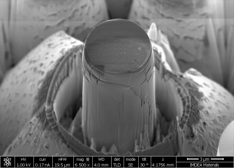
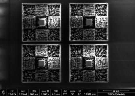
16 Pillar carved on the AS4/8852 resin pockets

17 Micropillar compression

18 Micropillar compression Load-displacement curve Stress-strain curve Substrate and pillar are made of the same material! Influence of pillar geometry!

19 Strain concentration due to taper angle
20 Micropillar geometry dh dp H D D H H D D D H E ) tan 2 ( 4 8 ) (1 1,, Substrate = polymer D0 H ρ β [3] Y. Yang, J.C. Ye, J. Lu, F.X. Liu, P.K. Liaw, Effects of specimen geometry and base material on the mechanical behavior of focused-ion-beam-fabricated metallic-glass micropillars, Acta Mater. 57 (2009)
21 Micropillar compression A 0 σ yc =210 MPa L 0 E = 3.5 GPa < 5.07 GPa
22 Test comparison Test method σyc (MPa) E (GPa) Nanoindentation??? 5.07 Micropillar compression Young modulus provided by the supplier, E = 4.67 GPa (tensile test ASTM D 638)
23

24 A Stiff skin due to FIB attack

25 Stiff skin due to FIB attack (detail A)
26 Micropillar stiff skin Composite material under isostrain condition E core E 4E skin 1 t D skin 0 2t D skin 0 t D 2 skin 0 2 t skin E skin 19nm 30GPa [4] S. Wang, Y. Yang, L.M. Zhou, Y.-W. Mai, Size effect in microcompression of epoxy micropillars, J. Mater. Sci. 47 (2012)
27 Test comparison Applying both corrections for skin and pillar geometry Test method σyc (MPa) E (GPa) Nanoindentation??? 5.07 Micropillar compression 210??? Young modulus provided by the supplier, E = 4.67 GPa (tensile test ASTM D 638) Now, the Young modulus derived from micropillar compression is closer to the one found by means of instrumented nanoindentation

28 Pillar size effect
29 Pillar size effect V f,skin 0 σ max 165 MPa
30 Combined methodology Applying both corrections for skin size and pillar geometry... Test method σyc (MPa) E (GPa) Nanoindentation??? 5.07 Micropillar compression E (GPa) σyc (MPa) β( ) Mater curves β corresponding to σ yc obtained from the micropillar compression tests
31 Conclusions & future Conclusions Polymer matrix elasto-plastic behavior has been determined, according to a Drucker-Prager constitutive model, combining different micromechanical experimental techniques : instrumented nanoindentation and micropillar compression tests Major advantages and drawbacks of both experimental techniques when applied to polymer characterization have been pointed out Micropillar compression stands out a promising technique that can applied for polymers characterization. It has potential for in-situ application (as instrumented nanoindentation) while provides an direct measurement of the stress-strain curve (as macro compression test) Future work Study the influence of the strain rate and temperature on the micropillar response Study the visco-elastic properties of the polymer by means of micropillar creep tests Explore the influence of new pillar geometries in the mechanical properties


32 Thank you for your attention
33 Instrumented indentation Advantages In-situ technique (it can take into account residual thermal stresses, manufacturing and environmental conditions) Sample preparation and test simplicity Well-known technique already used at IMDEA Disadvantages Interpretation can be complicated (it depends on the material type) It requires additional tests to estimate E, σ yc and β Tends to overestimate material stiffness due to fiber constraint effect Finding resin pocket on the composite cross-section is not straightforward Non-conventional equipment is required
34 Micropillar compression Advantages Stress strain curves are easy to obtain In-situ technique potential (micropillars can be carved anywhere on the composite cross-section) High resolution offering the possibility of real time monitoring of the deformation Disadvantages Non-conventional equipment is required Stress-strain curves depend on pillar geometry (dimensions have to be determined accurately) FIB induced damage affects the measurements


35
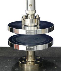

36 Macroscopic compression Load H L W
37 σ (MPa) σ (MPa) Macroscopic compression Load Load 10 mm 6 mm 3 mm 5 mm 5 mm 3 mm Machine compliance included σyc=160 MPa σyc=164 MPa E = 3.4 GPa E = 3.12 GPa ε ε