Analysis of micro-structuring polymer replication by micro-injection moulding and hot embossing
|
|
|
- Alan McCoy
- 5 years ago
- Views:
Transcription

1 4M2007 Conference on Multi-Material Micro Manufacture 3-5 October 2007 Borovets Bulgaria Analysis of micro-structuring polymer replication by micro-injection moulding and hot embossing M. Sahli, C. Millot, C. Roques-Carmes, C. Khan Malek, J.C. Gelin & T. Barriere FEMTO-ST Institute/Dpt. LPMO, CNRS UMR 6174,, Besançon cedex, France. 1/17
2 OUTLINE ❶ INTRODUCTION ❷ EXPERIMENTAL PROCEDURE ❸ EXPERIMENTAL RESULTS ❹ CONCLUSIONS & FUTURE PROSPECTS 2/17

3 INTRODUCTION Hot embossing exploits the heating of a polymer just above its glass transition temperature to imprint microstructures on a polymer substrate using a master mould. In contrast to hot embossing, micro-injection molding requires that the polymer should be melted before the injection stage. Objective: Compare both processes in term of quality of microparts 3/17
4 EXPERIMENTAL PROCEDURE The same mould was used for both techniques, hot embossing & injection moulding 2 shapes of micro-features were selected to study the filling factor of the microcavity Polymer used for the experiments: Polypropylene (PP) Measurement of replicas conducted using scanning mechanical microscopy (3D cartographies) Material Density Glass transition temperature T g ( C) Specific heat C p (J/kgK) Thermal conductivity ג (W/mK ) Melting temperature ( C) Polypropylene (PP, EP548N) Typical properties of PP 4/17
5 EXPERIMENTAL PROCEDURE Injection Molding Machine Hot Embossing Machine Battenfeld Microsystem 50, bi-injection 5/17
6 EXPERIMENTAL PROCEDURE Processing parameters for hot embossing & micro-injection moulding Embossing temperature Injection temperature Moulding die temperature Moulding pressure Injection Velocity Holding time Hot embossing C bar s Micro-injection moulding C 40 C 10 MPa 20 mm 3 /s 10s Substrate 1 mm thick PP plate PP pellets 6/17
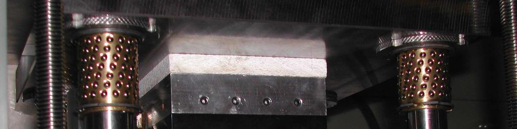
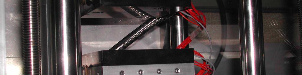
 Guiding blocks 3D mould for micro-injection moulding Insulator Fixing plates Ejector pins Ejector in ejection position (after injection) Floating")
7 EXPERIMENTAL PROCEDURE The micro-structured die realized on the surface of the ejector tips The micro-cavity composed by the microstructured ejector & the floating insert Ejectors Microcavity Ejector in injection position (before and during injection) Guiding blocks 3D mould for micro-injection moulding Insulator Fixing plates Ejector pins Ejector in ejection position (after injection) Floating insert 7/17
 for the pyramidal shape Microstructured dies 100µm 100µm 1 2 Ejector Circular grooves Micro pyramids Radius: 300-700 µm 450 µm")
8 EXPERIMENTAL PROCEDURE The dies were manufactured either by : 1. KERN high speed micromachining for the circular grooves 2. or by indentation (Vickers indenter) for the pyramidal shape Microstructured dies 100µm 100µm 1 2 Ejector Circular grooves Micro pyramids Radius: µm 450 µm wide base 100 µm depth 80 µm depth 8/17


9 EXPERIMENTAL RESULTS: hot embossing and injection moulding Replicas made by both techniques are similar in shape and size to the dies The topographical state of the replica surfaces is similar to the masters Micro pyramidal shape die 100µm Microinjection moulding Micro circular groove shape die 100µm 100µm 100µm Master 100µm Hotembossing 100µm Master Replica Replica 9/17

10 EXPERIMENTAL RESULTS: hot embossing Effect of polymer temperature on the hot embossing process The hot embossing can be carried out at a temperature just above T g but the reproduction quality is not optimized. Replica C Die C 120 C 130 C 140 C 40 T g (PP) = 90 C 100µm h e ig h t [µ m ] Width [µm] The higher the temperature of the heating step, the higher the filling rate and the more conformal the replica => This observation is related to the fluidity variation of the polymer since the viscosity varies according to the temperature. 10/17

11 EXPERIMENTAL RESULTS: hot embossing Effect of polymer temperature on the hot embossing process The reproduction quality in term of aspect depends on the selected temperature. The micro-pyramidal shape cavity is completely filled at temperatures higher than T g +40 C. Die C 14/19 11/17
12 EXPERIMENTAL RESULTS: hot embossing and injection moulding Influence of process on the quality of the microparts The filling ratio is over 80% using both replication techniques. The filling rate can be improved by modifying the processing parameters. Cavity Microinjection moulding Hot embossing Volume (10 6 µm 3 ) Filling rate (%) Width (µm) Depth (µm) /17
 Injection-moulded replica Hot-embossed replica (140 C)")
13 EXPERIMENTAL RESULTS: hot embossing and injection moulding Influence of process on the quality of the microparts 3D shape comparison of master and replicas shows sharper features in injection-moulded replica than in hot-embossed replica Master (after numerical inversion) Injection-moulded replica Hot-embossed replica (140 C) 13/17

14 EXPERIMENTAL RESULTS: hot embossing and injection moulding Influence of process on the quality of the microparts Zones of plastic deformation generated by the contact of indentor at the edges of prints are reproduced whatever the selected temperature. Micro-pyramidal shape die Replicas Depth [µm] Cavity Hot embossing Injection Width [µm] micro injection moulding hot embossing (140 C) 14/17
15 EXPERIMENTAL RESULTS: hot embossing and injection moulding Influence of process on the quality of the microparts Both the polymer parts obtained by hot embossing and micro-injection moulding are in conformity with the mould in the case of circular grooves. Hot embossing (140 C) h e ig h t [µ m ] Hot embossing Microinjection Micro injection moulding Width [µm] Under the same experimental conditions, the filling of circular grooved shapes is easier than that of the micro pyramidal shapes. 15/17
16 CONCLUSION Two replication techniques, hot embossing and micro-injection moulding, were compared in term of: dimensions of replicated parts, quality of reproduction of the imprint surface, & filling ratio of cavities. The dimensions of replicas in PP were measured using SMM. The shapes of the imprints were reproduced with a correct accuracy. The same quality of reproduction can be obtained using the hot embossing process at low temperature (T g + 30 C) as using injection moulding at much higher temperature (240 C). For hot embossing at T g + 30 C, the filling of the circular cavity is better than that of the micro-pyramidal shape cavity. This has been modeled using an analytical model. 16/17
 - For a finer description of the process, the thermal behaviour of the polymer needs to be taken into account.")
17 PERSPECTIVE Modeling of the hot embossing process by the finite elements method: - First, in 2D simulation (circular imprint case ); - Second, 3D simulation (micro-pyramidal shape case) - For a finer description of the process, the thermal behaviour of the polymer needs to be taken into account. 17/17
18 Thank you very much for your attention! FEMTO-ST Institute/Dpt. LPMO, CNRS UMR 6174,, Besançon cedex, France.
19


 Floating insert")
20 EXPERIMENTAL PROCEDURE Micro-manufacturing steps for micro-parts moulding by hotembossing Microcavity Upper plate Ejector Polymer disk Polymer disk Micro-parts Lower plate Heating + contact (before compression) Floating insert Compression + demoulding (1) Ejectors Demoulding (2) 9/19
21 Introduction The reduction of the size and the weight of micro-components remains a major technological constraint. In this context, various technologies such as hot embossing, micro-injection moulding and micro-precision casting are technologies for the manufacturing of such components. The same interchangeable micro-mould was used for both the hot embossing and the injection moulding processes 3/19
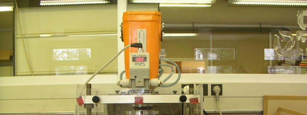

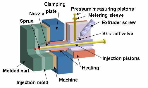
22 Experimental procedure Injection Molding Machine Hot Embossing Machine 8/19
23 Materials & Methods Typical properties of the polymer used in the experiments are collected in this Table Material density glass transition temperature T g ( C) specific heat C p (J/kgK) thermal conductivity ג (W/mK ) melting temperature ( C) Polypropylene (PP, EP548N) /19
24 Materials & Methods Typical properties of polymer Material PP polymer processing parameters for micro-injection moulding & hot embossing Material density glass transition temperature T g ( C) specific heat C p (J/kgK) thermal conductivity ג (W/mK ) melting temperature ( C) Polypropyle ne (PP, EP548N) Embossing temperatur e Injection temperatur e Moulding die temperatur e Embossing pressure Injection Velocity Hot embossing 120 C - - 4bar - Micro-injection moulding C 40 C - 20mm 3 /s Holding time [30-60]s 10s 5/19

25 1. Floating insert Materials & Methods 3D Moulds conception for micro-injection moulding 2. Guiding blocks 3. Ejectors pins 4. Die cavities Ejectors 6. Insulator 7. Fixing plates /19
26 Materials & Methods The micro-structured die cavities were realized on the surfaces of ejectors The cavities were manufactured either by : 1. KERN high speed micromachining center for the circular grooves, 2. or by indentation (Vickers indenter) for the pyramidal shape. Micro die cavity 100µm 100µm 1 2 Circular grooves Micro pyramids 7/19
27 Experimental procedure Micro-manufacturing steps for micro-parts moulding Polymer disk Upper plate Ejector Polymer disk components Lower plate Floating insert Ejectors 9/19
28 Experimental procedure Micro-manufacturing steps for micro-parts moulding Polymer disk Upper plate Ejector Polymer disk components Lower plate Floating insert Ejectors 9/19
29 100µm 100µm 2. Micro pyramidal shapes Experimental results Replicas of the pyramids are similar in shape and size with those of the mould and present also surface qualities. Micro pyramidal shapes die cavities a 100µm 100µm 100µm 100µm 100µm 100µm Replica realized by micro-injection moulding Replica realized by hot embossing 13/19