High Temperature Secondary Hydriding Experiments with E110 and E110G Claddings
|
|
|
- Sabrina Lamb
- 5 years ago
- Views:
Transcription


1 High Temperature Secondary Hydriding Experiments with E110 and E110G Claddings Zoltán Hózer, Imre Nagy, András Vimi, Mihály Kunstár, Péter Szabó, Tamás Novotny, Erzsébet Perez-Feró, Zoltán Kis, László Szentmiklósi, Márta Horváth, Anna Pintér Csordás, Eszter Barsy, Katalin Kulacsy, Centre for Energy Research, Hungarian Academy of Sciences (MTA EK) Mirco Grosse Karlsruhe Institute of Technology (KIT) 18 th International Symposium on Zirconium in the Nuclear Industry May 15-19, 2016, Hilton Head, SC, USA
2 Introduction 2
3 Secondary hydriding High temperature accident conditions Ballooning and burst of cladding Steam access to inside fuel rod Oxidation of internal cladding surface Accumulation of H inside fuel rod H uptake by metallic Zr Very brittle zones 3
4 Secondary hydriding experiments JAERI ANL Studsvik QUENCH MTA EK Single rod tests Bundle tests + Non-irradiated materials Irradiated materials + + Ring compression tests + Four point bending tests Axial tensile tests + Zircaloy Zircaloy ZIRLO TM + Opt. ZIRLO TM + M5 + E110 + E110G + H.Uetsuka, T. Furuta S. Kawasaki, Journal of Nuclear Science and Technology, 18[9], pp (September 1981). 4
5 Secondary hydriding experiments JAERI ANL Studsvik QUENCH MTA EK Single rod tests Bundle tests + Non-irradiated materials Irradiated materials + + Ring compression tests + Four point bending tests Axial tensile tests + Zircaloy Zircaloy ZIRLO TM + Opt. ZIRLO TM + M5 + E110 + E110G + 5
6 Secondary hydriding experiments JAERI ANL Studsvik QUENCH MTA EK Single rod tests Bundle tests + Non-irradiated materials Irradiated materials + + Ring compression tests + Four point bending tests Axial tensile tests + Zircaloy Zircaloy ZIRLO TM + Opt. ZIRLO TM + M5 + E110 + E110G + 6
7 Secondary hydriding experiments JAERI ANL Studsvik QUENCH MTA EK Single rod tests Bundle tests + Non-irradiated materials Irradiated materials + + Ring compression tests + Four point bending tests Axial tensile tests + Zircaloy Zircaloy ZIRLO TM + Opt. ZIRLO TM + M5 + E110 + E110G + 7
8 E110 and E110G Russian Zr alloys with 1%Nb E110 electrolytic E110G sponge technology Similar compositions Element E110 E110G Element E110 E110G Mg 0.5 ppm 1.5 ppm Fe 45 ppm 500 ppm Al 0.5 ppm 10 ppm Ni 15 ppm 15 ppm Si 1 ppm 35 ppm Cu 0.5 ppm 5 ppm Cr 10 ppm 30 ppm Hf 100 ppm 10 ppm Mn 0.1 ppm 5 ppm Halogen content E110 E110G F 30 ppm 10 ppm Cl 3 ppm 1 ppm 8


9 E110G Oxidation in steam E s 900 C Z. Hózer, E. Perez-Feró, T. Novotny, I. Nagy, M. Horváth, A. Pintér-Csordás, A. Vimi, M. Kunstár, T Kemény,, STP 1543 (2015) pp
10 ECR (%) Oxidation in steam C E Cathcart-Pawel E110G Oxidation time (s) Z. Hózer, E. Perez-Feró, T. Novotny, I. Nagy, M. Horváth, A. Pintér-Csordás, A. Vimi, M. Kunstár, T Kemény,, STP 1543 (2015) pp
11 Experimental details 11
 10 Tube")
12 Experimental facility 1 High purity argon gas 2 Steam generator 3 Precision pump 4 Water tank 5 High purity argon gas 6 Stepper-controlled proportional valve 7 Control unit for stepper motor 8 Puffer tank 9 Thermal Conductivity Detector (TCD) 10 Tube furnace 12

13 Cladding sample 250 mm long tubes E110 and E110G alloys Al 2 O 3 pellets inside Connection to pressurization system Plugged other end 13
14 Test procedure 14
15 Test matrix Sample Alloy Burst temperature ( C) Pressurization rate (bar/s) Oxidation temperature ( C) Oxidation time (s) Cool-down E110ref E Slow ESH1 E Slow ESH2 E Slow ESH3 E Slow E110Gref E110G Slow GSH12 E110G Slow GSH22 E110G Slow GSH3 E110G Slow GSH42 E110G Slow GSH52 E110G Slow GSH62 E110G Fast 15
16 Halden IFA Sample Alloy Burst temperature ( C) Test matrix Pressurization rate (bar/s) Oxidation temperature ( C) Oxidation time (s) Cool-down E110ref E Slow ESH1 E Slow ESH2 E Slow ESH3 E Slow E110Gref E110G Slow GSH12 E110G Slow GSH22 E110G Slow GSH3 E110G Slow GSH42 E110G Slow GSH52 E110G Slow GSH62 E110G Fast ANL OCL#11 16


17 Four point bending Characterization of load bearing capabilities INSTRON tensile test machine 17


18 Post-test examinations Metallography SEM Prompt gamma activation imaging Hot extraction Neutron radiography 18
19 Results 19
 Oxidation")

20 E110 tests Sample View after burst and oxidation Burst pressure (bar) Oxidation temperature ( C) and time (s) E110ref ESH ESH ESH
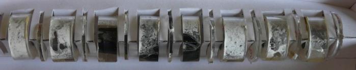
21 E110G tests Sample View after burst and oxidation Burst pressur e (bar) Oxidation temperature ( C) and time (s) E110Gref GSH GSH GSH GSH GSH GSH
 H axial distribution 1000 PGAI Neutron radiography 800 600 400 200 0-100 -50")
22 H content wt. (ppm) H axial distribution 1000 PGAI Neutron radiography Distance from burst center (mm) E110G GSH C 200 s 22
23 H content wt. (ppm) H axial distribution 2000 PGAI hot extraction E110 ESH C 200 s Distance form burst center (mm) 23

24 Load (N) E110/E110G four point bending ESH1 600 GSH Displacement (mm) 24
25 Load (N) E110G four point bending non-oxidised sample oxidation at 1000 C for 1200 s oxidation at 1000 C for 200 s oxidation at 1000 C for 3600 s Displacement (mm) 25


26 E110/E110G oxidation E110 (ESH3) 1000 C for 3600 s E110G (GSH3) 26
27 Conclusions 27
28 The ballooned section after oxidation similarly to other Zr alloys becomes the weakest segment of the fuel with E110 or E110G cladding, too. Even short oxidation times (e.g. 200 s at 1000 C) resulted in brittle behavior of both E110 and E110G zirconium alloy samples. E110 tubes lost their load bearing capability or even integrity much earlier than the E110G samples treated under similar conditions. 28
29 The axial distribution of absorbed hydrogen in the cladding was similar to the observation of tests with other Zr alloys (Zircaloy-4, ZIRLO TM ). The peak of hydrogen content was found not in the middle of burst, but for some centimeters further. The experimental data have been collected into a database and are available for model development and validation purposes. 29

30 Köszönöm a figyelmet! Thank you for your attention. 30