WHAT MAKES A GOOD FE PACKING FOR NEW/USED VALVES?
|
|
|
- Nelson Pitts
- 5 years ago
- Views:
Transcription


1 WHAT MAKES A GOOD FE PACKING FOR NEW/USED VALVES? Carlos D. Girão P.E., M.Sc. Teadit Packing & Gasket Pvt. Ltd.
2 BACKGROUND 20YEARS AGO Lack of Clear Directions! Consult packing manufacturer and/or plant engineering department for guidance on torque (FSA) Tighten the gland bolts to the point where heavy resistance to wrenching is felt X% of Compression FE Emission Labs being Set up


3 FUTURE USA announced in 2015 ambitious new goal to cut methane emissions from the oil and gas sector by 40 to 45 percent below 2012 levels by first- hyperspectral- video- camera- detects- explosive- gas- leaks/ (Match 4 th 2015)
 Certified Low- Leaking Valve Packing Technology shall mean valve packing technology for which a manufacturer has issued: (i) a written guarantee that the valve packing technology will not leak")
4 TODAY - LOW-E VALVE TECHNOLOGY R&D + INTRO Low- E Valve is defined as: ( Certified Low- Leaking Valve Packing Technology shall mean valve packing technology for which a manufacturer has issued: (i) a written guarantee that the valve packing technology will not leak above 100 ppm for five (5) years; (ii) a written guarantee, certification or equivalent documentation that the valve packing technology has been tested pursuant to generally- accepted good engineering practices and has been found to be leaking at no greater than 100 ppm CONSENT DECREE requires the implementation and defines the directives ENHANCED LDAR program prescribes the use of LOW-E TECHNOLOGY Certified Low- E Valves w/ Low Emissions Sealing System

 ü Otimization")

5 PACKING R&D ü Installation with Controlled Torque (ASME PVP Paper ) ü Optimum Number of rings (ASME - PVP ) ü Otimization of Corrosion Inhibitors (VW2010) ü Limitation on the Maximum use of PTFE (ASME PVP )


6 MINIMUM SEATING STRESS Packing: Style A: Flexible Graphite Yarn reinforced with an Inconel wire mesh. Style D: Expanded PTFE filled with Barium Sulphate.
7 MINIMUM SEATING STRESS Ni-Cr Wire Mesh Reinforced Yarn Flexible Graphite Packing (no impregnation) Expanded PTFE filled with Barium Sulphate Packing 1,00E+00 1,00E+00 Leak Rate (mbar l/s) 1,00E-01 1,00E-02 1,00E-03 1,00E-04 Leak Rate (mbar l/s) 1,00E-01 1,00E-02 1,00E-03 1,00E-04 1,00E-05 1,00E-05 1,00E ,00E Stress (MPa) Stress (MPa) Packing Style MPa S min(0.01) psi A D


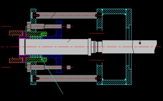

8 PACKING DRAG AND FORCE TRANSMISSION
 0 20 40 60 80 100 Gland Stress (MPa) x (%) 60% 40% 20% 0% 2 Rings 4 Rings 5 Rings 7 Rings Smin(0,01) 0 20 40 60 80 100 Gland Stress (MPa) Results")
9 PACKING DRAG AND FORCE TRANSMISSION 100% 80% Ni-Cr Wire Mesh Reinforced Yarn Flexible Graphite Packing (no impregnation) 100% 80% Expanded PTFE filled with Barium Sulphate Packing x (%) 60% 40% 20% 0% 2 Rings 4 Rings 5 Rings 7 Rings Smin(0,01) Gland Stress (MPa) x (%) 60% 40% 20% 0% 2 Rings 4 Rings 5 Rings 7 Rings Smin(0,01) Gland Stress (MPa) Results incompatible with the traditionally used Radial Stress Distribution graph for stresses above the MSS
10 PACKING DRAG AND FORCE TRANSMISSION Friction Force (N) Ni-Cr Wire Mesh Reinforced Yarn Flexible Graphite Packing (no impregnation) 2 Rings 4 Rings 5 Rings 7 Rings Friction Force (N) Expanded PTFE filled with Barium Sulphate Packing 2 Rings 4 Rings 5 Rings 7 Rings Gland Stress (MPa) Gland Stress (MPa) Friction force difference between Graphite and PTFE packings
11 COATING STEM TORQUE Test at Cycling Conditions [API 622] 77 Mpa C - 40bar (Methane) /09 STYLE: 6% 9 Disp.PTFE 60% 2235/05 STYLE: 28% 5 Disp.PTFE 60% 2235/12 STYLE: 8% 12Disp.PTFE 45% 2235/10 STYLE: 3% 10Disp.PTFE 30% 70 Torque (N.m) N Cycle STYLE 10 and 12 = High Torque STYLE 5 and 9 = Torque OK!
12 THERMAL EXPANSION 5,00 4,50 4,00 3,50 D s 1 (MPa) 3,00 2,50 2,00 1,50 1,00 0,50 0,00 Style A Style B Style C Style D Style Yarn Filler Comparative e-ptfe content A e-ptfe None 100% e-ptfe B C e-ptfe e-ptfe Barium Sulphate Barium Sulphate D e-ptfe Graphite B% < A% C % < A% & B% D% < A%, B% & C%
 Steel 1 Barium Sulphate 1")

13 THERMAL EXPANSION Material (10-5 K - 1 ) Steel 1 Barium Sulphate 1 Graphite 1 PTFE 12 PTFE Packing Extrusion due to Thermal Expansion


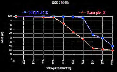


14 THERMAL RESISTANCE

15 GALVANIC CELL - CORROSION


16 CORROSION INHIBITOR 3,00% 2,50% 2,00% 1,50% 1,00% 0,50% 0,00% Average Mass Loss Inhibitor 1 Inhibitor 2 Inhibitor 3 no Inhibitor Inhibitor 4 Inhibitor 1 Inhibitor 2 Inhibitor 3 no Inhibitor Inhibitor 4 Inhibitor 1 Inhibitor 2 Inhibitor 3 no Inhibitor Inhibitor


17 CORROSION INHIBITOR Packing Sample P: with Zinc Powder. Packing Sample W: with Zinc Wires in the core.
18 DENSITY CONTROL Density Control Specially on Molded Rings Over Compressed rings will NOT be able to fill the voids


19 FUGITIVE EMISSION TEST RIGS


20 R&D Results
21 WHAT MAKES A GOOD FE PACKING FOR NEW/USED VALVES? Controlled Packing Density Reduced Stem Drag - the least PTFE possible Thermal Resistant and Fire Safe Corrosion Inhibition Designed Assembly Stress
22 SUCCESS FACTORS - TESTING API 624 Key Success Factors Valve and packing manufacturer relationship Quality product and good communication yields good results Eyebolt nut / Gland flange torque values Machining tolerances (stem, stuffing box, gland, etc.) Lubrication Third- party tester that is competent Integrity of test stand (Revolution speed, Safety, etc..)


23 INSTALLER TRAINING: 3 KEY ELEMENTS 1 PRODUCT 2 TORQUE 3 INSTALLATION

")

24 INSTALLATION Stuffing Box and Stem finish as per STD Tolerances as per best practice as per STD Rings with Cuts 90º apart 5 Rings = Desirable Proper torque (k factor influence) 100 Bolt Design Stress (%) New Hardend G8 Washers No Washers Carbon Steel Common Washers
25 API 624 RESULTS
 The financial impact of unscheduled plant shutdown due to Valve Packing Blow out was $50,000,000.")
26 FIELD Field MONITORING Tests RESULTS 4Years Since the introduction of LE packing at our TCO Tengiz facility in Kazakhstan four years ago, we have experienced zero leaks on every reconditioned valve we have repacked with (Bill Ross) The financial impact of unscheduled plant shutdown due to Valve Packing Blow out was $50,000,000. Good Practice: recommend retightening once after initially being put into service.
27 SEALING FOR A SAFER AND GREENER TOMORROW What makes a good FE packing for new/used valves? Carlos D. Girão cdgirao@teadit.in Teadit Packing & Gasket Vadodara, India Thank you!