MOLTEN SALT ACTINIDE RECYCLER & TRANSFORMING SYSTEM WITH AND WITHOUT TH-U SUPPORT: MOSART
|
|
|
- Lee Goodman
- 5 years ago
- Views:
Transcription


1 MOLTEN SALT ACTINIDE RECYCLER & TRANSFORMING SYSTEM WITH AND WITHOUT TH-U SUPPORT: MOSART Dr. Victor Ignatiev NRC Kurchatov Institute, Moscow, Russia 7 June 2018

2 Meet the presenter Dr. John E. Kelly is the Deputy Assistant Secretary for Nuclear Reactor Technologies in the U.S. Department of Energy s Office of Nuclear Energy. His office is responsible for the civilian nuclear reactor research and development portfolio, which includes programs on Small Modular Reactors, Light Water Reactor Sustainability, and Advanced (Generation IV) Reactors. His office also is responsible for the design, development, and production of radioisotope power systems, principally for missions of the U.S. National Aeronautics and Space Administration. In the international arena, Dr. Kelly is the immediate past chair of the Generation IV International Forum (GIF) and the former chair of the International Atomic Energy Agency s Standing Advisory Group on Nuclear Energy. Prior to joining the Department of Energy in 2010, Dr. Kelly spent 30 years at Sandia National Laboratories, where he was engaged in a broad spectrum of research programs in nuclear reactor safety, advanced nuclear energy technology, and national security. In the reactor safety field, he led efforts to establish the scientific basis for assessing the risks of nuclear power plant operation and specifically those risks associated with potential severe accident scenarios. His research focused on core melt progression phenomena and this led to an improved understanding of the Three Mile Island accident and, more recently, the Fukushima Daiichi accident. In the advanced nuclear energy technology field, he led efforts to develop advanced concepts for space nuclear power, Generation IV reactors, and proliferation-resistant and safe fuel cycles. These research activities explored new technologies aimed at improving the safety and affordability of nuclear power. Dr. Victor Ignatiev works at the NRC- Kurchatov Institute, Moscow, Russia both as the Head of the Molten Salt Reactor Laboratory (since 2012) and as a Professor (since 2009). He graduated from the Nuclear Power Systems Moscow Physical Engineering Institute, USSR, in 1976, and earned his Ph.D. in 1986 from the Kurchatov Institute of Atomic Energy, Moscow, USSR. His Ph.D. research focused on molten salt reactors. Since 2014, he has been the co-chair of Generation IV International Forum MSR pssc. In 1985, he received the Kurchatov Award on the Fundamental Studies of Molten Salt Reactors and in 2016, he received the Kurchatov Award on Engineering studies of Molten Salt Reactors. The main area of his research activities focus on Molten Salt Reactor: (1) Th - U fuel cycle and TRU burners, (2) Combined materials compatibility & salt chemistry control in selected molten salt environments Dr. Kelly received at parameters his B.S. degree simulating in nuclear engineering designs operation, from the University (3) Physical of Michigan & chemical in 1976 properties and his Ph.D. for in fuel nuclear engineering from the Massachusetts Institute of Technology in and coolant salt compositions, and (4) Flow sheet optimization, including reactor physics, thermal hydraulics and safety related issues. Ignatev_VV@nrcki.ru 2
3 Contents Introduction Core neutronics, thermal hydraulics and fuel cycle properties Safety aspects Key physical and chemical properties of fuel salt Materials compatibility and salt chemistry control Summary 3

4 In MSR devices solid fuel elements are replaced by liquids Mechanical engineering device presumes that the fuel (solid) has to be used in a max condensed form that excludes reprocessing and has advantage of technical simplicity while reactor operating. Chemical engineering device has not only possibilities of general benefits such as unlimited burn-up, easy and relatively low cost of purifying and reconstituting the fuel (fluid), but also there are some more specific potential gains. 4
5 This contribution proves the feasibility of Molten Salt Actinide Recycler & Transformer (MOSART) system fueled with TRU trifluorides from SNF in different scenarios without and with U-Th support The webinar has the main objective of presenting the fuel cycle flexibility and inherent safety features of the MOSART system while accounting technical constrains and experimental data received in our studies. MOSART design options with homogeneous core and fuel salt with high enough solubility for transuranic elements trifluorides were examined. A brief description is given of the experimental results on key physical and chemical properties of fuel salt as well as combined materials compatibility to satisfy MOSART system requirements. 5


6 Started with TRU Fluorides from LWR SNF MOSART can operate in different modes: Transmuter, Self-sustainable, Breeder Used fuel Reprocessing Waste conditioning VVER ILW ILW disposal Fresh fuel U, Pu TRU Enrichment & fabrication MSR Uranium Production 6

7 MOSART Transforming Reactor System HN80MTY Circuits, Vessel, Heat exchangers 600 / 720 C Creep, Creepfatigue, Thermal fatigue, Aging, Welds HN80MTY Intermediate circuit / 620 C Aging, Welds, Compatibility NaF-NaBF 4, Oxidation, Wastage System burner / breeder Fluid streams 1 2 Power capacity, MWt Fuel salt inlet/outlet temperature, o C Fuel salt composition, mole % Blanket salt composition, mole % Max temperature of the fuel salt in the primary circuit made of special Ni- alloy is mainly limited by Te IGC depending on salt Redox potential Min temperature of fuel salt is determining not only its melting point, but also the solubility for AnF 3 in the solvent for this temperature 600 / /720 72LiF 27BeF 2 1TRUF 3 no 75LiF 16.5BeF 2 6ThF 4 2.5TRUF 3 75LiF 5BeF 2 20ThF 4 7


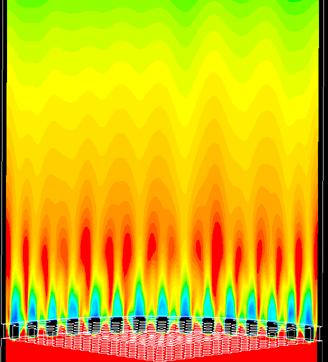


8 MOSART Transforming Reactor System Heat source, W/m 3 Velocity, m/s r = 1,65 m T max wall: 947 K; T max fluid : 1192 K 8
9 MOSART Fuel Cycles Solvent, mole % Feed MA/TRU Loading (EOL), t TRU/MA, kg/yr 15LiF-58NaF-27BeF /73 73LiF-27BeF /73 73LiF-27BeF /260 73LiF-27BeF /330 Contribution to Keff Isotope BOL EOL Pu 239 0,75 0,25 Pu Concentration, mole % TRU Molar Concentration MOSART with LiNaBe/F solvent MOSART with LiBe/F solvent Time (year) Pu 241 0,25 0,41 Cm 245-0,28 9

10 In MOSART core, the limitations on the radiation resistance of structural materials, along with the possibilities of heat removal, represent the main factors that inhibit the increase in the core specific power > 140 W / cm 3 The temperature in the fuel circuit due to the decay heat without heat sink should not reach the maximum temperature for the structural material Нe embrittlement for Ni-base alloy at T > 500 С 58 Ni + n 55 Fe + 4 He, ( >1MeV); 60 Ni + n 57 Fe + 4 He; 10 B + n 7 Li + 4 He. 58 Ni + n 59 Ni + γ, 59 Ni + n 56 Fe + 4 He. Basing on neutron fluence (3,8*10 21 n/(cm 2 yr)) and temperature ( K) reflector should be changed in 5 yrs 10


11 MSR Engineered Safety Features Fuel Processing Unit Fuel Circuit Intermediate Circuit Power Conversion System Nuclear fuel is a fluid. It circulates throughout the RCS, transfers heat to heat exchanger and becomes critical only in core Possible initiators of RCS breach accident: pipe failure missiles, and pressure or temperature transients in RCS, failure of the boundary between the 1st and 2nd salts in heat exchanger Problem of developing RCS which will be reliable, maintainable, inspectable over the plant's lifetime will probably be key factor in demonstrating ultimate safety and licenseability MSR must be designed so that decay heated fuel salt reaches the drain tank under any credible accident conditions 11
12 MOSART Transients Analysis Temperature [C] Temperature [C] Fuel_av Salt_out 850 Salt_in 800 Graph_av ULOF Time [sec] Over-Cooling Fuel_av Salt_out Salt_in Graph_av Time [sec] Temperature [C] Temperature [C] ULOH Fuel_av Salt_out Salt_in Graph_av Time [sec] UTOP + 500pcm Fuel_av Salt_out Salt_in Graph_av Time [sec] The MOSART is expected not to be seriously challenged by the major, unprotected transients such as ULOF, ULOH, overcooling, or even UTOP. The system was shown to buffer reactivity insertion of up to + 1.5$. System temperatures are expected to rise only ~300C above nominal under this severe transient conditions. The mechanical and structural integrity of the system is not expected to be impaired. 12
13 Severe Accident with the Rupture of the Main Fuel Salt Pipe and Fuel Discharged on the Reactor Cell Bottom The model based on mass transfer theory describing main radionuclides distribution between the fuel salt, metallic surfaces of the primary Isotope A s /A o A g /A s A g /A o circuit, graphite and the gas purging system was applied for calculation Te129 0,25 1 0,25 releases to the containment atmosphere. Te132 0, ,005 As a criteria characterizing an isotope yield from the fuel salt is accepted Ru103 0,01 1 0,01 the ratio of this isotope activity changed into a gas phase of a Ru106 0, ,001 containment (A g ) to its full activity built up in a reactor by the moment Nb95 0, ,034 of the accident (A 0 ) Zr95 0,99 0,0011 0,0011 After accident considered all noble gases and metals available should Sr89 0,99 0, ,00046 move to the gas phase (A g /A s =1, where A g /A s -the ratio of isotope Sr90 0,98 0, ,00046 activity in the gas phase of the containment after an accident to its La140 0,98 0,026 0,025 activity concentrated in the fuel salt by the moment of the accident). Ce141 0,99 0,0024 0,023 However, already as it noted before during the normal operation these Ce144 0,96 0,0024 0,023 nuclides are almost completely leave the fuel salt. I131 0,62 0,43 0,27 For MSR the total release of radioactivity would be significantly lower I133 0,94 0,43 0,43 (by I - 2 orders of magnitude compared to LWR), though for several Cs137 0,7 0,016 0,011 particular nuclides such I 131 and I 133 the differences are smaller 13
14 Frequency Distribution for the Probability of Accidents in the MSR Accidental Frequency LWR MSR Probability of an accident with a relatively low impact for MSR is higher than for LWR. This is due to the possibility of leakage of radioactive liquid fuel in case of accidents in the pump, piping, valves. The consequences of severe accidents in particular, leading to the release of radioactive products into the environment for MSR significantly less than for LWRs. Consequences of Accidents Taube M., Fast and thermal molten salt reactors with improved inherent safety // TANS, 1981, Summer meeting, pp

15 Gen IV MSR container materials Combined environments Corrosion effects Radiation Fast neutrons Fuel addition Fission products Metallic alloy Impurities High Temp Creep, Creepfatigue, Thermal fatigue, Aging, Welds Corrosion Redox, Heat up, Velocity Molten salt Gas Graphite 15

16 In temperature range С about 70 differently alloyed specimens of HN80MT were tested. Among alloying elements there were W, Nb, Re, V, Al and Cu Element Hasteloy N US Hasteloy NM US HN80М-VI Russia HN80МTY Russia MONICR Czech Rep Experiments results in polythermal loops with redox potential measurement demonstrated that operations with Li,Be/F salt, fuelled by UF 4 or PuF 3, are feasible using carefully purified molten salts and loop internals. Corrosion rate of HN80М-VI and HN80МTY in the-. LiF-BeF 2 +UF 4, LiF-BeF 2 -ThF 4 +UF 4 и LiF-NaF-BeF 2 +PuF 3 melts was <5μm/yr. No intergranular corrosion of alloys is observed. Alloys modified b y Ti, Al and V have shown the best post irradiation properties E-721 France Ni base base base base base base Cr 7,52 7,3 7,61 6,81 6,85 8 Mo 16,28 13,6 12,2 13,2 15,8 0.7 Ti 0,26 0,5 2,0 0,001 0,93 0, Fe 3,97 < 0,1 0,28 0,15 2, Mn 0,52 0,14 0,22 0,013 0, Nb - - 1,48 0,01 < 0,01 - Si 0,5 < 0,01 0,040 0,040 0, Al 0,26-0,038 1,12 0, W 0,06-0,21 0,072 0,
![Te Corrosion in Li,Be,Th,U/F salt Test [UF 3 +UF 4] ] mole % [U(IV)]/ [U(III)] T o C Impurity content in the fuel salt after test, wt. % Ni Cr Fe Cu Te 1 0.64 0.7 735 0.0034 0.0018 0.054 0.002 0.](/docs-images/92/109726249/images/17-1.jpg "015 Ep F U(IV)/U(III) T 2 2.1 4 735 0.0041 0.0019 0.006 0.0012 0.0032 3 2.1 20 735 0.009 0.0055 0.003 0.001 0.015 4 2.0 500 735 0.26 0.024 0.051 0.019 0.013 Ar Ar 5 2.0 100 750 0.22 0.031 0.065 0.")
17 Te Corrosion in Li,Be,Th,U/F salt Test [UF 3 +UF 4] ] mole % [U(IV)]/ [U(III)] T o C Impurity content in the fuel salt after test, wt. % Ni Cr Fe Cu Te Ep F U(IV)/U(III) T Ar Ar Cr3Te4 The experimental facility was developed to study compatibility of Ni-based alloys under various mechanical loads to the materials specimens with fuel salts containing Cr 3 Te 4 with redox potential measurement LiF-BeF 2 -ThF 4 -UF 4 : 5 tests of 250 hrs each at fuel salt temperature till to 750 о С and [U(IV)]/[U(III)] ratio from 0.7 to 500 LiF-BeF 2 -UF 4 : 3 tests of 250 hrs each at fuel salt temperature till to 800 о С and [U(IV)]/[U(III)] ratio from 30 to 90 17
/(UIII) Alloy N")


/(UIII) <100) Reaction")

18 Te corrosion in LiF-BeF 2 -UF 4 U(IV)/(UIII) Alloy N HN80МTY 30 without loading at 760 o C 60 without loading at 760 o C 90 without loading at 800 o C no K = 3500pc μm/cm; l = 69μm K = 4490pc μm/cm; l = 148μm no no K = 530pc μm/cm; l = 26μm HN80МTY U(IV)/(UIII)=90 without loading at 750 o C 2UF 3 + СrF 2 + Te 0 2UF 4 + СrTe (U(IV)/(UIII) <100) Reaction blocks transfer of free Te to the structural material and prevents such a corrosion of alloy 18
19 In most cases the base-line fuel / coolant salt is lithium-beryllium fluoride salt as it has best properties Actinide solubility BeF 2 Fuel salt AnF 4 LiF LnF 3 Melting temperature Viscosity AnF 3 19


20 An and Ln trifluoride solubility 73LiF-27BeF 2 +AmF 3 73LiF-27BeF 2 +PuF 3 LiF NaF KF BeF 2 ThF 4 T melt, K S, mole% Mode of 873K 923K operation MA transmuter TRU transmuter TRU transmuter Th-U breeder Th-U breeder Temperature, K 72,5LiF-7ThF 4-20,5UF 4 78LiF-7ThF 4-15UF 4 PuF 3 CeF 3 PuF 3 CeF ,35±0,02 1,5±0,1 1,45±0,7 2,6±0, ,5±0,2 2,5±0,1 5,6±0,3 3,6±0, ,4±0,4 3,7±0,2 9,5±0,5 4,8±0, ,4±0,5 3,9±0,2 10,5±0,6 5,0±0,3 Near the liquidus temperature for 78LiF-7ThF 4-15UF 4 and 72,5LiF-7ThF 4-20,5UF 4 salts, the CeF 3 significantly displace PuF 3 20
21 Fuel Salt Transport Properties 1.2 Thermal conductivity (W/(m*K)) Temperature (C) LiF-27BeF (73LiF-27BeF 2 )+1CeF 3 3 Viscosity*10 6 (m 2 /s) LiF-27ThF4-2BeF2 Experimental points Approximation 80LiF-20ThF4 (Desyatnik) 70LiF-30ThjF4 (Desyatnik) Temperature ( o C) 21

,10-5 mol/100ev Solid phase T, o C G(F 2 ),10-2 mol/100ev 66LiF-33BeF 2-1UF 4 615 7 50 1 69LiF-31BeF 2 680 2 0.2 71.7LiF-16BeF 2-12ThF 4-0.")
22 ORNL and KI tests strongly suggested that the F 2 generation had not occurred at the high temperature (gas was generating mainly via reaction 6 Li(n,α)T), but had occurred by radiolysis of the mixture in the solid state. F 2 evolution at 35 C corresponded to about 0,02 molecules per 100 ev absorbed, could be completely stopped by heating to 100 C or above, and could be reduced by chilling to -70 C. KI tests Fuel salt, mole % Liquid phase T, o C G(F 2 ),10-5 mol/100ev Solid phase T, o C G(F 2 ),10-2 mol/100ev 66LiF-33BeF 2-1UF LiF-31BeF LiF-16BeF 2-12ThF 4-0.3UF LiF-34.39BeF 2-0.3UF iF ThF 4-0.5UF NaF-25.9ThF 4-0.9UF These and subsequent experiences, including operation of the 8MWe MSRE at US ORNL, strongly indicate that radiolysis of the molten fuel at reasonable power densities is not а problem. It seems unlikely, though it is possible, that MSR fuels will evolve F 2 on cooling. If they do, arrangements must be made for their storage at elevated temperature until а fraction of the decay energy is dissipated 22
23 Two fluid Th MOSART Flowsheet Sorbents Cold trap UF 6 recycle Sorbents Cold trap Make up Li,Be,Th/F NaF 600C MgF 2 UF 6 + Volatile FP F2 70C F2 UF 6 + Volatile FP NaF 600C MgF 2 70C AnF n make up and recycle to core An removal Li,Be/F addition Fertile make up Reductive extraction FP removal Fluoride volatility 550C BLANKET Core Li,Be,An/F Li,Be,Th/F Fluoride Pu, Pa, MA UF 6 UF 4 Valence Volatility extraction reduction adjustment Zr Rare earth Reduced Bi Cr, Fe, Ni extraction extraction removal Fertile Stream Recycle Pa conversion UF 4 Waste storage LiF-BeF 2 -AnF n recycle 23
 III II - La -3 III - Th -3,5 73LiF-27BeF 2 at 600C 74LiF-22BeF 2-4ThF 4 at 650C -4 D(Sm,Eu) = 2Lg D(Li) + K / (Sm,Eu)")
24 Reductive Extraction with Liquid Bi-Li -3,25-2,75-2,25 0 LgD(Li) -0,5 LgD(Nd) = 3LgD(Li)+6.11 LgD(La) = 3LgD(Li)+5.91 I II I - Nd -1-1,5-2 -2,5 LgD(Nd,La,Th) III II - La -3 III - Th -3,5 73LiF-27BeF 2 at 600C 74LiF-22BeF 2-4ThF 4 at 650C -4 D(Sm,Eu) = 2Lg D(Li) + K / (Sm,Eu) K / (Sm) 3,65 и K / (Eu) 3,15. LiCl at 650C 24
25 Summary MSR concepts offer alternative options for new fuel breeding and long lived waste incineration with the added value of liquid fuel (intrinsic safety features, fuel cycle flexibility, simplified fuel processing, in-service inspection, no fuel transportation and refabrication required). Significant progress has been made on the resolution (or cancellation) of critical viability issues (material compatibility, salt physical & chemical properties, reprocessing feasibility, intrinsic safety). Pre-conceptual studies of the whole reactor and reprocessing unit must be performed to establish the MSR viability (reactor and fuel salt clean-up unit to be optimized together). Experimental infrastructures (analytical and integral salt loops with real fuel salts) are required to proceed further in the mastering of MSR technologies (e.g. tritium control) and components (long shuft pump, heat exchanger, etc.) testing. 25
26 Upcoming Webinars 30 July 2018 Astrid Lessons Learned Dr. Frederic Varaine, CEA, France 22 August 2018 BREST-300 Lead-Cooled Fast Reactor Dr. Valery Rachkov, IPPE, Russia 26 September 2018 Advanced Lead Fast reactor European Demonstrator ALFRED project Dr. Alessandro Alemberti, Ansaldo Nucleare, Italy