Vol 2. Carbide Flat Drills Designed for Various Applications EXOCARB ADF ADF-2D
|
|
|
- Charla Daniels
- 5 years ago
- Views:
Transcription


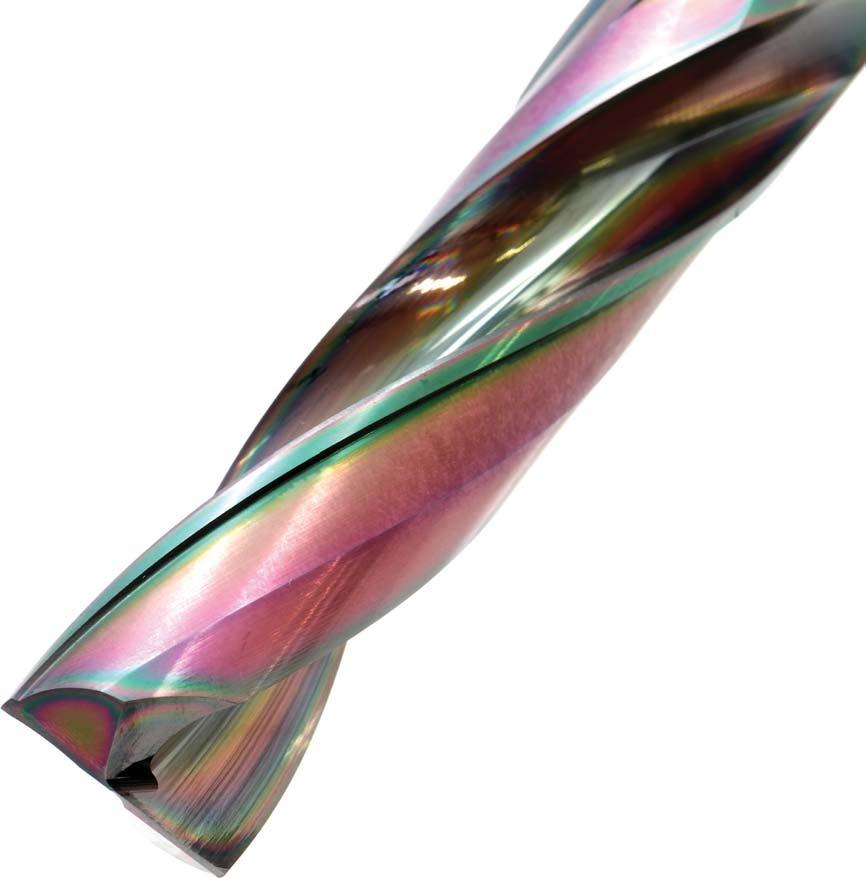


1 Carbide Flat Drills Designed for Various Applications EXOCARB ADF Vol 2


2 Cutting Data Improved Cutting Edge for reduced cutting forces and smaller chip size. Wide Chip Room for superior chip evacuation. Balanced Point Form for stable hole entry. Multi-Purpose Designed for a Wide Variety of Applications The ADF drill is capable of drilling in numerous applications such as inclined surfaces, curved surfaces, flat-bottom holes and more. Burrless Burrless Cross-Hole Inclined Surface Guide Hole Thin Plate Blind Hole for Threading View from top in Curved Surface Curved Exit Surface Through-Hole in Curved Surface Correction of Eccentric Hole Half-Hole in Intricate Position Coating Exceptional Wear Resistance & Toughness Suppresses friction with the wear resistance layer; prevents breakage with the nano periodical layer. Coating Structure Wear-Resistant ayer EXOCARB ADF After drilling 1,620 holes (Still good) After drilling 660 holes (Chipping) Nano Periodical ayer Material: Carbon Steel (1050) Cutting : 246 SFM (3,981 ) Rate: 9.4 IPM (0.002 ) 2 Cutting Data
3 Cutting Data Grey Cast Iron Both EXOCARB ADF Drills and conventional drills show little to no positional inaccuracies when processed over the center of a pre-existing hole. However, when it is necessary to process the drill off-center over a pre-existing hole, the position and straightness of the hole made with the ADF is 5 times more accurate than the conventional drill. Tool Drill Size Machined Surface Work Material Cutting Rate Depth of Hole Coolant Machine Ø18 Flat Surface Grey Cast Iron 246 SFM (1,327 ) 5.2 IPM (0.004 ) 34 mm (Blind) Water Soluble Conventional Horizontal Machining Center Test 1: Centered +Y Ø18 Ø10 Pilot X +X Y Test 2: Offset by 2mm +Y Ø18 Ø10 Pilot X +X 2 mm Y Shift Amount in Hole Position Centered vs Offset Conventional (Centered) Test 2 (2 mm Offset) Half-Hole Carbon Steel (1050) The ADF minimized the amount of shift when drilling a half-hole as compared to both the conventional and competitor drills. View from top Tool Conventional Drill Size Machined Surface Ø12 Flat Surface Work Material Carbon Steel (1050) Cutting Rate Depth of Hole Coolant Machine 121 SFM (979 ) 5.9 IPM (0.006 ) 24 mm (Blind) Water Soluble Horizontal Machining Center Fallen Amount (mm) Based on value of 1 mm from the mouth Conventional 10 mm from the mouth 20 mm from the mouth 6mm 12 Inclined Surface Alloy Steel (4140) The ADF maintained accurate hole position and resisted chipping while drilling on an inclined surface. Tool Drill Size Ø10 Machined Surface Angled Surface (30 ) Work Material Alloy Steel (4140) Cutting Rate Depth of Hole Coolant Machine 200 SFM (1,944 ) 7.7 IPM (0.004 ) 20 mm (Blind) Water Soluble Horizontal Machining Center Number of Holes Holes 770 Holes Corner Chipping Corner Chipping Shift in Hole Position (mm) Shift in Hole Position ADF vs MIN AVE MAX Cutting Data 3
4 High Performance Flat Drill ist 5700 Type 1 Type 2 SPEED FEED P7 EgiAs Tolerance (h8) Size mm inch 2 D 3 +0 / / <D 6 +0 / / <D / / <D / / <D / / EDP Number Flute Overall Shank Fractional Size Wire Gage etter Size mm Inch d / / / / / / / / / /4 - E / / / Packed: 1 pc. Available EgiAs Coating Only. Type 4 EXOCARB ADF
5 High Performance Flat Drill ist 5700 SPEED FEED P7 EgiAs EDP Number Flute Overall Shank Fractional Size Wire Gage etter Size mm Inch d / / / / / / / / / / / / / / / / Packed: 1 pc. Available EgiAs Coating Only. Type ist No Work Material P M K N S H Carbon Steels Alloy Die Steels Steels Stainless Steels Aluminum Nickel ow Med. High Cast Alloy Iron Titanium Hardened Steels PH Casting Inconel 6Al4V (30 ) ~ good best EXOCARB ADF 5
6 High Performance Flat Drill ist 5700 Type 1 Type 2 SPEED FEED P7 EgiAs Tolerance (h8) Size mm inch 2 D 3 +0 / / <D 6 +0 / / <D / / <D / / <D / / EDP Number Flute Overall Shank Fractional Size Wire Gage etter Size mm Inch d / / / / / / / / / Packed: 1 pc. Available EgiAs Coating Only. Type ist No Work Material P M K N S H Carbon Steels Alloy Die Steels Steels Stainless Steels Aluminum Nickel ow Med. High Cast Alloy Iron Titanium Hardened Steels PH Casting Inconel 6Al4V (30 ) ~ good best 6 EXOCARB ADF
7 s & s ist EXOCARB ADF General Drilling Operations Work Material Hardness Drilling Drill Dia. Carbon Steels, Mild Steel 1010, 1050, 1214 Alloy Steels 4140, 4130 Stainless Steels 300SS, 400SS, 17-4PH Cast Iron Ductile Cast Iron SFM SFM SFM SFM SFM mm Inch 2 12, , , , , , , , /8 8, , , , , , , , /16 5, , , , , , , , /4 4, , , , , , , , /8 2, , , , , , , , /16 2, , , , , , , , /2 2, , , , , , , , /8 1, , , , , , , , /4 1, , , , , , , General Drilling Operations Work Material Aluminum Aluminum Alloy Hardened Steel-Pre Hardened Steel Plastic Mold Steel Hardness Up to 50 Up to 40 Drilling SFM SFM SFM SFM Drill Dia. mm Inch 2 22, , , , , , , , /8 14, , , , , , , , /16 9, , , , , , , , /4 7, , , , , , , , /8 4, , , , , /16 4, , , , /2 3, , , , /8 2, , , , /4 2, , , , Note: 1. Water-soluble coolant may be applied as noted in the above table only under the premise that the work surface has been flattened by milling. 2. When using non-water soluble oil or water-emulsifiable (over 20 times dilution), reduce cutting speed by 30%. 3. Use a rigid and precise machine and holder. 4. Please minimize tool hang over as much as possible during machining. 5. Adjust the rotational speed and the feed rate in accordance with conditions such as the machining shape, machine rigidity or work holding. 6. Please set up the drill so that the runout of the cutting edge is under 0.01 mm. 7. When machining an inclined plane, adjust the rotational speed and the feed rate in accordance with the angle of the incline (β). When the machining incline angle(β) is less than 30, please reduce the feed to 40-60%. When the machining incline angle(β) is over 30, please reduce the speed to 60-80%, the feed to 20-40%. 8. Please use step drilling in pilot holes to improve cutting chip separation. 9. If it is necessary to ensure the locating precision of the hole to be machined, adjust the rotational speed and the feed rate as indicated above (in accordance with the machining precision requirement). s & s 7