Previous Lecture. Vacuum & Plasma systems for. Dry etching
|
|
|
- Lorraine Carr
- 5 years ago
- Views:
Transcription


1 Previous Lecture Vacuum & Plasma systems for Dry etching
2 Lecture 9: Evaporation & sputtering Objectives From this evaporation lecture you will learn: Evaporator system layout & parts Vapor pressure Crucible heating techniques Deposition rates Step coverage Multicomponent films
3 Evaporator system Tilt / rotation stage Wafer Charge in crucible Film thickness gauge Wafer shutter
 can easily be measured")

4 Film thickness monitor (FTM) FTM gauge is a piezo-electric quartz crystal. The acoustic self oscillation frequency f 0 (~6 MHz) can easily be measured electrically. f 0 decreases with increasing deposits. The FTM gauge should be positioned to view the crucible even when the wafer shutter is closed. Quartz crystal Shutter Dual head
5 Vapor pressure The generation of vapor pressure is called: Evaporation from a liquid Sublimation from a solid E.g. C Cr Mg Normal deposition rate 0.01 Torr - 1 Torr Ag Sb SiO SnO 2 Vapor pressure ~ 0.1 Torr near the charge
6 Vapor pressure The vapor pressure is local and much higher than the overall chamber pressure. High vapor pressure can generate a virtual source above the crucible. Too high vapor pressure (deposition rates) may cause the vapor to condense prematurely, forming droplets that could hit the wafer and/or FTM. Vapor pressure ~ 0.1 Torr

7 Crucible heating techniques Choice of crucible and heating method depend on the material to be deposited. A poorly chosen crucible material may alloy with the charge. E.g. Al & Ni alloys with W Resistive heating Boats Wire baskets Wire heated crucibles Plated rods Box sources Inductive heating Electron beam heating Focused electron beam Low flux electron beam

8 Resistive heating I


9 Resistive heating Wire basket Chrome plated Tungsten rod


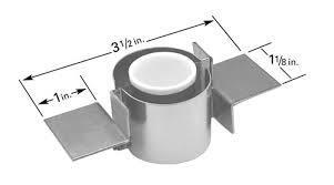
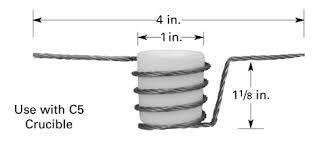
10 Resistive heating Resistive heated crucible


11 Resistive heating Baffled box sources Some charge materials may jump around during sublimation. Use a box with chimney. (Baffled box source) E.g. for SiO

12 Focused electron beam source Single crucible or several crucibles in a linear or revolving indexer. Magnet poles Vapor x-rays E-beam Direct heating of the charge. Temperature gradient from center out. X-ray emission may cause wafer damage. Crucible Emitter
13 Focused electron beam source e - I beam ~300mA B Anode Cathode I fil ~20A Beam shaper U acc ~7kV Beam current control ~
14 Focused electron beam source ~ Long-pos I beam ~300mA Long-sweep B B B Lat-pos e - ~ Lat-sweep I fil ~20A U acc ~7kV Beam current control ~
15 Equilibrium partial vapor pressure Deposition rates Atomic (molecular) flux atoms time area A P e J = P e 2 π k T M Mass evaporation rate (Mass flux) R ME = J M = M 2 π k T P e mass time area Mass loss rate R ML = J M A = mass time M 2 π k T P e A
16 Deposition rates Deposition rate thickness time R R d = J M A 1 1 ρ π R 2 P e A
17 Deposition rates Deposition rate thickness time Φ 1 cosθ cosφ R d = J M A ρ = π R 2 R = M 2 π k T P e A cosθ cosφ ρ π R 2 Θ P e A Most vapor condenses on the chamber walls Big material waste
18 Deposition rates Spherical geometry cosθ = cosφ = R 2 r r Φ Deposition rate thickness time R R d = M 2 π k T P e A 1 ρ 4 π r 2 r Θ Independent of R Φ Θ P e A Many wafers with equal deposition rate Less material waste
19 Deposition rate What is the deposition rate, in the center of the wafer, for gold at a charge temperature of 1500 C and 3cm 2 crucible area? The distance from the charge to the wafer is 40cm cm
20 Deposition rate

21 Step coverage Except for near the source, the vapor travels in straight paths. Strong shadow effect. Poor step coverage. Wafer rotation and wafer heating increase step coverage. Time Wafer heating may also increase film density and film adhesion.


22 Multicomponent films Alloy evaporation Co-evaporation Multilayer evaporation Alloy film Alloy film Conservation of composition requires identical vapor pressure. Correct composition requires well controlled deposition rates. Layers can be heated and alloyed. Example of co- and multilayer evaporation is molecular beam epitaxy. (MBE)
23 Lecture 9: Evaporation & sputtering Objectives From this sputtering lecture you will learn: DC & RF sputter systems Physics of sputtering Sputter yield DC & RF sputter sources Film quality morphology step coverage, stress, etc. Reactive sputtering Ion beam sputter deposition Evaporation / sputtering comparison
24 DC sputter system DC source works for conducting targets only. Source Ar gas inlet Shutter Wafer Difficult to fit a film thickness monitor.
25 RF sputter system RF source works also for non conducting targets. z-match ~ Source Ar gas inlet Shutter Wafer Difficult to fit a film thickness monitor.
26 Physics of DC sputtering Sputtered target atoms Electrons & ions Deposit on the wafer Create new ions through collisions Target (Electrode) Ar Ion impact E Ionization Ar Ar Secondary electron emission Sputtered target atom Wafer
27 Target dependence of sputter yield Sputter yield increases with ion energy but starts to saturate near 1keV. Threshold energy Sputter yield for some target materials depend strongly on the angle of the incident ion. Argon
28 Projectile dependence of sputter yield Highest sputter yield for: Heavy ions Ions with full valence shell 45keV!!!! Much higher than magnetron sputtering. Xe Kr Ne Ar

29 Magnetically confined plasma Review from Lecture 6. E Magnetron, commonly used for sputter deposition sources.

30 Magnetron sputter source DC and RF sources have targets with negative potential. Free electrons try to get away from the target proximity. The escape is less successful where the magnetic field is perpendicular to the escape route. B e -
31 Target erosion The target of a typical magnetron source erodes in a ring pattern. Uneven erosion reduces the lifetime of the target. Uneven erosion may change film thickness uniformity over time. Eroded target area

32 A new gold sputter target will be expen$ive! Target erosion Eroded target area W. Disney

33 Alternative magnetron orientation T Horizontal sputtering Sputter-up

34 Morphology Zone 1: Amorphous, porous film. Zone T: Small grains, smooth and relatively dense film. Zone 2: Tall narrow columnar grains. Moderately rough surface. Zone 3: Large 3-D grains. Moderately rough surface. 3-zone model Movchan & Demchishin Evaporation Example: Au evaporated onto C 1 T 2 3 T/T M = 358K / 1335K = = 0.27

35 Morphology Zone 1: Amorphous, porous film. Zone T: Small grains, smooth and relatively dense film. Zone 2: Tall narrow columnar grains. Moderately rough surface. Zone 3: Large 3-D grains. Moderately rough surface. 3-zone model Thornton T Example: Ti sputtered on 250 C, 7mTorr T/T M = 523K / 1948K = = Pa = 7.5mTorr
36 Directionality Magnetron sputter deposition has low directionality. Target Wafer Table The size of the target is about the same as the distance between the target and the wafer. Approx. 10cm 15cm Most material deposits on the wafer.

37 Step coverage Low directionality Good step coverage Deposition progress of sputtered film All surfaces covered
38 Directionality The deposition directionality can be increased by the use of a collimator. Target Collimator Wafer Table A substantial fraction of target material is wasted.

39 Film stress Compressive film stress The film expands if detached from the wafer. Tensile film stress The film contracts if detached from the wafer.
40 Film stress causes Examples Thermal mismatch Tensile or Compressive The film and the substrate have different thermal expansion coefficients. The deposition is not done at room temperature. Atomic attraction Tensile Atomic attraction seeks to bridge microvoids during deposition. Mechanical deformation Compressive Ion impacts during deposition may cause permanent deformation of the film.
41 Measuring film stress R Wafer with stressed film E T t 2 1 3R 2 = Film stress = Bow change t = Film thickness E = Young s modulus of wafer = Poisson s ratio of wafer T = Wafer thickness R = Wafer radius
42 Reactive sputter system Why reactive sputtering? Examples of reactive sputtering: Variety of films from few targets. Often higher deposition rates. DC sputter deposition of oxides possible. Target Gas Film Si O 2 SiO 2 Si N 2 Si 3 N 4 Ti TiN N 2 Ar gas inlet ~ z-match In/Sn O 2 In 2 O 3 / SnO 2 Process gas inlet (ITO)
43 Ion beam sputter deposition system Wafer Ar gas inlet Ion gun Ar gas inlet Targets Ion gun Widely used for dense, high-quality optical coatings.
44 Evaporation-Sputtering comparison High film density Good adhesion Good step coverage High lift-off compatibility High film thickness uniformity Low material consumption (waste) Low material investments Low x-ray emission In-situ thickness & rate control Good compound deposition control High system layout flexibility E-beam evaporation X X X X Magnetron sputtering X X X X X X X

45 Next Lecture Thin film deposition using Pulsed Laser Deposition