EVALUATION OF INTERCONNECT ALLOYS AND CATHODE CONTACT COATINGS FOR SOFC STACKS
|
|
|
- Jesse Watkins
- 5 years ago
- Views:
Transcription
, Joachim Laatsch and Frank Tietz")

1 ECN-RX EVALUATION OF INTERCONNECT ALLOYS AND CATHODE CONTACT COATINGS FOR SOFC STACKS Nico Dekker and Bert Rietveld (ECN), Joachim Laatsch and Frank Tietz (Forschungszentrum Jülich, Germany) Published in the proceedings of and presented during the 6 th European Solid Oxide Fuel Cell Forum 28 June - 2 July 2004, page 319 Lucerne / Switserland APRIL 2005
2 Evaluation of interconnect alloys and cathode contact coatings for SOFC stacks Nico Dekker and Bert Rietveld Energy research Centre of the Netherlands (ECN), P.O. Box 1, 1755 ZG Petten, Netherlands Joachim Laatsch and Frank Tietz Forschungszentrum Jülich GmbH, Institut für Werkstoffe und Verfahren der Energietechnik (IWV-1), D Jülich, Germany Abstract For the evaluation of interconnect alloys and cathode contact coatings for SOFC stacks, the combinations of 6 alloys and 4 coatings were screened on their resistance during heating up and with time. After 1000 hours at 750 C and 0.6 A/cm², the best interconnect/contact coating combination had a resistance of 8 mωcm² with an increase of <2 mω cm²/1000 hours during 3000 hours. The electrochemical performances of the most promising combinations were tested in combination with Anode Supported Cells (ASC). After 1000 hours, the electrochemical test with the best interconnect/contact coating/cell combination showed a cell voltage of 920 mv with a degradation of <0.6%/1000 hours (750 C, U f =15%, 0.3 A/cm²). Impedance spectroscopy demonstrated that the contact resistance of the cathode interconnect/cell was low, in correspondence with the resistance measurements. Post-test characterization of the samples was carried out by SEM/EDX. It revealed that the resistance of the steel/contact coating assembly depends not only on the thickness of the oxide layer formed on the steel surface during operation but also on the chemical composition of and the phase formation in the oxide layer. The chemical composition of the formed phases is strongly influenced by the elements used in the different steels and contact powders. Introduction The project Component Reliability in Solid Oxide Fuel Cell Systems for Commercial Operation (CORE-SOFC), partly funded by the European Commission within the Fifth Framework Programme, aims at the development of a combination of steel and contact coating for use as a cathode interconnect with low contact resistance and low degradation. Within this part of the project, the contact resistance has been evaluated of several combinations of steels and coating materials. Results will be shown of the contact resistance of various steels with various coatings and the electrochemical performance of cells with coated interconnects. Experimental Six ferritic steels were pre-selected as possible interconnect materials, mainly based on their Thermal Expansion Coefficient (TEC) compatibility with Anode Supported Cells (ASC) and presumed oxidation resistance up to 800 C. Four steels are commercially available (1.4016, , and ) while two steels, ZMG232 and JS-3 (also called Crofer 22 APU), are semi-commercial alloys produced by Hitachi Metals and ThyssenKrupp for SOFC application. The composition of the steels were chemically analysed using ICP-OES and XRF.
3 Four cathode contact powders (LMC, LSC, LSMC and YCM) were produced by Haldor Topsøe (HTAS) using drop pyrolysis. At FZJ the powders were chemically analysed using ICP-OES and crystallographically characterised by X-ray diffraction (XRD). Four-point DC measurements were carried out to obtain the conductivity of the contact materials at different temperatures. An electric current was passed through sintered sticks (5 x 5 x 30 mm 3 ) while the temperature was stepwise reduced from 900 C to room temperature. At each step the voltage was measured to calculate the conductivity in dependence on the temperature. The steel samples were coated at Forschungszentrum Jülich (FZJ) by Wet Powder Spraying (WPS [1]). For the deposition, ethanolic suspensions were made from the powders using commercial dispersants and binders. After WPS the coatings were not sintered. The samples were tested at the Energy research Centre of the Netherlands (ECN) with respect to their contact resistance in a Multiple Interconnect Contact Resistance Unit testrig (MICRU) and their electrochemical performance with an ASC (Single Repeating Unit, SRU). For the measurement of the contact resistance two coated samples of 10 x 10 mm² were placed on top of each other under a clamping force of 1 kg/cm². The samples were heated up with 30 K/h to 850 C, which was kept constant during 3 hours for the in-situ sintering of the coating. After the sintering step the temperature was cooled down with 30 K/h to 750 C and kept constant for hours, simulating the operating conditions of stack tests. The resistance was calculated from the voltage difference between the samples at a current density of 0.6 A/cm². In this MICRU test-rig, four different sets of coated samples could be measured individually in one test-run. For the electrochemical tests, interconnects of 34 x 34 x 3 mm³ were machined with a rib width of 2 mm and a channel width of 2 mm. The depth of the channels was 1.5 mm. The test rig was assembled with an anode interconnect, an ASC and the coated cathode interconnect (SRU). The temperature profile for the in-situ sintering of the cathode contact coating was equal to the contact resistance test. After cooling down to 750 C, the performance of the cell was measured up to 2000 hours under H 2 /4% H 2 O (0.3 A/cm², fuel utilisation of 15%). The total ohmic resistance was measured by impedance spectroscopy. For the electrochemical tests two types of anode supported cells were used, one with LSM cathode (ASC-1) and the other with LSCF cathode (ASC-2). Both type of cells were supplied by Innovative Dutch Electro Ceramics B.V. (InDEC). After testing the contact resistance and electrochemical performance, post-test analysis was carried out at FZJ. Cross sections of each sample were investigated by scanning electron microscopy (SEM) and energy dispersive X-ray analysis (EDX). Results and discussion Basic materials characterization The most important elements of the tested steels are shown in Table 1. The first four steels were selected on base of their increase in chromium content by which the corrosion resistance is higher at elevated temperatures. Additionally, steel was chosen on base of the high Al and Si content, which also increases the corrosion resistance but might increase the electrical resistance of the interconnect by forming an insulating layer. The semi-commercial steels ZMG232 and JS-3 were specially produced with a high chromium but low Al and Si content for application in SOFC stacks.
4 Table 1. Composition of the interconnect steel samples (wt%) Fe Cr Mn Ni Al Si < < < ZMG JS Table 2. Composition of the ABO 3 perovskite cathode contact powders (mol%). A site B site La Sr Y Ca Mn Co target composition LMC LaMn 0.57 Co 0.43 O 3-δ LSC La 0.8 Sr 0.2 CoO 3-δ LSMC La 0.8 Sr 0.2 Mn 0.5 Co 0.5 O 3-δ YCM Y 0.3 Ca 0.7 MnO 3-δ The analysed chemical composition of the cathode contact powders is given in Table 2. Apart from LMC these powders revealed analytical results close to the target compositions. After calcination at 700 C the XRD patterns of all powders showed residues of carbonates which disappeared after calcination at 900 C and pure ABO 3 perovskites were obtained. With the exception of LSC the TEC values (between room temperature and 800 C) of the cathode contact powders were in the range of K -1, which is close to the TEC values of the steels (around K -1 ). The TEC of LSC is K -1, which can cause spallation of the sintered coating from the steel during thermal cycling. The electrical conductivity at 850 C of the sintered YCM and LSMC sample was 100 and 250 S/cm, respectively. The LSC revealed a ten times higher electrical conductivity, while the LMC had an electrical conductivity of about 10 S/cm. Contact resistance measurements All coated steel samples showed a high contact resistance. Thus, steel was excluded from further experiments. For the other coated steel samples, the resistance during heating up was mainly determined by the coating. As an example, the resistance of the JS-3 steel samples coated with the four contact coatings is given in Fig. 1. Over the whole temperature range the LSC-coated sample had the lowest electrical resistance of all. Up to 600 C the resistance of the YCM coated sample was the highest, followed by LSMC and LMC. From 600 C, the resistance of the YCM-coated sample dropped strongly to a value comparable to the LSMC and LSC-coated samples at 850 C (around 6 mω cm²). In contrast, after 600 C the resistance of the LMC-coated sample did not decrease any further, ending at a 10 times higher value than the other samples. Although the LSC samples showed low resistances, it was dropped from further measurements because of the increase of the electrical resistance during the first 200 hours at 750 C and the high mismatch in the TEC with the steels causing spallation of the coating during thermal cycling. Also LMC was dropped due to the high resistance at 750 C.
5 1E+4 1E+3 R (ohm cm²). 1E+2 1E+1 1E+0 YCM 1E-1 1E-2 LSC LSMC LMC 1E Temperature ( C) Fig. 1. Resistance of the coated JS-3 samples during heating up (coated with LMC, LSC, LSMC and YCM). Based on the whole set of measurements the coating materials LSMC and YCM combined with the steels JS-3 and ZMG232 were selected for the long term MICRU test (Fig. 2) Thermal cycle down to 400 C JS3/YCM Resistance (ohm cm²) ZMG232/YCM ZMG232/LSMC Time (hours) JS3/LSMC Fig. 2. Contact resistance of the coated samples with time at 750 C (JS-3 and ZMG232 steel, coated with LSMC and YCM)
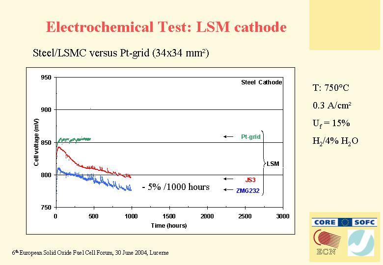
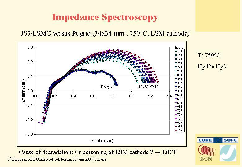
6 The contact resistance of the combination JS3/LSMC after 1000 hours was 8mΩcm² and increased with < 2mΩcm², which was lower than the target value of the CORE-SOFC project. The initial resistance of the JS-3/YCM sample was also low but started to increase exponentially after 350 hours, which was also found in the former short term MICRU tests. The resistances of the ZMG232 samples coated with LSMC and YCM increased strongly during the first 250 hours. After this time, the resistance of the LSMC-coated sample became almost constant, while the resistance of the YCM-coated sample increased gradually. After 2100 hours a not planned thermal cycle occurred with a rate of K/h down to 400 C. The resistance of the JS-3 coated samples appeared to be not affected, while the resistance of the ZMG232 samples was quite unpredictable (see Fig. 2). Therefore it was concluded that JS-3 with LSMC coating is the best combination concerning initial resistance, stability with time and thermal cycling. Electrochemical tests Various combinations of interconnects steels, coatings and cells were tested. A selection of the results is given in Fig Steel Cathode 900 JS3 LSCF Cell voltage (mv) JS3 ZMG232 LSM Time (hours) Fig. 3. Cell voltage with time (LSMC coating, 750 C, 0.3 A/cm², fuel: H 2 /4%H 2 O, U f = 15%). The first measurements were done with ASC-1 (LSM cathode) cells. The performance with steel JS-3 was about 20 mv higher than with steel ZMG232, as measured in former tests. The degradation was about 40 mv/1000 hours. Impedance spectroscopy showed that the degradation was due to an increase of the cathode polarisation resistance, which may be due to Cr poisoning of the LSM cathode. The LSCF cathode is not only said to be less sensitive for Cr poisoning [2, 3], it also has a higher performance at lower temperatures. Therefore, the long-term electrochemical test was performed with an ASC-2 (LSCF cathode) cell in combination with JS-3/LSMC. The initial voltage of this combination was about 920 mv with a degradation rate of <0.6 %/1000 hours during 2300 hours. It was demonstrated by impedance spectroscopy that the higher performance of the ASC-2 cell had to be attributed to the lower cathode polarisation resistance of the LSCF cathode at 750 C.
. 2µm 2µm a) LSMC coating b) YCM coating Intensity [arb.")
![units] 80 70 60 50 40 30 20 10 coating 3 2 1 0 0 1 2 3 4 5 6 7 8 9 10 Profile [µm] steel Sr Mn Co Cr Intensity [arb.](/docs-images/88/115751368/images/7-1.jpg "units] 80 70 60 50 40 30 20 10 coating 3 0 0 1 2 3 4 5 6 7 8 9 10 2 Profile [µm] 1 steel Y Ca Mn Cr c) LSMC coating d) YCM coating Fig. 4. SEM micrographs of cross-sections of steel JS-3 coated with LSMC (a) and YCM (b) with corresponding EDX line scans (LSMC (c), YCM (d)).")
7 Post test analysis Fig. 4 presents SEM micrographs and EDX line scans of cross-sections of steel JS-3 coated with LSMC and YCM from the long-term MICRU tests (see Fig. 2). After a testing time of 3000 hours at 750 C a µm thick corrosion layer formed on the LSMCcoated steel surface (Fig. 4a). 2µm 2µm a) LSMC coating b) YCM coating Intensity [arb. units] coating Profile [µm] steel Sr Mn Co Cr Intensity [arb. units] coating Profile [µm] 1 steel Y Ca Mn Cr c) LSMC coating d) YCM coating Fig. 4. SEM micrographs of cross-sections of steel JS-3 coated with LSMC (a) and YCM (b) with corresponding EDX line scans (LSMC (c), YCM (d)). The dotted lines on the micrographs show the position of the EDX profiles. The corresponding EDX line scan (Fig. 4c) reveals a threefold-layered interface structure with slightly different element distribution. Layer "1", the layer nearest to the steel surface, consists of a chromium-rich Cr-Mn oxide, while the second layer (layer "2") additionally contains Co in approximately the same quantity as Mn. Because of the size of the electron beam no quantitative element detection was possible. In the third layer (layer "3") the quantity of Cr is approximately equal to Mn, the quantity of Co is reduced compared to layer "2" but additionally a Sr enrichment occurs. On the YCM-coated JS-3 steel surface a similar threefold-structured and around 3 µm thick corrosion layer was formed (Fig. 4b). The layer nearest to the steel surface is a chromium-rich Cr-Mn oxide, the second one consists mainly of a Ca-Cr oxide with a small amount of Mn whereas the composition of the third layer is similar to the composition of the coating, may be a more densified region (Fig. 4d). These structures resulted by the evaporation of Cr out of the steel and the migration of Mn from the contact coating into the corrosion layers. Additionally, a small amount of Mn from the steel may migrate into the corrosion layers. The thin black layers between the corrosion layer and the steel surface

, must be due to their compositions.")
8 and the small black areas within the steel consist of Al 2 O 3 and SiO 2, respectively. However, the quantity and thickness of these insulating oxides is too small for affecting significantly the ohmic resistance. Because the thickness of both corrosion layers differs not so much, the differences in the contact resistances, especially the strong increase with time of the YCM-coated steel (Fig. 2), must be due to their compositions. The low ohmic resistance in the case of the LSMCcoated JS-3 steel can be explained with the formation of a dense (Co, Mn, Cr) 3 O 4 spinel which has a low ohmic resistance [4]. Possibly, the Sr enrichment in the third layer increases additionally the conductivity. In contrast, the missing Co content in the corrosion layer of the YCM-coated steel may be responsible for the higher resistances in this case. But also a decomposition of the YCM in the coating can possibly cause the increase of the resistance. This decomposition process forms large particles within the coating consisting of de-mixed Ca- and Y-rich manganites which are only poorly interconnected. This reduces on the one hand the bulk conductivity of the material and on the other hand the conductive area. One of these large particles is shown top left in Fig. 4b. On the SEM micrographs in Fig. 5 cross-sections of the samples of the electrochemical long-term test (1000 hours) are shown (see Fig. 3). As in the contact resistance measurements a corrosion layer composed of (Cr, Mn, Co) oxides formed on both steel surfaces of the interconnects. Because of the shorter testing time the thickness of both corrosion layers is somewhat smaller (around 1 µm) and the enrichment of Sr has not reached the same extent like after 3000 hours. The quantity and shape of the inner corrosion of the ZMG232 steel is due to the higher Al and Si content of this steel (Table 1). Maybe, the higher Al and Si content caused the somewhat lower performance in the electrochemical testing (see Fig. 3). 2µm 2µm a) b) Fig. 5. SEM micrographs of cross-sections of steel JS-3 (a) and ZMG232 (b) from the electrochemical long term tests, both coated with LSMC (see Fig. 3, ASC-1 cell with LSM cathode).
9 Summary The contact resistance and electrochemical performance of a series of interconnect steels, cathode contact coatings and Anode Supported Cells have been tested. After 1000 hours, JS-3 steel in combination with a LSMC coating exhibits a contact resistance of 8 mω cm² at an increase of <2 mω cm²/1000 hours. The electrochemical performance of an Anode Supported Cell with LSCF cathode in combination with an JS-3 interconnect, coated with LSMC, had an initial performance of 920 mv and a degradation <0.6%/1000 hours (750 C, 0.3 A/cm², H 2 /4% H 2 O, fuel utilisation of 15%). One reason for this excellent performance can be found in the formation of a (Cr, Mn, Co) oxide layer on the steel surface which seems to inhibit Cr evaporation from the steel into the cathode by a simultaneously good conductivity at high temperatures. Acknowledgement This work was performed as part of the CORE-SOFC project (contract number ENK5-CT ). We thank the European Commission for partly funding the CORE-SOFC project. References [1] E. Schüller, R. Vaβen and D. Stöver, Thin electrolyte layers for SOFC via Wet Powder Spraying (WPS), Adv. Eng. Mater., 4 (2002) [2] Y. Matsuzaki, I. Yasuda, Dependence of SOFC Cathode Degradation by Chromium- Containing Alloy on Compositions of Electrodes and Electrolytes, J. Electrochem. Soc. 148 (2001) A126-A131 [3] S.P. Jiang, Issues on development of (La,Sr)MnO 3 cathode for solid oxide fuel cells, J. Power Sources, 124 (2003) [4] Y. Larring and T. Norby, Spinel and Perovskite Functional Layers between Plansee Metallic Interconnect (Cr-5 wt% Fe-1 wt% Y 2 O 3 ) and Ceramic (La 0.85 Sr 0.15 ) 0.91 MnO 3 Cathode Materials for Solid Oxide Fuel Cells, J. Electrochem. Soc., 147 (2000)


10


11


12


13


14


15

16
17

18