Magnetic Studies of Multiferroic Heterostructures
|
|
|
- Grace Haynes
- 5 years ago
- Views:
Transcription


1 BearWorks Institutional Repository MSU Graduate Theses Spring 2018 Magnetic Studies of Multiferroic Heterostructures Ahmed Rayhan Mahbub Missouri State Universiy, As with any intellectual project, the content and views expressed in this thesis may be considered objectionable by some readers. However, this student-scholar s work has been judged to have academic value by the student s thesis committee members trained in the discipline. The content and views expressed in this thesis are those of the student-scholar and are not endorsed by Missouri State University, its Graduate College, or its employees. Follow this and additional works at: Part of the Materials Science and Engineering Commons Recommended Citation Mahbub, Ahmed Rayhan, "Magnetic Studies of Multiferroic Heterostructures" (2018). MSU Graduate Theses This article or document was made available through BearWorks, the institutional repository of Missouri State University. The work contained in it may be protected by copyright and require permission of the copyright holder for reuse or redistribution. For more information, please contact BearWorks@library.missouristate.edu.
2 MAGNETIC STUDIES OF MULTIFERROIC HETEROSTRUCTURES A Master Thesis Presented to The Graduate College of Missouri State University TEMPLATE In Partial Fulfillment Of the Requirements for the Degree Master of Science, Materials Science By Ahmed Rayhan Mahbub August 2018
3 Copyright 2018 by Ahmed Rayhan Mahbub ii
4 MAGNETIC STUDIES OF MULTIFERROIC HETEROSTRUCTURES Physics, Astronomy, and Materials Science Missouri State University, August 2018 Master of Science Ahmed Rayhan Mahbub ABSTRACT Multiferroic heterostructures (MHS) consisting of at least two materials with ferroic properties have been a major focus for researchers recently due to its immense potential in device applications. Almost all MHS use ferromagnetic layers making it a very important research area. In this thesis the magnetic properties of different ferromagnetic heterostructures have been investigated. Different bilayers of hard ferromagnet cobalt ferrite (CFO)-soft ferromagnet lanthanum strontium manganese oxide (LSMO) and hard ferromagnet CFO-antiferromagnet nickel oxide (NiO) were fabricated. Pulsed laser deposition technique was used to deposit the thin films on LAO and sapphire substrates. Purpose of using a hard ferromagnetic CFO thin film on top of soft ferromagnetic LSMO and antiferromagnetic NiO was to enhance the multiferroic effects. X-ray diffraction (XRD) analysis on different samples establishes the epitaxial growth of the thin films. Transmission electron microscope (TEM) and scanning electron microscope (SEM) analysis provide the structural and elemental composition of the heterostructure. Superconducting quantum interference device (SQUID) magnetometer was used to perform temperature and field-dependent magnetic properties. At room temperature, ferromagnetic hysteresis loop is observed in all MHS. Presence of CFO increases the coercivity of the LSMO thin film which was one of the goals. In addition, I examined the zero field cooled (ZFC) and field cooled (FC) hysteresis curve for the CFO/NiO bilayer and a shift in the FC curve from the ZFC curve is observed. Studies of these different MHS may guide the development of many novel devices such as actuators, transducers and storage devices. KEYWORDS: ferromagnetism, heterostructures, epitaxial growth, field-dependent magnetic characterization, coercivity. This abstract is approved as to form and content Kartik Ghosh, PhD Chairperson, Advisory Committee Missouri State University iii
5 MAGNETIC STUDIES OF MULTIFERROIC HETEROSTRUCTURES By Ahmed Rayhan Mahbub A Master Thesis Submitted to the Graduate College Of Missouri State University In Partial Fulfillment of the Requirements For the Degree of Master of Science, Materials Science August 2018 Approved: Kartik Ghosh, PhD Ridwan Sakidja, PhD Fei Wang, PhD Julie Masterson, PhD: Dean, Graduate College In the interest of academic freedom and the principle of free speech, approval of this thesis indicates the format is acceptable and meets the academic criteria for the discipline as determined by the faculty that constitute the thesis committee. The content and views expressed in this thesis are those of the studentscholar and are not endorsed by Missouri State University, its Graduate College, or its employees. iv
6 ACKNOWLEDGEMENTS I would like to thank you, my advisor, Dr. Kartik Ghosh for all his help in my research and my two years at MSU. I want to thank my thesis committee members Dr. Ridwan Sakidja, Dr. Fei Wang. I also want to thank my mother, father, sisters and my wife for, without their support and cooperation, my thesis will not be in the shape it is today. I want to thank the Physics, Astronomy, and Material Science Department in MSU for providing a friendly work environment to complete my study. I also want to thank my colleagues Mahmud Reaz, Zach Leuty, Samiul Hasan, Shafiqul Islam, and Sanchali Das for their support towards my thesis completion. v
7 TABLE OF CONTENTS Overview...1 Synthesis and Magnetic Characterization of CFO/LSMO/LAO Heterostructure using Pulsed Laser Deposition...8 Abstract...8 Introduction...8 Experimental...9 Results & Discussion...11 Conclusions...21 Acknowledgments...22 Synthesis and Magnetic Characterization of CFO/NiO/Al2O3 Heterostructure using Pulsed Laser Deposition...23 Abstract...23 Introduction...23 Experimental...25 Results & Discussion...26 Conclusions...37 Acknowledgments...38 Conclusions...39 References...41 vi
8 LIST OF TABLES Table 1. Growth parameters of CFO/LSMO/LAO heterostructures Table 2 Magnetic parameters of CFO/NiO and CFO/NiS heterostructures vii
9 LIST OF FIGURES Figure 1. The unit cell of CFO where Fe 3+ atoms occupy both the octahedral (Oh) and tetrahedral (Td) sites. The octahedral sites are also occupied by Fe 2+, which are replaced by Co 2+ in CFO...3 Figure 2. Unit cell of LSMO where ferromagnetism comes from ferromagnetically aligned Mn-O-Mn chain...4 Figure 3. Unit cell of NiO where (111) planes show how adjacent Ni ions antiparallelly cancel the magnetic moment...6 Figure 4. Schematic diagram of a CFO/LSMO/LAO heterostructure...12 Figure 5. Plot of XRD data for a) sample A and b) sample B. In both cases epitaxial growth of LSMO is observed, but no definite CFO peaks have been observed...13 Figure 6. Plot of XRD data for sample D. Epitaxial LSMO and CFO peaks can be found...14 Figure 7. EDS spectra using SEM. a) EDS spectra of sample C and b) EDS spectra of sample D Figure 8. High resolution TEM-EDS spectra and HAADF image of sample C...16 Figure 9. a) M-H hysteresis loop for sample A: LSMO/LAO thin film. b) Magnified plot of M-H data at low magnetic field Figure 10. a) M-H hysteresis loop for Sample C: CFO/LSMO/LAO heterostructure. b) Magnified plot of M-H data at low magnetic field Figure 11. a) M-H hysteresis loop for Sample D: CFO/LSMO/LAO heterostructure. b) Magnified plot of M-H data at low magnetic field...19 Figure 12. M-H hysteresis loop at room temperature (300 K) for sample D: CFO/LSMO/LAO heterostructure...20 Figure 13. M-H hysteresis loop for the CFO/LAO film at low temperature (5K)...21 Figure 14. Plot of XRD data for the NiO/Al2O3 bilayer. Strong NiO peak has been observed for the (111) plane...27 Figure 15. Plot of XRD data for the CFO/NiO/Al2O3. Strong NiO peaks have been observed for the (111) and (222) planes and CFO peak for the (511) plane...28 viii
10 Figure 16. SEM-EDS spectra of a) a sample with CFO/Al2O3 structure and b) a sample with CFO/NiO/Al2O3 structure...29 Figure 17. SEM-EDS spectra of a) a sample with CFO/NiS/NiO/Al2O3 structure in the 5 micrometer region b) a sample with CFO/NiS/NiO/Al2O3 structure in the 200 micrometer region...30 Figure 18. M-H hysteresis loop for CFO/NiO/Al2O3 heterostructure...31 Figure 19. a) M-H hysteresis loop for CFO/NiO. b) Magnified plot of M-H data at low magnetic field...32 Figure 20. a) M-H hysteresis loop for CFO/NiO at room temperature. b) Magnified plot of M-H data at low magnetic field...33 Figure 21. a) M-H hysteresis loop for CFO at low temperature. b) Magnified plot of M-H data at low magnetic field...35 Figure 22. a) M-H hysteresis loop for CFO/NiS heterostructure at low temperature. b) Magnified plot of M-H data at low magnetic field...36 ix
11 OVERVIEW Multiferroic heterostructures (MHS) have been a major focus for researchers in the recent times. MHS consist of at least two materials with ferroic properties such as ferromagnetism, ferroelectricity, and ferroelasticity. For the last couple of decades ferroelectric-ferromagnetic coupling and ferromagnetic-antiferromagnetic exchange biasing have been the focus of intense research on multiferroics. Magnetoelectric (ME) and multiferroics (MF) possess simultaneously ferroelectric and ferromagnetic properties in the same phase and exhibit linear coupling between them. In such materials the spontaneous magnetization can be switched by an applied electric field and the spontaneous electrical polarization can be switched by an applied magnetic field, due to the cross coupling between ferroelectric (FE) and ferromagnetic (FM) orderings. These structures still maintain all the properties from their respective FE and FM materials, but in addition they offer bifunctional properties. Main advantage of these structures is controlling of charges by applied magnetic fields and spins by applied voltages and using these properties to construct new forms of multifunctional devices [1,2]. The advantage of having both magnetization and electric polarization is used in designing novel devices such as actuators, transducers and storage devices. These types of structures can also be used in multiple-state memory elements by storing information through electric and the magnetic polarizations. Other potential application could be novel memory media which might allow writing of the ferroelectric data bit, and reading of the magnetic field generated by association. [3] 1
12 In order to properly utilize different properties of MHS, magnetic behavior of different materials needs to be properly understood. Almost all MHS use a ferromagnetic material making it an immense topic for researchers. Ferromagnetic materials can be sorted into main two types: soft ferromagnet and hard ferromagnet. The definition of these types depends on their coercivity. For hard ferromagnetic materials coercivity is much higher than soft ferromagnetic materials. Depending on the applications different structures used different ferromagnetic materials [4]. On the other hand, some MHS utilize the unique properties of antiferromagnetic materials. In materials that exhibit antiferromagnetism, the magnetic moments of molecules align in a regular pattern with neighboring spins pointing in opposite directions resulting in net zero magnetization in absence of a magnetic field. Generally, antiferromagnetic order may exist at sufficiently low temperatures. Above a particular temperature, called Neel temperature, antiferromagnetic behavior vanishes [5]. Antiferromagnetic materials occur commonly among transition metal compounds, especially oxides. Antiferromagnetic materials can couple to ferromagnetic materials through a mechanism known as exchange bias. Exchange bias between a ferromagnetic material and an antiferromagnetic heterostructure is an important phenomenon for applications in magnetic random-access memory (MRAM), spin valves, and other spintronic devices [6-7]. In recent years, cobalt ferrite, CoFe2O4 (CFO) has been one of the most dominant research material due to its properties as magnetic nanocrystals and magnetostrictive material. Bulk CFO has high saturation magnetization, high coercivity, high anisotropy, and high magnetostriction [8-12]. CFO thin films maintains most of its bulk properties along with having a high Curie temperature around 800 K [13]. Along with these 2
![properties it is also inexpensive and easy to produce, making it a suitable material for many novel devices such as actuator, sensors, data storage [14-16].](/docs-images/88/116956380/images/13-0.jpg "CFO can operate in the tensile regime without losing magnetic properties due to its anisotropic ability in stress and field annealing [11-12].")
13 properties it is also inexpensive and easy to produce, making it a suitable material for many novel devices such as actuator, sensors, data storage [14-16]. CFO can operate in the tensile regime without losing magnetic properties due to its anisotropic ability in stress and field annealing [11-12]. It also has good mechanical hardness which makes it more suitable magnetic material than conventional piezo-ceramics and other known magnetostrictives. CFO exhibits the highest magnetostriction among all 3-d element based spinal ferrites. Spinal ferrites are ferrimagnetic oxides with a general formula of MFe2O4 (Iron is ferric Fe 3+ and M is a transition metal cation such as Mg 2+, Mn 2+, Co 2+, Ni 2+ ) [17]. Spinal ferrites are widely used in soft high-frequency magnetic materials. They all have high Curie temperature (Tc) except Fe3O4. Structure of CFO is shown in figure 1 where the red ions are oxygen, green ions are Fe3+ and brown ions are Co2+ [18]. In the CoFe2O4 spinel structure, half of the Fe 3+ occupy the Td sites, and eight Co 2+ ions and eight Fe 3+ ions occupy the Oh sites. The Oh and Td sites are represented by brown and green atoms, respectively. Co 2+ and Fe 3+ ions occupying the Oh sites Figure 1. The unit cell of CFO where Fe 3+ atoms occupy both the octahedral (Oh) and tetrahedral (Td) sites. The octahedral sites are also occupied by Fe 2+, which are replaced by Co 2+ in CFO 3
![align parallel to an external magnetic field, and Fe 3+ ions in the Td sites of the FCCpacked oxygen lattice sites are aligned antiparallel to the field [19].](/docs-images/88/116956380/images/14-0.jpg "The total magnetic moment of (Fe 3+ )Td(Co 2+ Fe 3+ )OhO4, thus, arises from the high spin state of Co 2+ in the Oh state as the spin of the Fe 3+ (Oh) and Fe 3+ (Td) ions cancel out.")
14 align parallel to an external magnetic field, and Fe 3+ ions in the Td sites of the FCCpacked oxygen lattice sites are aligned antiparallel to the field [19]. The total magnetic moment of (Fe 3+ )Td(Co 2+ Fe 3+ )OhO4, thus, arises from the high spin state of Co 2+ in the Oh state as the spin of the Fe 3+ (Oh) and Fe 3+ (Td) ions cancel out. CFO has the highest magnetostriction among all of them which makes it a very unique material for magnetic structures. This high magnetostriction property is due to the orbital contribution coming from the presence of Co 2+ ions in the spinal lattice. The value of the magnetostriction depends strongly on the stoichiometry and synthesis method of the CFO material [20]. In this work a commercially purchased CFO target was used to deposit CFO thin films with varying thickness using a physical vapor deposition technique called pulsed laser deposition (PLD). On the other hand, LSMO is a perovskite manganite that have stimulated intense study due to their colossal magnetoresistance (CMR) effect and half-metallic ferromagnetism [21-22]. Figure 2 shows the unit cell of an LSMO structure where the Figure 2. Unit cell of LSMO where the ferromagnetism comes from ferromagnetically aligned Mn-O-Mn chain 4
15 yellow atoms are oxygen, blue atoms are manganese and red atoms are the mixed phase of La1-xSrx. The ferromagnetic behavior comes from ferromagnetically aligned Mn-O-Mn chain [23]. LSMO has a general formula of La1 xsrxmno3, where x describes the doping level. In lanthanum manganese oxides (LaMnO3), lanthanum ions (La 3+ ) are partially substituted with strontium ion (Sr 2+ ) by doping which creates a mixed valence state of Mn 3+ and Mn 4+. This leads in changing magnetic properties from paramagnetic to ferromagnetic and electrical properties from insulating to metal. These transition characteristics can be tuned by controlling the doping concentration of strontium. Due to its half-metallic ferromagnetism and high curie temperature compared to other oxide based magnetic materials LSMO is a very attractive material for spintronics devices [24]. Due to its high-spin polarization arising from conducting electrons LSMO has been widely used for efficient spin injection in organic spin valves, data transfer in magnetic recording systems, read heads in hard disk drives [25-27]. LSMO thin films can be grown in many ways, but PLD technique has been found to be the most suitable synthesis method. The intriguing magnetic and electric transport properties of LSMO are strongly related to the spin-lattice-charge couplings, which are sensitive to the growth conditions of the thin films such as oxygen pressure [28-29]. It is also very sensitive to the strain effect. LSMO grown on different perovskites such as STO, LAO, NdGaO3 has shown different magnetic properties. For example, LSMO grown on LAO substrates exhibits out of plane magnetic anisotropy [30-33]. Additionally, the magnetic and electric transport properties of LSMO also depend on the thickness of the thin films. So, for high quality thin films optimum growth conditions are 5

16 essential. For the first part of the thesis a magnetic heterostructure of CFO and LSMO was synthesized and characterized to observe the effect of CFO on LSMO properties. For the second part of the thesis we investigated the exchange bias effect between the ferromagnetic material CFO and antiferromagnetic material NiO. NiO is a wellknown antiferromagnetic with high Neel temperature of 525 K. There are many fundamental issues related to the metal oxides grown on different substrates regarding their electronic and magnetic properties, which are still being researched now. Figure 3 shows the unit cell of NiO which adopts the NaCl structure. In the figure the adjacent (111) planes are highlighted and, Ni ions occupying the planes are antiparallel and cancels each other magnetic moment [34]. Nickel oxide is an attractive material due to its excellent chemical stability, Figure 3. Unit cell of NiO where (111) planes shows that how adjacent Ni ions antiparallelly cancels the magnetic moment antiferromagnetism, and electron correlations in narrow band systems [35]. It has high magnetic ordering temperature of 520K, a large band gap of 4 ev, and high thermal stability. These properties make NiO a very appealing material for device applications [36]. 6
17 Multiferroic single phase and nanostructure thin films have been produced using a wide variety of grown techniques including sputtering, spin coating, metal-organic chemical vapor deposition (MOCVD), sol-gel process, pulsed laser deposition (PLD), and molecular beam epitaxy (MBE) [37-38]. In this thesis, thin film heterostructures of CFO/LSMO/LAO and CFO/NiO/Al2O3 were fabricated using PLD technique. A further heterostructure of CFO/NiS/ Al2O3 was grown where the NiS layer was created through exchanging oxygen to sulfer of some of the NiO layer using hydrothermal technique. Structural properties were investigated using XRD, TEM and SEM. XRD was performed to analyze the materials in the heterostructures. Multiferroic properties were investigated using a SQUID magnetometer and the effect of the bilayers was analyzed. 7
18 SYNTHESIS AND MAGNETIC CHARACTERIAZATION OF CFO/LSMO/LAO HETEROSTRUCTURES USING PULSED LASER DEPOSITION Abstract I have investigated magnetic properties of CFO/LSMO/LAO hetero-structures. Pulsed laser deposition technique was used to deposit all thin films of the heterostructure. High purity LSMO and CFO targets were used to grow the films. Purpose of using a CFO thin film on a ferromagnetic LSMO was to enhance the multiferroic effects between them. XRD analysis on different samples establishes the epitaxial growth of the thin films. Furthermore, rocking curve analysis along the 002-peak of LAO with XRD was done which indicates out-of-plane alignment and phi-scan analysis confirms the in-plane orientation. TEM and SEM-EDS analysis provide the structural and elemental composition of the hetero-structure. Superconducting quantum interference device (SQUID) magnetometer was used to perform temperature and field-dependent magnetic characterization. At room temperature, ferromagnetic hysteresis loop was observed. Presence of CFO increases the coercivity of the LSMO thin film. In addition, we examine the effect of thickness of CFO thin films on the ferromagnetism of LSMO. Introduction Multiferroic heterostructures or shortly known as MHS consist of at least two materials with ferroic properties such as ferromagnetism, ferroelectricity, ferroelasticity. In recent times research on many MHS has been done by researchers throughout the world. Most of the research on MF materials are concentrated on YMnO3, TbMnO3, DyMnO3, and hexaferrites. These materials show promising MF characteristics but they 8
19 have some drawbacks related to them. Low coercivity, high leakage current, and weak magnetism at room temperature are major difficulties faced by researchers. Currently, researchers have shifted their focus on LSMO. LSMO is a ferromagnetic conductor. It is widely being used on Pb based magnetoelectric heterostructures such as PZT/LSMO. However, one of the main drawbacks of using LSMO is its relatively low coercivity. On the other hand, CFO has been one of the most dominant research material due to its unique properties as magnetic nanocrystalline and magnetostrictive material. Bulk CFO has high saturation magnetization, high coercivity, high magneto-crystalline anisotropy and high magnetostriction coefficient [8-12]. CFO thin films maintain most of its bulk properties along with having a high Curie temperature around 800 K [13]. In this study, a thin layer of CFO was used to enhance the coercivity of LSMO thin films to improve its ferromagnetic properties. We varied the thickness of CFO layer to see the effect on the ferromagnetism of LSMO. Details of the structural-property correlation of CFO/LSMO/ LAO will subsequently be discussed in the result and discussion section. Experimental CFO/LSMO heterostructure were grown on single crystal LAO substrates using PLD technique. High purity dense ceramic targets of LSMO and CFO were purchased from Kurt J. Lesker Company. The LSMO target was 99.9% pure, 1.00" diameter 0.250" thick, +/-0.010" AL. The CFO target was 99.9% pure, 0.70" diameter 0.11" thick. A CMP polished highly oriented (001) LAO substrate (2" dia +/- 0.5 mm 0.5 thickness +/-0.05 mm) was purchased from MTI Corporation. A solid state compact pulsed Nd:YAG laser from Q-smart company was used. It had a wavelength of 266nm, frequency of 10 Hz and energy density of 3-4 J/cm 2. Target to substrate distance was 9
20 fixed at 4 cm. In the optimized synthesis process, an initial layer of LSMO (40000 laser shots at 10 Hz rate) was deposited on LAO substrate at 750 C. For reactive deposition O2 gas was maintained in the chamber and the chamber pressure was 2 x 10⁻¹ mbar. On top of LSMO, CFO was deposited at a temperature of 750 C with oxygen ambient pressure being 2 x 10⁻² mbar. Total number of shots of CFO was varied to get different thickness of CFO. After the desired number of PLD shot, the deposited film was cooled down to room temperature maintaining the oxygen pressure at 110 mbar. The average film thickness of LSMO and CFO thin films were measured by Veeco, Dektak 150. Different samples were prepared by varying the number of laser shots. The crystallinity and crystallographic orientations in the heterostructures were characterized by X ray diffractometer (Bruker AXS D8) equipped with high-resolution Lynx Eye position-sensitive detector using Cu-Kα source with the wavelength of Å) using θ-2θ scan in the range of 20 to 80 maintaining the Bragg Brentano reflection geometry. The data were analyzed through Origin Pro software. The surface morphologies were observed using a scanning electron microscope (FEI Quanta 200) and with a transmission electron microscope (FEI Talos). The sample for cross-sectional TEM analysis was prepared by milling a 5 μm 10 μm rectangular strip that was 100 nm in thickness from the film surface using a focused ion beam (FIB) (JOEL 4500 FIB/SEM) and Pt welding it to a Cu TEM grid. Prior to FIB milling a protective Pt layer was deposited on the film surface to preserve the underlying structures during cross-sectional TEM sample preparation. In both cases, Energy Dispersive X-Ray 10
21 Spectroscopy (EDS) analysis was performed to further investigate the structural properties. Temperature and magnetic field dependent magnetization of the films were measured by a SQUID magnetometer (Quantum Design, MPMS 5XL) equipped with MultiVu software. The temperature was varied from 5K to 350K. The M-H hysteresis loop of the sample was collected by varying magnetic field from Oe to Oe. The sensitivity of the magnetometer was 10-9 emu. All the data were analyzed through Origin Pro software. Result and Discussion 4 different samples were prepared by varying the number laser shots. Table 1 shows the summary of all samples. Table1. No. of samples prepared by varying the no. of CFO shots and their thickness. Sample name LSMO shots LSMO Thickness CFO shots CFO Thickness A nm nm B nm nm C nm nm D nm nm 11
 and LSMO (200) peaks suggests that the layer is epitaxial with the substrate LAO.")
22 Figure 4. Schematic of a CFO/LSMO/LAO heterostructure Figure 4 shows the schematic of the CFO/LSMO/CFO heterostructure. XRD data for the sample A and C are shown in Figure 5. It gives an evidence for an epitaxial growth of LSMO thin films. Presence of LSMO (100) and LSMO (200) peaks suggests that the layer is epitaxial with the substrate LAO. In both cases diffraction peaks of pseudocubic perovskite LSMO are observed. It is evident that no secondary phase is observable within the resolution limits of XRD [39-40]. In case of CFO, no definite peaks are observed although a small CFO can be seen in both samples for CFO (400) peak. Figure 6 shows the XRD data for the sample D in which we used 1000 laser shots on CFO. A clear (400) peak of the face-centered cubic (fcc) CFO phase is observed from the XRD data. [41-43]. Another diffraction peak (620) of CFO is observed which indicates another phase with the increased shots, although the intensity of that peak is very weak compared to the (400) peak. 12
23 LAO 100 LAO 200 Intensity (a.u.) LSMO 012 LSMO 024 LAO Theta LAO 100 LAO 200 Intensity (a.u.) LSMO 012 CFO 004 LSMO 024 LAO Theta Figure 5. XRD data for a) sample A and b) sample B. Both cases epitaxial LSMO is observed but no definite CFO peaks can be found 13
24 1E LAO 100 LAO 200 Intensity (a.u.) LSMO 012 CFO 004 LSMO 024 LAO CFO Theta Figure 6. XRD data for sample D. Epitaxial LSMO and CFO peaks can be found In addition to the XRD analysis we performed the energy dispersive X-Ray spectroscopy (EDS) analysis using scanning electron microscopy (SEM) and transmission electron microscopy (TEM). Figure 7 show the EDS spectrum using the SEM. Spectrum confirms all the elements in the heterostructure. A further detailed EDS analysis was done using the TEM. The sample for cross-sectional TEM analysis was prepared by milling a 5 μm x 10 μm rectangular strip that was 100 nm in thickness from the film surface using a focused ion beam (FIB) (JOEL 4500 FIB/SEM) and Pt welding it to a Cu TEM grid. Prior to FIB milling a protective Pt layer was deposited on the film surface to preserve the underlying structures during cross-sectional TEM sample preparation. 14
 Sample C spectrum which had 2000 CFO shots and b) Sample D spectrum which")


25 (a) (b) Figure 7. EDS spectrum using SEM. a) Sample C spectrum which had 2000 CFO shots and b) Sample D spectrum which had CFO shots Figure 8 shows the EDS spectra of the heterostructure. From the spectra all the elements can be confirmed and the stoichiometry of the heterostructure can be found. This morphology is observable in the HAADF image. The thickness of the individual layers was also measured and they were consistent with the Dektak data. 15

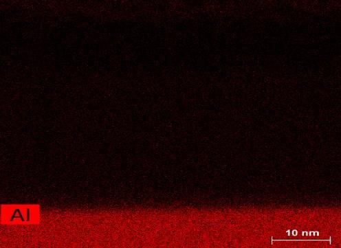


26 Figure 8. A high magnification EDS spectrum using TEM analysis for sample C and the HAADF image. 16
27 Figure 9 shows the magnetic hysteresis loop data for sample A containing only the LSMO/LAO thin films. M-H curve was measured with the field applied parallel to the film plane at low temperature. The magnetization was calculated after subtraction of a diamagnetic background from the substrate. A well behaved ferromagnetic M-H curve was obtained for the LSMO thin film. The magnetization increases until it reaches its saturation value around 500 Oe magnetic field. Coercivity of the LSMO thin film was measured to be 170 Oe. The observed saturation of magnetization value Msat and LAO-LSMO Magnetization(a.u) Coercivity Oe Magnetic Filed,H (Oe) Figure 9. a) M-H hysteresis loop for Sample A of LSMO/LAO. b) Magnified figure for low magnetic field data coercivity Hc for the film are in good agreement with those previously reported for epitaxial LSMO thin films [44-45]. It is worth noting that the magnetic disorder at the surface has been suggested to be considerably larger than in the bulk. In perovskite material, the cubic symmetry lacks at surfaces and charge is transferred from the bulk to 17
28 the surface layers, leading to the formation of Mn3 + [46]. The purpose of using a layer of CFO thin film was to enhance the coercivity of the LSMO thin films as this can lead to better multiferroic structures. For sample B where we had 500 CFO shots (2nm thickness) M-H hysteresis loop was almost like the sample A which led us to believe that such thin layer of CFO could not really affect the overall magnetic response of the heterostructure. Figure 10 shows the magnetic hysteresis loop data for sample C where we deposited 2000 CFO shots yielding 10 nm thickness of CFO. M-H curve was measured with the field applied parallel to the film plane at low temperature. The magnetization was calculated after subtraction of a diamagnetic background from the substrate. A well behaved ferromagnetic M-H curve was obtained. Coercivity of the LAO/LSMO/CFO K Magnetization (a.u.) Coercivity Oe Magnetic Filed,H (Oe) Figure 10. a) M-H hysteresis loop for Sample C of CFO/LSMO/LAO. b) Magnified figure for low magnetic field data 18
29 CFO/LSMO heterostructure was measured to be 360 Oe which is a sharp increase from the value obtained from the previous data. Presence of CFO did increase the coercivity of the structure. CFO is a ferromagnetic insulator which is known for its very high magnetostriction coefficient [47]. The strong development of coercivity with CFO layer thickness is expected based on the increase in total hard magnetic volume in the heterostructure LAO/LSMO/CFO 5K Magnetization (a.u) Coercivity Oe Magnetic Filed,H (Oe) Figure 11. a) M-H hysteresis loop for Sample D of CFO/LSMO/LAO. b) Magnified figure for low magnetic field data M-H curve for sample D where we deposited the highest number of CFO shots of is shown in figure 11. It can be seen that coercivity further increased but not by much. The observed value of the coercivity is 392 Oe. With all the values obtained from the M-H curves for different thickness it can be concluded that with increasing thickness 19
30 we were able to increase the overall coercivity of the heterostructure. Optimum thickness can be determined around 40 nm LAO/LSMO/CFO 300K Magnetization (a.u) Coercivity Oe Magnetic Field, H(Oe) Figure 12. M-H hysteresis loop for Sample D of CFO/LSMO/LAO at room temperature (300K) Figure 12 shows the M-H hysteresis loop for sample D at room temperature(300k). For this measurement high magnetic field data were ignored due to noise and background diamagnetic data were not able to subtract. At room temperature multiferroic effects between CFO and LSMO thin films dominates. A smoothing function was used in ORIGIN to reduce the noise on the data. M-H curve was also measured without the LSMO layer in CFO/LAO thin film. Figure 13 shows the magnetic hysteresis loop for a CFO/LAO thin film structure where 20
31 10000 CFO shots were deposited. It can be seen that at low temperature the diamagnetic properties of LAO thin film dominate LAO/CFO 5K Magnetization (a.u) Magnetic Field, H(Oe) Figure 13. M-H hysteresis loop for CFO/LAO at low temperature (5K) Conclusions We successfully deposited epitaxial LSMO thin films on LAO substrates. On top of LSMO highly oriented CFO thin films of varying thickness were also grown using PLD under oxygen ambient. The XRD data confirm the crystallinity and crystallographic orientations in the heterostructures. The morphology of the structure is confirmed with EDS analysis using SEM and TEM. The well-behaved M-H hysteresis loop at low temperature confirms the ferromagnetic nature of the LSMO thin film with a relatively low coercivity. To overcome the low coercivity of LSMO, CFO was primarily used and the presence of CFO thin films contributes to increase in coercivity of the heterostructure. 21
32 It was confirmed with M-H hysteresis data obtained from different CFO/LSMO heterostructures. From the magnetic data it was confirmed that with increased thickness of the CFO thin films the coercivity continued to increase and optimum coercivity was recorded at 40nm thickness of CFO. However, for room temperature magnetic analysis there were too much noise in the M-H hysteresis loop for high magnetic field. The strong development of coercivity with CFO layer thickness is confirmed based on the increase in total hard magnetic volume in the heterostructure. Acknowledgements I would like to deeply thank the graduate college of Missouri State University, the Wright-Patterson Air Force Base, and the MSU Physics, Astronomy and Materials Science faculty and my colleagues for all their assistance and guidance in data acquisition and analysis. 22
33 SYNTHESIS AND MAGNETIC CHARACTERIAZATION OF CFO/NiO HETEROSTRUCTURE USING PULSED LASER DEPOSTION Abstract We have investigated the magnetic interaction at the interface in CFO/NiO hetero-structures. PLD was used to deposit the thin films on sapphire substrates. Magnetic interaction between a ferromagnetic layer and an antiferromagnetic layer is an important property for giant magnetoresistance which can be used for applications in spin valves, magnetic sensors, and magnetic random access memory. High purity NiO and CFO targets were used. XRD analysis on different samples establishes the epitaxial growth of the thin films. SEM-EDS analysis provided structural and elemental composition of the hetero-structure. SQUID magnetometer was used to perform temperature and field-dependent magnetic properties. To better understand magnetic properties of the heterostructure, zero field cool (ZFC) and field cool (FC) magnetization data were analyzed. At low temperature, ferromagnetic hysteresis loop was observed. A shift in the M-H hysteresis curve was observed for the FC data from the ZFC data which may indicate the presence of exchange bias effect. In addition, we have examined the effect of antiferromagnetic NiS thin films on ferromagnetism of CFO. Introduction Multiferroic structures have been a major focus for researchers in the recent times. Multiferroic structure or shortly known as MF structure consists of at least two materials with ferroic properties such as ferromagnetism, ferroelectricity and ferroelasticity. For the last couple of decades ferroelectric-ferromagnetic coupling and 23
34 ferromagnetic-antiferromagnetic biasing have been the focus of researchers. In materials that exhibit antiferromagnetism, the magnetic moments of molecules align in a regular pattern with neighboring spins pointing in opposite directions resulting in net zero magnetization in absence of a magnetic field. Generally, antiferromagnetic order may exist at sufficiently low temperatures. Above a particular temperature (Neel temperature) antiferromagnetic behavior vanishes [4]. Antiferromagnetic materials occur commonly among transition metal compounds, especially oxides. Antiferromagnetic (AFM) materials can couple to ferromagnetic (FM) materials through a mechanism known as exchange bias. The hard magnetization behavior of an antiferromagnetic thin film causes a shift in the soft magnetization curve of a ferromagnetic film, thereby acting as a reference layer in a magnetic device. This technologically important effect is still poorly understood because of the inability of traditional techniques to spatially determine the microscopic magnetic structure of the AFM thin film. Exchange bias between a ferromagnetic material and an antiferromagnetic heterostructure is an important phenomenon for applications in magnetic random-access memory (MRAM), spin valves and other spintronic devices [5-6]. In this thesis, a thin layer of a ferromagnetic CFO was deposited on top of anti-ferromagnetic NiO to investigate the exchange bias effects between them. We also synthesized NiS and deposited CFO on top of that to make another heterostructure CFO/NiS to see what kind of different exchange bias effect we can have. Details of the structural and magnetic property correlation of CFO/NiO and CFO/NiS will subsequently be discussed in the result and discussion section. 24
35 Experimental CFO/NiO heterostructures were grown on a sapphire substrate using PLD. High purity dense target of CFO was purchased from Kurt J. Lesker Company. The CFO target was 99.9% pure, 0.70" diameter 0.11" thick. NiO target was made from nickel (II) oxide (NiO) powder of 98.0% purity. The powder was first grounded for 2 hours. Polyvinyl alcohol (PVA) was added to prevent agglomeration of the powder particles. The mixture was then pressed at a 10 ton pressure with a hydraulic press to form the target. The prepared target was then sintered at a 1000 temperature C for 24 hours. The rocksalt structure of NiO was confirmed using x-ray diffraction (XRD). A CMP polished highly oriented (0001) sapphire substrate (2" dia +/- 0.5 mm 0.4 thickness +/-0.05 mm) was purchased from MTI Corporation. A solid state compact pulsed Nd:YAG laser from Q- smart company was used. It had a wavelength of 266nm, frequency of 10 Hz and energy density of 3-4 J/cm 2. Target to substrate distance was fixed at 4 cm. In the optimized synthesis process, an initial layer of NiO (25000 laser shots at 10 Hz rate) was deposited on sapphire substrates at 600 C. For reactive deposition O2 gas was maintained in the chamber and the chamber pressure was 2x 10⁻¹ mbar. On top of NiO, CFO (10000 laser shots at 10 Hz rate) was deposited at a temperature of 750 C with oxygen ambient pressure of 2 x 10⁻² mbar. After the desired number of PLD shots, the deposited film was cooled down to room temperature maintaining the oxygen pressure at 110 mbar. Hydrothermal technique was used to synthesize the NiS film. First NiO (25000 laser shots at 10 Hz rate) was grown on sapphire substrates. Then a thiourea (CH4N2S) solution was used with the grown NiO thin film and it was put in the hydrothermal chamber for 24 hours at a temperature of 180 C. NiS thin film was confirmed through 25
36 EDS analysis and then CFO was deposited (10000 laser shots at 10 Hz rate) on top to obtain the CFO/NiS/Al2O3 heterostructure. The crystallinity and crystallographic orientations in the heterostructures were characterized by XRD (Bruker AXS D8 diffractometer) equipped with high-resolution Lynx Eye position-sensitive detector using Cu-Kα source with the wavelength of Å using θ-2θ scan in the range of 20 to 80 maintaining the Bragg Brentano reflection geometry. The data were analyzed through Origin Pro software. The surface morphologies were observed using s SEM (FEI Quanta 200). Energy Dispersive X-Ray Spectroscopy (EDS) analysis was performed to further investigate the structural properties. Temperature and magnetic field dependent magnetization of the films were measured by a SQUID magnetometer (Quantum Design, MPMS 5XL) equipped with MultiVu software. The maximum sensitivity of the magnetometer was 10-9 emu. The M- H hysteresis loop of the sample in field cool (FC) and zero field cool (ZFC) was observed by varying magnetic field from Oe to Oe. For FC hysteresis curve, the thin film was cooled form 350K to 5K in a constant 5000 Oe magnetic field. Temperature dependent magnetization data were taken by varying the temperature form 5K to 350K. The data were analyzed through Origin Pro software. Results and Discussion Figure 14 shows the XRD data for the NiO thin film on a sapphire substrate. Substrate peaks for sapphire (0001) are denoted by the asterisk mark. It can be seen form the XRD plot that NiO thin films were crystalline in nature consisting of a cubic phase. It 26
37 has a strong reflection along the (111) plane. It can be speculated that no secondary phase formations are observable within the resolution limits of XRD [48-49], although a weak reflection along (222) plane could be present but for this sample it was not seen. The d values of the XRD reflections were confirmed with the standard values [50]. Good agreement between the observed and standard d values confirms that the thin film deposited is NiO with a cubic crystal structure NiO 111 * NiO/Al 2 O 3 * Substare Peaks Intensity (a.u.) * Theta (degree) Figure 14. XRD data for the NiO/Al2O3 bilayer. Strong NiO peak can be found for the (111) plane Figure 15 shows the XRD pattern of the CFO/NiO/ Al2O3 heterostructure. Again the substrate peaks are denoted by the asterisk mark. In this case, crystalline NiO (111) and (222) peaks are found. The peak for (222) plane can be seen here in the shoulder of the substrate peak around 80 degree which was not visible in the first XRD pattern. It is 27
38 found that clear (511) peak of the face-centered cubic (fcc) CFO phase can be found [51-53] NiO 111 * CFO/NiO/Al 2 O 3 * Substare Peaks Intensity (a.u.) CFO 511 NiO 222 * Theta (degree) Figure 15. XRD data for the CFO/NiO/Al2O3. Strong NiO peak can be found for the (111) plane and (222) plane. CFO (511) peaks can be seen In addition to the XRD studies we performed the energy dispersive X-Ray spectroscopy (EDS) analysis using SEM. For better imaging and data collection gold (Au) was deposited on top of the thin films using DC sputtering for 10 seconds. Figure 16 shows the SEM-EDS spectra for the CFO/Al2O3 and the CFO/ NiO/Al2O3 structures. It can be seen from the spectra that all the elements are present for their respective thin films. Au counts from the spectrum was removed. (a) 28
 Sample with CFO/Al2O3 structure b) Sample with CFO/NiO/Al2O3 structure EDS analysis was done for the CFO/NiS/ Al2O3 heterostructures.")

39 (b) Figure 16. EDS spectrum using SEM. a) Sample with CFO/Al2O3 structure b) Sample with CFO/NiO/Al2O3 structure EDS analysis was done for the CFO/NiS/ Al2O3 heterostructures. It is shown in figure 17. Sulfur (S) counts was minimal in the first spectrum as it was performed in the 5 micro meter region. A further analysis done in a broader region yielded a more definite sulfur counts. Figure 18 shows the raw magnetization-field data for the CFO/NiS/ Al2O3 heterostructures. The magnetization data for the zero field cool (ZFC) is shown by the red curve and for the field cool (FC) is shown by the black curve. In order to observe the (a) 29
 Sample with CFO/NiS2/ Al2O3 structure in the 5 micrometer region b) Sample with CFO/NiS2/ Al2O3 structure in the 200 micrometer region magnetic data for")

40 (b) Figure 17. EDS spectrum using SEM. a) Sample with CFO/NiS2/ Al2O3 structure in the 5 micrometer region b) Sample with CFO/NiS2/ Al2O3 structure in the 200 micrometer region magnetic data for the CFO/NiO bilayer background magnetic data for just the sapphire substrate was measured and then subtracted. The rest of the magnetic figures are all obtained in the same manner. Figure 19 shows the M-H curve for the CFO/NiO heterostructure with the field applied parallel to the film. The magnetic hysteresis loop for the ZFC is shown by the red curve and for the FC is shown by the black curve. Both of them were measured in low 30
41 CFO/NiO/Al 2 O 3 FC ZFC Magnetization (e.m.u) Magnetic Field (Oe) Figure 18. M-H hysteresis loop for CFO/NiO/ Al2O3 heterostructure temperature (5K). The field applied for the FC data is 5000 Oe. The magnetization was calculated after subtracting the diamagnetic background coming from the substrate sapphire [54]. Figure 19 (b) shows the magnified curve in the low magnetic field region. From the M-H plot it can be seen that there is a shift of coercivity in the FC curve from the ZFC curve to the left of the hysteresis loop. In the negative field region almost 1500 Oe of shift is observed but for the positive field only 300 Oe shift is present. The observed coercivity is around 15 koe. This shift in the M-H curve may be due to the effect of the exchange bias in the interface of the heterostructure. The exchange bias observed in the thin film is low compared to expected value due to the Neel 31
42 (a) CFO/NiO Magnetization (e.m.u) ZFC FC Magnetic Field (Oe) (b) CFO/NiO Magnetization (e.m.u) ZFC FC Magnetic Field (Oe) Figure 19. a) M-H hysteresis loop for CFO/NiO. b) Magnified figure for low magnetic field data temperature of NiO being very high [55]. 32
43 (a) CFO/NiO T= 300K Magnetization (e.m.u) ZFC FC Magnetic Field (Oe) (b) CFO/NiO T= 300K Magnetization (e.m.u) ZFC FC Magnetic Field (Oe) Figure 20. a) M-H hysteresis loop for CFO/NiO at room temperature. b) Magnified figure for low magnetic field data M-H hysteresis curve for room temperature (300K) is shown in the figure 20. There was a lot of noise the high magnetic field region, so the curve is fitted from
44 Oe to Oe field and was reformed using a smoothing function. A ferromagnetic hysteresis curve can be seen. The magnetic hysteresis loop for the ZFC is shown by the red curve and for the FC is shown by the black curve. Even at room temperature, a slight shift in the curve of FC is observed compared to the ZFC to the left. In the negative field region almost 150 Oe of shift is observed but for the positive field only 50 Oe shift is present. Coercivity is measured to be around 2.5 koe. Figure 21 shows the M-H hysteresis curve for the CFO thin film. The magnetization was calculated after subtracting the M-H curve obtained from CFO/Al2O3 thin film. A well-formed ferromagnetic curve can be seen with a high coercivity. The observed coercivity is in good agreement with previously published data [56-57]. The magnetic hysteresis loop for the ZFC is shown by the red curve and for the FC is shown by the black curve. It can be observed that there is a shift in hysteresis curve from the ZFC to FC curve to the left. In the negative field region almost 2000 Oe of shift is observed but for the positive field only 500 Oe shift is present. Coercivity was measured to be around 20 koe. This inherent shift is usually evident in the CFO thin films at low temperatures [58]. The reason is due to the presence of irregular domain patterns in these films which are commonly observed in materials with strong perpendicular anisotropy and high domain wall coercivity [59]. M-H curve for the CFO/NiS/Al2O3 structure was also measured using the SQUID magnetometer. Figure 22 shows hysteresis curve for the heterostructure. A well-behaved ferromagnetism was observed with a high coercivity at low temperature. The magnetization was calculated after subtracting the diamagnetic background coming from 34
45 (a) CFO Magnetization (e.m.u) CFO-ZFC CFO-FC Magnetic Field (Oe) (b) CFO Magnetization (e.m.u) CFO-ZFC CFO-FC Magnetic Field (Oe) Figure 21. a) M-H hysteresis loop for CFO at low temperature. b) Magnified figure for low magnetic field data the substrate sapphire [54]. The magnetic hysteresis loop for the ZFC is shown by the red curve and for FC is shown by the black curve. From the figure 21 (b) there is a shift 35
46 (a) CFO/NiS Magnetization (e.m.u) FC ZFC Magnetic Field (Oe) (b) CFO/NiS Magnetization (e.m.u) FC ZFC Magnetic Field (Oe) Figure 22. a) M-H hysteresis loop for CFO/NiS heterostructure at low temperature. b) Magnified figure for low magnetic field data in hysteresis curve from the ZFC to FC curve to the left. In the negative field region almost 1200 Oe of shift is observed but for the positive field only 150 Oe shift is present. 36
47 Coercivity was measured to be around 13 KOe The Neel temperature of NiS (160K) smaller than that of NiO (Tn =520 K) [57]. So, the thin film with NiO can t be field cooled under the Neel temperature. For that reason, it is difficult to obtain the full extent of the magnetic interaction between CFO/NiO bilayer. Table 2 shows the different magnetic parameters that was observed from different structures. Table2. Saturation magnetization and coercive fields for different samples with different structures for FC data Sample +HC (Oe) -HC (Oe) Coercivity(Oe) Msat (e.m.u.) CFO CFO/NiO CFO/NiS Conclusions We have successfully deposited epitaxial NiO thin films on sapphire substrates. Hydrothermal process was successfully used to grow NiS films on the sapphire substrates. On top of NiO and NiS highly oriented CFO thin films were grown using PLD under oxygen ambient. The theta-2theta scan of the XRD confirms the crystallinity and crystallographic orientations of the heterostructures. The morphology of the structure was confirmed with EDS analysis using SEM. The well-behaved M-H hysteresis loop at low temperature shows a shift in the FC curve from the ZFC curve. So magnetic interaction between the FM and AFM is evident there. A shift in the hysteresis curve in the CFO/NiO bilayer may lead to the possibility of exchange bias effect. CFO/NiO bilayer also exhibits a ferromagnetic hysteresis loop at room temperature with a presence of slight divergence in the FC curve from the ZFC curve. M-H curve analysis also 37