FRP Molded Grating Drop Test Report
|
|
|
- Berenice Briggs
- 5 years ago
- Views:
Transcription


1 Building the World to Last HIGH PERFORMANCE COMPOSITE SOLUTIONS Impact Testing of Various 1-1/2 Deep Walkway Gratings FRP

2 SUMMARY Qualitative evaluation of the ability of fiberglass reinforced plastic (FRP) grating to withstand single and repeated exposure to multiple impacts was conducted during the summer of Several grating specimens of various sizes were exposed to the impact energy of a 340-pound1 object dropped from heights ranging from 24-3/4 to 71-15/16. These tests were conducted in two separate series; the first series were general evaluation tests with minimal data collection. The second series of tests were conducted to collect data. Both film speeds of 64 frames per second and high speeds of 200 frames per second movie cameras were used along with a time marking device and simplified deflection measuring apparatus. The results indicate that single 2 impacts of lower potentials produced mild chipping of the surface meniscus to minor spider web cracking of the surface. Lower surface splintering occurred directly under the impact points when exposed to the higher energy impacts. Repeated exposure3 increased the lower surface local splintering and upper surface crazing and meniscus damage. Total structural failure of the Fibergrate square mesh grating was not experienced in any single or repeated exposure test. Each sample returned to the near unloaded configuration after removal of the test load. manner, demonstrated a level of resistance to impact less than that indicated by Fibergrate products. These tests included galvanized grating as well as other gratings of FRP composite materials. Test results indicated that Fibergrate square mesh grating demonstrates a high degree of impact resistance. Failure of material was limited such that a sufficient residual strength capacity was retained to permit passage over these sections. In every case, the corrosive resistance capability could be recovered by performing minor localized patching and sealing operations. 1.0 INTRODUCTION This report discusses the impact testing of fiberglass reinforced grating and galvanized grating. The purpose of the test was to (a) primarily develop qualitative knowledge on impact performance, (b) to determine the relative capability between the Fibergrate product and various other grating products and (c) extract a certain amount of data that may be of engineering value. Other gratings, when tested in the same 1. Based on actual weight of motor plus guide pole on a platform scale. 2. A single exposure is an event wherein the weight was dropped from an initial release height with multiple rebounds resulting. 3. A repeated exposure is a series of drops onto the same specimen


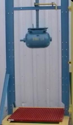
3 to form the vertical guide tower (A) and impact platform (D). The impact head (E) was fitted with a guide pipe (B) and a release mechanism (C) was attached to the tower at the upper level. The test specimen was centered on the projected axis of the guide pipe and was fastened down using standard M clips or A clips. In the first series, deflections were recorded by a scribe-marking system affixed to the edge of the specimen. Still photographs were used to record damage effects. In the second series, deflection as a function of time was recorded by high-speed movie equipment. FIG. 1 - Photograph of Overall Apparatus 2.0 DESCRIPTION In general, a grating sample of approximately 3 x 3 was fixed to a platform such that two opposite edges were simply supported and the other two edges were free. A large electric motor weighing 340 pounds1 (including the guide pipe) was dropped from initial heights varying between 2 to 6 onto the sample. The motor would rebound to decreasing heights approximately eight times on the sample prior to being brought to a stop. The majority of the specimens were exposed to a single event. The test apparatus is shown in Figures 1 and 2 and is constructed along the principle of the guillotine. Structural steel members were used 1. The documentary film indicates a 325-lb weight. This difference is due to inaccuracies between the fish scale used for the movie and the more accurate shipping scale used for the basis of this report. 340 lbs. should be considered to be the more correct value. FIG. 2 - Apparatus Schematic
4 3.0 DISCUSSION The following is a summary of each test in the first series, test numbers 1 through 4, and the observations that were noted: Test No. 1, Sample No. 1: A preliminary test was conducted to evaluate the test apparatus. The test sample was an 1-1/2 deep x 1-1/2 square mesh type D (now Vi-Corr ) grating segment measuring 12 x One side ended in stub bars; consequently, the sample contained eight structural bars. (Tie bars were on the 12 dimension). The sample was placed diagonally on the impact platform using vice clamps and 2 x 4 s (see figure 3). The sample was exposed to a single free fall of 36-3/4. Test No. 2, Sample No. 2: A single 1-1/2 deep x 1-1/2 square mesh Type XFR square segment was tested for grating impact resistance. The test sample measuring 22-3/4 x 40-7/8 (16 tie bars by 28 span bars) was exposed to impacts from drop heights of 24-3/4, 36-3/4 and 48-3/4. For 24-3/4 test, four M clips (Figure 4), secured by a 2-1/2 x 1/4 hex head bolt and nut, was placed in the manner shown in Figure 5. For the 36-3/4 and 48-3/4 test, the M clips were rotated as shown in Figure 6. The first drop was from 24-3/4. Deflection was measured as noted in Table 1 (page 10). Damage to the grating included breaking of the meniscus directly under the impact head and to corner chipping under the M clips. No structural degradation was noted nor was the resin corrosion barrier defeated. The M clips were moved in a distance of one square (about 1-1/2 ) from the corner as shown in Figure 6 and rotated 90 degrees, a clip was added in the middle on each side. The second drop was from 36-3/4. Deflection was measured as noted in Table 1. Significant splintering1 of the bars directly under the impact head on the bottom and out to one side of the mid span was observed. Further damage of the resin system directly under 4 FIG. 3 - Test No. 1, Sample No. 1, Schematic of Test Setup, 1-1/2 Deep x 1-1/2 Square Mesh Type D (Now Vi-Corr ) FIG. 4 - M-2 Hold Down Clip 304 Stainless Steel
5 system. Damage under the clips was minimal. No catastrophic failure was observed. A second drop from the same energy level onto the same test sample was performed. Damage increased, though this increment of increase was less than the original increment caused by the first 60-3/4 drop. After the drop, an additional 420 lbs. (approximately) was added to the weight of the impact head and placed in a static condition on the sample. The test sample continued to provide support to the total 760 lbs. of static loading without significant deflection (less than 50% of grating depth). FIG. 5 - M Clip Orientation for Test No. 2, Sample No. 2 the impact head was noted. Catastrophic failure did not occur. Corrosion protection was defeated but was repairable. Test No. 2, Sample No. 3: A single 1-1/2 deep x 1-1/2 square mesh XFR square mesh segment was exposed to two drops from 60-3/4. The hold down system was three M clips per side. The first drop produced significant splintering on the lower (tension) side of the bars and extensive damage to the upper surface resin 1. For the purpose of this report, splintering refers to a delamination of the glass bundles in the actual direction of the bar. Generally, this splintering did not exceed 2 to 3 in length nor exceed the lower 1/4 of the bar height (Fibergrate products). This normally involved up to three bars directly under the corners of the impact head. FIG. 6 - M Clip Orientation for Test No. 2, Sample No. 3 and Test No
6 Test No. 3, Sample No. 4: A single 1-1/2 deep x 1-1/2 square mesh XFR segment was exposed to three drops, one each from 24-3/4, 36-3/4 and 48-3/4. Hold down was limited to four M clips, one on each corner, aligned in the span direction. Drops from 24-3/4 and 36-3/4 inches produced damage to the meniscus under the impact head only. The drop from 48-3/4 produced additional damage to the resin system directly under the impact head, i.e., crazing of the resin and splintering to a limited area on the tension (lower) side directly under the impact head. No significant structural damage was noted. Test No. 3, Sample No. 5: A 1-1/2 deep x 1-1/2 square mesh XFR segment was exposed to a single impact drop of 71-15/16. Hold down consisted of four M clips, one at each corner, aligned span wise. The impact produced damage to the resin system under the impact head and splintering of the bars on the bottom under the impact head. Again, no significant structural damage was observed. Test No. 4: Samples 6 through 13 in test number 4 were exposed to full height impacts for the purpose of studying hold down clip response, panel size effect, impact head orientation, and span/tie bar orientation. Sample 6 was secured by four M clips, one at each corner and the axis of the impact head was set perpendicular to the free span direction. (Since the impact head is an electric motor, the motor axis becomes a convenient reference.) Further, being basically cylindrical FIG. 7 - A-2 Hold Down Clip 304 Stainless Steel in shape, the distribution of the impact force changes with the relative orientation of the axis with the direction of the free span. Although no specific deflection measurements were taken, deflections under this test were greater than the previous test, as evidenced by witness marks indicating grating contact with the floor (6 maximum deflection). Damage to the grating was again limited to local crazing and splintering on the tension side. Damage was greater than when the axis of the impact head was parallel to the free span. This increase in damage can be attributed to the dynamic contact of the grating with the floor, causing higher compressive forces to be developed in the grating. The M clips remained secured throughout the impact rebound events, although there was permanent deformation and local damage to the grating under the clip
7 Samples 7, 8 and 9 were tested with the axis of the impact head parallel to the free span. Test article size was increased to 48-0 x 38-7/8 dimensions. Each article was exposed to a full-height impact. Sample 7 was secured by four A clips (Figure 7). Upon the first rebound, the A clips sprung open, releasing the sample and allowing it to bounce around. Samples 8 and 9 again were secured with M clips and exposed to full height impacts. Damage was characteristic to the previous test results. Interference between the sample and the impact platform during the event indicated that this size was too large for the test fixture. Consequently, the test article size was standardized to 36-1/4 by 40-7/8 with +1/4 tolerance. Test samples 12 and 13 were competitors grating of equal platform area. Both samples were exposed to full height impacts with the impact axis parallel to the free span. Standard Fibergrate M clips were used to secure the articles. Sample 12 received extensive damage with delamination occurring over the middle 1/3 of the free span through the entire depth of the bar. The delamination occurred between several layers. Sample 13 demonstrated a higher degree of failure than sample 12. Extensive delamination and upper surface crushing resulted. In addition, a significant high velocity spray of surface grit was generated by the grating when impacted. Test No. 5: Test 5 was performed for the purpose of obtaining documentation of gross response, progressive damage and deflection time histories. Samples 14, 15, 16, 18 and 19 were type XFR grating using M clips at each corner. Sample 17 was a typical galvanized steel grating. Each sample was exposed to the fullheight impact. Sample 14 was performed as a familiarization drop for the movie crew, consequently no film was exposed nor data acquired. Sample 15 was used for gross response. Figure 8 is a graph of the response of the impact head during a drop sequence. FIG. 8 - Event No. 2 Rebound Time History


8 Figures 9 and 10 are stills taken during the filming sequences. Figures 11, 12 and 13 are close up views of the upper and lower surfaces damage at the conclusion of the test of sample 16. Figures 14 and 15 are views of the test of the galvanized grating. This grating sustained permanent deformation, approximately 3-3/8, as shown in Figure 14. Numerous welds were cracked and broken at the various intersections of the tie rod and span bar as shown in Figure FIG. 9 - Drop Test Sequence Stills Taken During Filming FIG Drop Test Deflection and Rebound of FRP Grating Taken During Filming. 9 - Drop Test Sequence Stills Taken During Filming


9 FIG Still of Impact Damage to FRP Grating Fig Still of Impact Damage to Steel Grating FIG Closeup of Impact Splintering Fig Closeup of Impact Damage to Steel Grating FIG Closeup of Impact to Clip Area
10 Test No. (date)" 1 (5-19)" 2 (5-26)" 3 (6-2)" Sample No." TABLE 1 IMPACT TESTING OF 1-1/2 DEEP X 1-1/2 SQUARE MESH GRATINGS Sample Description" 1 12 x 48 1/4 Type D; Stub Bar on one end (now Vi-Corr )" /4 x 40 7/8 XFR " Drop Height (h)" TEST LOG DEFL* D" Initial Rebound Height" Remarks 36 3/4 - - Preliminary Test for Equipment checkout Test article suspended diagonally across impact platform. Hold down system of vice clamps and 2 x 4 s. Motor axis in long direction. 24 3/ M clips per side -- one at each corner perpendicular to free span. Motor axis in long direction. 2 Repeat 36 3/4 3-3 M clips per side -- in one bar from edge and one at midpoint parallel to free span. Motor axis in long direction. 2 Repeat 48 3/ M clips per side. Motor axis in long direction /4 x 40 7/8 XFR " 60 3/4 4.28" - 3 M clips per side. Motor axis in long direction. 3 Repeat 60 3/ M clips per side -- static loaded to approximately 800 lbs after test. Motor axis in long direction /4 x 40 7/8 XFR" 36 1/4 x 40 7/8 XFR" 36 1/4 x 40 7/8 XFR" /4 x 40 7/8 XFR" Samples 1 through 5 tested with the tie bar unsupported. 24 3/ M clips per side. Motor axis in short direction. 36 3/ M clips per side. Motor axis in short direction. 48 3/ M clips per side. Motor axis in short direction / M clips per side. Motor axis in short direction. Test No. (date)" "4 (6-2)" "5 (6-8)" Sample No." Sample Description" Drop Height (h)" DEFL* D" Initial Rebound Height" Remarks /4 x 38 3/ / Motor axis turned to be parallel to span. 4 M clips used x 38 3/ / Motor axis parallel to span. 4 A clips used x 40 7/ / Motor axis parallel to span. 4 M clips used x 40 7/ / Motor axis parallel to span. 4 M clips used /4 x 40 7/ / /4 x 40 7/ / /4 x 40 7/ / Competitors Specimen. 4 M2 clips used /4 x 40 7/ / Competitors Specimen. 4 M clips used /4 x 40 7/ / Familiarization Drop for Movie Crew, XFR /4 x 40 7/ / Event #2 in Movie XFR /4 x 40 7/ / Event #3 in Movie XFR x / Galvanized Grating in Movie /4 x 40 7/ / Closeup of Progressive Damage /4 x 40 7/ / Clip Response *NOTE: Deflections are measured at the free end of the specimen and do not represent maximums
11 4.0 RESULTS AND CONCLUSIONS In general, the overall results of these tests indicate that a grating system of composite material construction reacts to an impact condition with a more favorable response than conventional metal gratings. With a complete damping out of the impact motion, the composite grating returns to a near static load, pre-drop configuration. Structural damage would vary from brand to brand and based on these observations appear to be a function of glass content. In general, the higher the glass content, the greater the damage. Obviously, a system with no glass would fail catastrophically. Likewise, a system of pure glass would have no resilience. Hence a case for optimum glass-resin ratio would yield the optimum impact performance can be postulated. Table 2 is a summary of impact damage and relative glass content. The total difference in damage can be attributed in part to the different resin systems. No effort is made herein to analyze these influences. The galvanized steel grating underwent permanent deformation with the initial impact. Welds were broken with the force of the impact. This level of damage would require immediate replacement in service. Test 5, Sample 17 was the galvanized steel grating constructed from flat bar and tie rods welded at each intersection. The drop was from full height. The initial impact caused permanent deformation of the grating to a depth of 3-3/8. A significant number of tie bar welds (about 40%) were broken. Figures 14 and 15 are an overall and closeup view of these results. For dynamic conditions, the M clip type hold downs are better able to withstand these forces. It should be noted that throughout this testing, no standard size panel experienced damage to the extent that pedestrian passage would be restricted. However, fiberglass gratings did suffer different levels of damage. Consequently, the corrosion barrier was defeated to differing levels and life time service remaining in each will be different. Fibergrate XFR appeared to have suffered a lesser degree of corrosion barrier damage, and that damage appears easily repairable. Note: Additional impact testing of the 1-1/2 deep x 1-1/2 square mesh Fibergrate grating was conducted in a cold-temperature environment. Test were run at 28 F and 18 F with a full-height drop. The results of these tests were comparable in terms of damage, to the results noted herein. The temperature for the test reported in the main body of this report was 90 F or greater. TABLE 2 Summary of Impact Damage & Relative Glass Content Type Glass Content Overall Damage Relative to Type XFR Brand A 1.5 A 12 x 9 area under projection of impact head received compressive failure to resin system and glass bundles. Delamination between successive bundles through depth of bars in this area. Brand B 1.4 A 12 x 7 area under projection of impact head received compressive failure of bars and partial separation of material. Significant delamination occurred throughout this area. Type XFR 1.0 In two separate 3 x 3 areas, upper surface meniscus chipping and crazing took place. Lower surface splintering as defined in footnote on page


12 Fibergrate Products & Services Fibergrate Molded Grating Fibergrate molded gratings are designed to provide the ultimate in reliable performance, even in the most demanding conditions. Fibergrate offers the widest selection in the market with multiple resins and more than twenty grating configurations available in many panel sizes and surfaces. Safe-T-Span Pultruded Industrial & Pedestrian Gratings Combining corrosion resistance, long-life and low maintenance, Safe-T-Span provides unidirectional strength for industrial and pedestrian pultruded grating applications. Dynaform Structural Shapes Fibergrate offers a wide range of standard Dynaform pultruded structural profiles for industrial and commercial use, including I-beams, wide flange beams, round and square tubes, bars, rods, channels, leg angles and plate. Dynarail & DynaRound Guardrail, Handrail & Ladders Easily assembled from durable components or engineered and prefabricated to your specifications, Dynarail square tube and DynaRound round tube railing sytems and Dynarail safety ladder systems meet or exceed OSHA and strict building code requirements for safety and design. Custom Composite Solutions Combining Fibergrate s design, manufacturing and fabrication services allows Fibergrate to offer custom composite solutions to meet our client s specific requirements. Either through unique pultruded profiles or custom open molding, Fibergrate can help bring your vision to reality. Design & Fabrication Services Fibergrate Composite Structures Inc. believes the information contained here to be true and accurate. Fibergrate makes no warranty, expressed or implied, based on this literature and assumes no responsibility for the consequential or incidental damages in the use of these products and systems described, including any warranty of merchantability or fitness. Information contained here can be for evaluation only. The marks and trade names appearing herein, whether registered or unregistered, are the property of Fibergrate Composite Structures Inc. Fibergrate Inc Part No /18 Printed in the USA Combining engineering expertise with an understanding of fiberglass applications, Fibergrate provides turnkey design and fabrication of fiberglass structures, including platforms, catwalks, stairways, railings and equipment support structures. Worldwide Sales & Distribution Network Whether a customer requires a platform in a mine in South Africa to grating on an oil rig in the North Sea, or walkways in a Wisconsin cheese plant to railings at a water treatment facility in Brazil; Fibergrate has sales and service locations throughout the world to meet the needs and exceed the expectations of any customer [ ] SAFE Heavy Metal Arsenic Barium Cadmium Chromium Lead Mercury Nickel Selenium Silver ISO QUALITY CERTIFIED F A C I L I T I E S Fax: info@fibergrate.com