TO STUDY THE EFFECT OF PROCESS PARAMETER ON FRACTROGRAPHY ON EN LOW ALLOY STEEL IN SMAW PROCESS
|
|
|
- Alfred Hunt
- 5 years ago
- Views:
Transcription
1 TO STUDY THE EFFECT OF PROCESS PARAMETER ON FRACTROGRAPHY ON EN LOW ALLOY STEEL IN SMAW PROCESS Sandeep Kumar Om Institute of Technology and Management, Hisar M Tech Scholars, Hisar, Haryana, India Umed Khod Om Institute of Technology and Management, Hisar Asst. Prof, Hisar, Haryana, India Ajay Kumar Om Institute of Technology and Management,Hisar Asst. Prof., Hisar, Haryana, India Abstract- Shielded Metal Arc Welding (SMAW) technique applied to low alloy steel of ASTM grade EN which is frequently used in boiler and pressure vessel etc. Welding was carried out according to commercial practice under controlled welding conditions. For SMAW welding technique four work pieces were weld i.e. low heat input, lower medium heat input and medium heat input were examined by Scanning Electron Microscope. During welding with SMAW shielding gas provides inert atmosphere which avoid other gas presented in air to be absorbed by weld pool. Test result came different for different heat input values. At first we broke the work pieces by impact load and then analysis done by SEM. In this paper we will explained the effect of heat input on fractrography and this is directly related to the impact strength of low alloy steel. Under Non-Destructive testing ultrasonic and magnetic particle inspection test was done to check whether the welded piece is free from defect or not. So the main objective of this research is to provide a suitable set on parameters to get a best possible weld with free from defects. Keywords Shielded Metal Arc Welding, Fractrography, Impact strength I. INTRODUCTION Welding is a process of joining two or more pieces of the similar or dissimilar materials to achieve complete coalescence. This is the only method of developing monolithic structures and it is often accomplished by the use of heat and pressure. Although in its present form it has been used since about the beginning of 20th century but it is fast replacing other joining processes like riveting and bolting. At times it may be used an alternative to casting. Thermo-chemical sources, the electric arc or some form of radiant energy can be used to melt the weld metal. In this Vol. 4 Issue 4 November ISSN: X
2 process equipment must be capable of focusing the high-energy heat source on to the weld area. Presently welding is used extensively for fabrication of vastly different components including critical structures like boilers and pressure vessels, ships, off-shore structures, bridges, storage tanks, pipelines, missile and rocket parts, nuclear reactors, fertilizer and chemical plans, earth moving equipment and automobile bodies etc. Welding is also used in heavy plate fabrication industries pipe and tube fabrication. Shielded Metal Arc Welding techniques (SMAW) were applied to ASTM grade EN low alloy steel. Welding was carried out according to commercial practice under controlled welding conditions. For SMAW welding technique four work pieces were weld i.e. low heat input, lower medium heat input and medium heat input were examined by Scanning Electron Microscope. Shielded Metal Arc Welding (SMAW) Shielded Metal Arc Welding (SMAW) or Stick welding is a process which melts and joins metals by heating them with an arc between a coated metal electrode and the work-piece. The electrode outer coating, called flux, assists in creating the arc and provides the shielding gas and slag covering to protect the weld from contamination. The electrode core provides most of the weld filler metal. The Stick welding power source provides constant current (CC) and may be either alternating current (AC) or direct current (DC), depending on the electrode being used. The best welding characteristics are usually obtained using DC power sources. The amperage needed to weld depends on electrode diameter, the size and thickness of the pieces to be welded, and the position of the welding. Generally, a smaller electrode and lower amperage is needed to weld a small piece than a large piece of the same thickness. Thin metals require less current than thick metals, and a small electrode requires less amperage than a large one. It is preferable to weld on work in the flat or horizontal position. However, when forced to weld in vertical or overhead positions it is helpful to reduce the amperage from that used when welding horizontally. Best welding results are achieved by maintaining a short arc, moving the electrode at a uniform speed, and feeding the electrode downward at a constant speed as it melts. Shielded Metal Arc Welding (SMAW) II. Proposed Work Shielded Metal Arc Welding (SMAW) or Stick welding is a process which melts and joins metals by heating them with an arc between a coated metal electrode and the work-piece. The electrode outer coating, called flux, assists in creating the arc and provides the shielding gas and slag covering to protect the weld from contamination. The electrode core provides most of the weld filler metal. The Stick welding power source provides constant current (CC) and may be either alternating current (AC) or direct current (DC), depending on the electrode being used. The best welding characteristics are usually obtained using DC power sources. The amperage needed to weld depends on electrode diameter, the size and thickness of the pieces to be welded, and the position of the welding. Generally, a smaller electrode and lower amperage is needed to weld a small piece than a large piece of the same thickness. Thin metals require less current than thick metals, and a small electrode requires less amperage than a large one. It is preferable to weld on work in the flat or horizontal position. However, when forced to weld in vertical or overhead positions it is helpful to reduce the amperage from that used when welding horizontally. Best welding results are achieved by maintaining a short arc, moving the electrode at a uniform speed, and feeding the electrode downward at a constant speed as it melts. Materials and Methods Shielded Metal Arc Welding (SMAW) techniques were employed on ASTM grade EN low alloy steel. Welding was carried out according to the commercial practice (described in ASME BPVC section IX) under controlled conditions. Material is purchased with its inspection certificate (MTC) which includes the plate size, plate weight and its composition is according to the composition mentioned in ASTM (volume 1). III. Experiment and Result The material used in this study is a commercials grade of EN boiler and pressure vessel steel. Table 1 shows the chemical composition of steel used in this study. Vol. 4 Issue 4 November ISSN: X
3 Table1. Chemical Composition of Base Metal Chemical composition % of grade EN C Si Mn Ni P S Cr Mo V Cu Max Max..4 Max..03 Max..2 Max..3 Max. 1.2 Max..03 Max..3 Joint Preparation:-A "Single Vee Butt Joint" is a common way to prepare thicker metal when a full penetration joint is required. A 60 degree V (30 degrees on each side) is ground into the two plates. A test piece of 150 X 150 X 19 mm, Groove angle was prepared from a large plate of low alloy steel. Test pieces for welding were cut from a large plate and V groove of work piece has been made and using back plate, now at various process parameters welding of these pieces are done. The specimen for various Testing were cut from these welded pieces. Required Amount of Materials Number of samples required for different testing from welded plate as: For Impact Strength testing a specimen 50 mm. in length and 10 mm in the width. No. of specimen required one from each welded plate. Table2. Joint Detail Type of joint Backing Backing Material Type "V" Groove Butt joint Yes Base Material Table3. Position of Weld Position (s) of Groove Welding Progress 1G Horizontal Table4. Technique of weld Travel Speed String or weave Bead Multipass or Single pass Single or Multiple Electrode (S) Detail given below Weave. (Weaving 4 X Ø of Electrode) Multipass Single Electrode During the welding, process of welding, filler electrode, diameter of electrode and current type will remain same filler electrode was of moly herm of diameter 4mm and current type was DC/EP. Introduction of Heat Input:-Heat input is one of the most important process parameters in controlling weld response. It can be referred to as an electrical energy supplied by the welding arc to the weldment. In practice, however, heat Vol. 4 Issue 4 November ISSN: X
4 input can approximately (i.e., if the arc efficiency is not taken into consideration) be characterized as the ratio of the arc power supplied to the electrode to the arc travel speed, as shown in the following equation: Where, I is welding current; V is welding arc voltage; v is the arc welding speed, Q is the heat input Figure 1.Schematic Diagram of Weld Metals Table5. Observed Value of Travel Speed and Heat Input for Welded Test Piece as below: Sr. No. Welded Work Piece Travel Speed (inch/min) Heat input (KJ/mm) 1 Low Heat Input Lower Medium Heat Medium Heat Input High Heat Input Fractrography Analysis For examine the effect of fractrography of heat input work pieces, we took the work pieces from the weld bead and for impact strength test piece is prepared and testing is done. After fracture, analysis is to be done with the help of SEM. Fractrography test is done by the scanning electron microscope. A scanning electron microscope (SEM) is a type of electron microscope that produces images of a sample by scanning it with a focused beam of electrons. The electrons interact with atoms in the sample; producing various signals that can be detected and that contain information about the sample's surface topography and composition Table6. Charpy Test value for LHI, LMHI, MHI & HHI Test Piece Impact Test Charpy J /cm 2 LHI 180 LMHI 162 MHI 86 HHI 76 Vol. 4 Issue 4 November ISSN: X


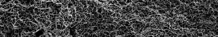
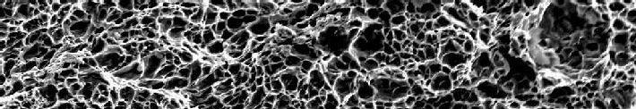


5 SEM Analysis of LHI SEM Analysis of LMHI SEM Analysis of MHI SEM Analysis of HHI Vol. 4 Issue 4 November ISSN: X
6 IV.CONCLUSIONS In the present work, it is concluded that: From the fractrography analysis it can be seen that there is a direct effect on impact strength of gas fractrography value. When heat input is less, then impact test value is more and so decreasing continuously when increase in heat input, there will increases impact properties. So increasing in heat input make the work Piece hard and value of impact load will decrease and SEM captured images can be seen in fig no..low heat input fractured image is coarse and became fine as heat input increase. V. REFERENCE. [1] Ronald J. Parrington, Fractography of Metals and Plastics Practical Failure Analysis,2002. [2] Metals Handbook (8th ed.), Fractography and Atlas of Fractographs, American Society for Metals, Metals Park, OH, [3] U. Portugall and K. Steinlein: Prac. Metallography, pp ,1999. [4] Hidenori Shimazu, Shinji Konosu, Yoichi Tanaka, Yuga Masao, Yamamoto Hiroshi and Ohtsuka Naotake combined effect of temper and hydrogen embrittlement on threshold for hydrogen induced fracture in Cr-Mo steels Journal of Pressure Veseel Technology, [5] V.S.R Murti, P.D Srinivas, G.H.D Banadeki, K.S. Raju Effect of heat input on the metallurgical properties of HSLA steel in multi-pass MIG welding Journal of materials Processing Technology, pp , [6] G. Magudeeswaran, V. Balasubramanian, G. Madhusudhan Reddy, Impact Properties of High Strength Quenched and Tempered Steel Joints Journal of Iron and Steel Research, International, pp , [7] O.M Akselsen., Ø Grong. Prediction of weld metal Charpy V notch toughness materials Science and Engineering: A,pp ,1992. Vol. 4 Issue 4 November ISSN: X