The use of a Inductive Electromagnetic Melt Temperature Sensor to Improve the Injection Molding Process
|
|
|
- Albert Franklin
- 5 years ago
- Views:
Transcription
1 The use of a Inductive Electromagnetic Melt Temperature Sensor to Improve the Injection Molding Process Injection Molding Conference 2017 By Michael F. Durina Md Plastics Incorporated 1361 Wardingley Ave., Columbiana, Ohio fax- (330) mdplastic@msn.com

2

3

4 Temperature is a measure of a quality of a state of a material. The quality may be regarded as a more abstract entity than any particular temperature scale that measures it. What is the Temperature of this Melt? What can you tell about the quality of this Melt by knowing the temperature?

5 Viscosity One of the most important flow properties is the viscosity of a fluid. Plastics are made up of very long molecules; as a result, they have high melt viscosities that are Non- Newtonian in nature and is affected by the ratio of shear stress to shear rate. The viscosity of a plastic is highly dependent on the molecular weight, the higher the molecular weight, the higher the viscosity.
6 Density is the mass divided by the volume. The density of a thermoplastic is affected by temperature and pressure. The density, or specific volume, increases rapidly as the plastic approaches the melting point because the mobility of plastic molecules increases with higher temperatures. As a result, output equations should be performed using the melt density. Density
7 The specific heat is the amount of heat necessary to increase the temperature of one gram of material by one degree Centigrade. In most cases, the specific heat of semicrystalline plastics is higher than amorphous plastics. The amount of heat necessary to raise the temperature of a material from a base temperature to a higher temperature is determined by the Enthalpy difference between the two temperatures. Specific Heat
8 So what does the IMM of today tell us about the Properties of the Polymer?
9 What is Missing is the ability to See and Verify what the Effects the Injection Molding Machine variables have on the Polymer! Melt pressure Hydraulic Pressure Ram Position Injection Time / Flow Rate Temp-Tek Sensor Melt Volume
 by the melt which compresses the sensor area (ᴨ D²) to decrease the bead volume (V).")
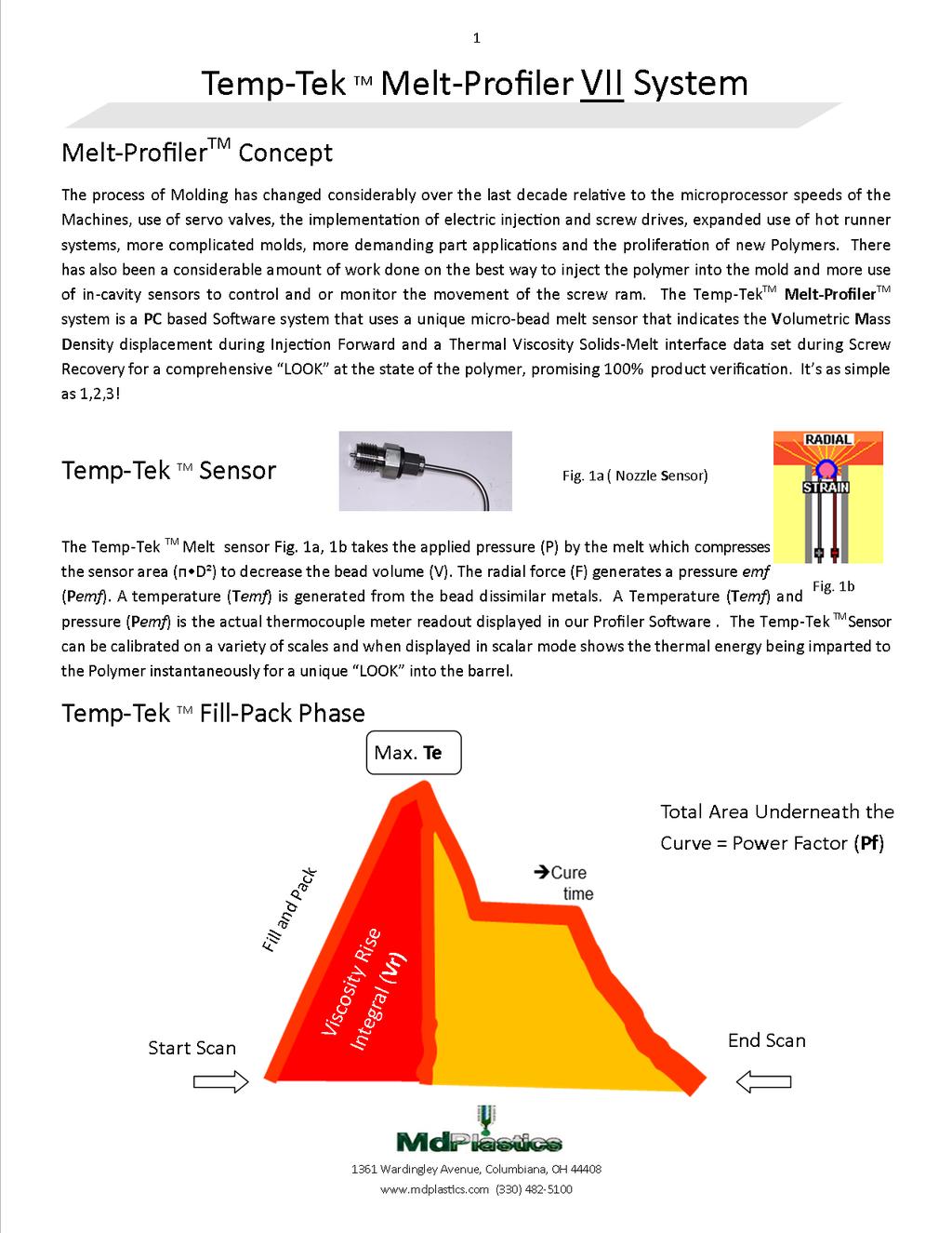
10 The Temp-Tek TM Sensor Patent Holder: Frederick J. Buja US patents 6,649,095 and 7,585,166 The Temp-Tek TM Melt Sensor takes the applied pressure (P) by the melt which compresses the sensor area (ᴨ D²) to decrease the bead volume (V). The radial force (F) generates a pressure emf (Pemf). A temperature (Temf) is generated from the bead dissimilar metals. A Temperature (Temf) Plus pressure (Pemf) is the actual thermocouple meter readout displayed in our Melt-Profiler TM Software for a unique LOOK into the barrel or the Mold Cavity!
11 The 1 st Law of Thermodynamics states: The change in the Internal Energy of a Closed System is equal to the amount of Heat supplied to the system, minus the amount of Work done by the system on its surroundings; E = Q W and A system does work whenever it acts against an external force, re mechanical work due to the expansion or compression of a substance W = P V W = Work P = Pressure V = Specific Volume
12 Properties such as internal energy, enthalpy, specific heat, compressibility and coefficient of volume expansion must be obtained through the defining thermodynamic relationships from P-V-T and calorimetric data. Enthalpy is defined by the equation; H = T (cp) (T1 + T2) Where: cp = specific heat (cal/g- C) T = Change in Temperature C T = Temperature of Polymer C

 mechanical work converted to Heat. 506 504 PF=452.")
13 By placing the Temp-Tek TM Nozzle Sensor into the Melt Stream we read Temperature and when extra mechanical work is performed: Temperature + the change in Enthalpy; H (Cal/g) mechanical work converted to Heat PF=

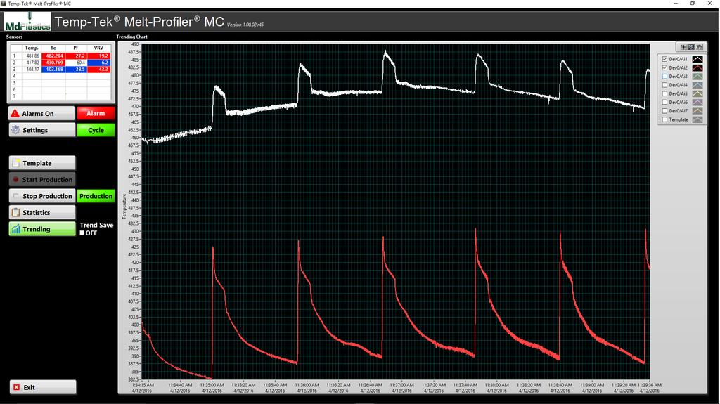
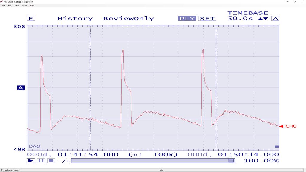
14 Temp-Tek TeMp The cycles shown represent a span of 3 hrs.

15 We conducted extensive testing to determine where the Sensor Bead should be placed within the melt pool.
16
17 The Mold, Machine, Polymer and surrounding environment create a Unique Temp-Tek TM Thermal Template when Making a Good Part PF= 495

18 Upper Left or Upper Right Location Plastic Deposit Location
19 Melt-Profiler TM Math Models: We are Monitoring 3 (three) Control Metrics Screw Recovery and Idle Time Trigger (Inj. Start)
20 Viscosity Rise Integral Viscosity Rise is the Slope from Trigger to Maximum Te vs Time and is a measurement of the Volumetric Mass Displacement. Density
21 Maximum Te 2 3 Maximum Te is the Highest Temp- Tek TM output during the Fill and Pack phase of the Cycle. 1 Trigger (Inj. Start)
22 Power Factor Integral Power Factor (Pf) is the Total Power used during Fill, Pack and Hold. Pf is adjustable to capture more or less Data.
23 The Screw Recovery portion of the Thermal Template should be Consistent for proper Melt Preparation and Uniform Viscosity It is highly unlikely that you will be able to produce quality parts if the Screw Recovery Phase of the Cycle is not Consistent and does not produce a Homogenous Melt!

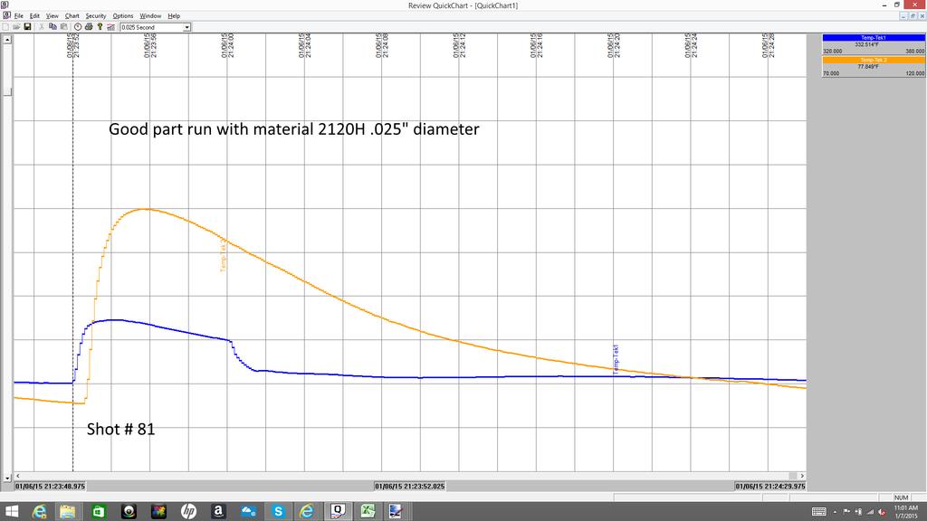
24 This Temp-Tek TM Profile represents the Perfect Thermal Template for this part
25 This Temp-Tek TM Profile represents the Perfect Thermal Template for this part


26 This Temp-Tek TM Profile represents the Perfect Thermal Template for this part
27
28
29

30
31

32 START TO PEAK TIME: 0.65 SEC. Slope-RANGE TEMP: 6.70 F OVERALL CYCLE TIME: SEC. Temp-Tek Nozzle Sensor chart


33 START TO PEAK TIME: SEC. RANGE TEMP: F OVERALL CYCLE TIME: SEC. Pf VALUE: In-Mold Sensor, 1mm diameter flush mount

34


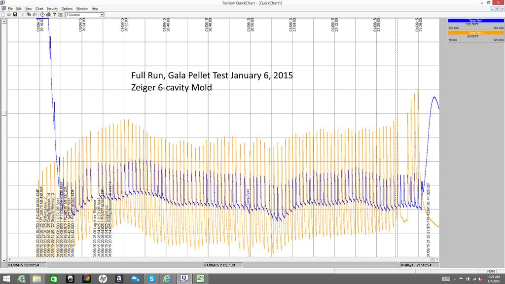
35 Composite portion of Production Run Sodick IMM, 14mm Screw, 12mm Plunger, PPS Material
36
37 Statistical analysis of 29 Good parts yielded Temp-Tek Melt-Profiler Production Run Report the following Data. Date Started: 1/14/2016 Time Started: 1:56:57 PM Date Ended: 1/14/2016 Time Ended: 2:10:16 PM Temp. Units: F Te Data Sensor 8 Minimum: Maximum: Average: PF Data Sensor 8 Minimum: 436 Maximum: Average: 452 We determined that the Alarm Range for Pf should be set between 436 and 465.

38

39


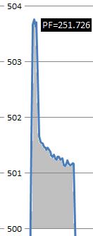
40 Full Pack Melt PF= PF=453.06


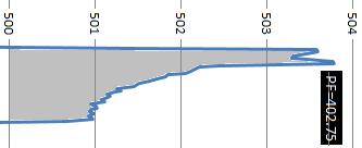

41 near Full Melt PF= PF=402.75


42 Short PF = c


43 Our Pf calculation showed an 11% difference vs. a.9% difference in wt. and.0728mm difference in Stroke. Therefore we are able to discriminate between Good-Bad parts much more effectively than the IMM!! Wt. = 1.11g Wt. = 1.10g Wt. = 1.09g PF= PF= PF=


44 The Temp-Tek Sensor gives us the ability to measure Volumetric Mass Density displacement during the Injection Fill stage of the process which gives us a Significant mathematical Advantage (ᴨ D²) Area of the Cylinder vs. linear position (cushion) in determining a Good Part!
45 NEW State of the Art Process Setup 1. Determine the velocity that is necessary for the Machine that the mold will be processed in so as to assure the optimal fill conditions with regard to fill time, fill pressure and resin temperature while using the nozzle body and nozzle tip selected for the mold. 2. Set the Inject Forward position transfer point from Fill to Pack so that the parts are between 95-98% filled. 3. Conduct a Pack and Hold Analysis 4. Conduct a Gate Seal Analysis 5. Set the Process Save the Perfect Temp-Tek TM Thermal Template 7. Determine the Upper/Lower control limits based on the accumulated Statistics generated by the Melt- Profiler TM Software 8. Lock in the Process 9. Change the Process as needed to accommodate the Changes in the material viscosity, system environment etc. that effect the Temp-Tek TM Thermal Template PF=452.9

46

47
48 NEW Developments/Future 1. Develop a new Software System that incorporates AI programming logic and couple it with an appropriate Hardware System that can read data >1250 hz that utilizes the powerful Pure physics of the Temp-Tek Sensor to assist the molding machine in making Good Parts 2. Develop a NEW Injection unit that is more susceptible to the IoT and Industry 4.0 protocol in collecting Critical data throughout the Cycle.

 of Melt that is dispensed from the Injection Chamber")
49 Why are there Molded Part Variations? 1. Poor Melt Preparation and Homogenization leading to shot-to-shot Variation in the Viscosity. (Quality) 2. Variations in the (Quantity) of Melt that is dispensed from the Injection Chamber due to Decompression deficiencies and or inconsistent NRV closure. Mini-Shut Automatic Shutoff Screw Tip


50 The Inject-eX TM Plasticating unit: a glimpse into the Future of a New Polymer Plasticating and Injection System!!

51 The Inject-eX TM An improved Injection Molding process that employs a non-reciprocating helical plasticating screw housed within a heating cylinder that is coupled to a plunger head assembly, drive housing and motor that prepares and injects molten polymeric material more precisely and efficiently, said components comprising a unitary Inject-eX TM unit.

52 Inject-eX Plasticating Unit

53
54 The new Inject-eX TM Plasticating Unit promises to enhance the Science of Injection Molding by utilizing a State of the Art Posi-Melt TM Stationary Screw and Plunger Assembly that is coupled to a Drive Unit...the whole Assembly reciprocates to displace a precise Mass of polymer into the Mold. Inject-eX TM Features: a. Stationary Posi-MeltTM screw that Provides: b. Consistent Output-Recovery time c. No disruption of Solids Bed Compaction d. Each pellet sees the same Shear History e. Well Dispersed Homogenized Melt Pool f. Smaller Footprint / Output g. Inline Polymer Flow for Less Energy Usage and Pressure Drop h. Precise Shot Control, Mechanical Shutoff Mechanism in Plunger and the use of a Temp-Tek TM Sensor for Melt Density Verification i. Less parts/pieces compared to a Screw/Pot machine design for a smaller Carbon Footprint j. Can be programed to behave like an Injection Blow or Low Pressure Injection unit k. Coupled with an Temp-Tek Sensor, Polymer Mass can be prepared and Displaced precisely