Bollard Application Design Manual
|
|
|
- Shonda Curtis
- 5 years ago
- Views:
Transcription


1 Trelleborg MARINE SYSTEMS Bollard Application Design Manual DESIGN MANUAL


2 Performance People The demanding nature of commercial ports and terminals means you need to connect with a partner that provides much more than technically superior products and technologies. You need to work with a partner that combines best practice expertise gained through worldwide experience with a deep understanding of local requirements and regulations. This global reach combined with feet on the ground local presence helps to make Trelleborg the Performance People that ensure solutions continually enhance your operations. Connect with a partner that provides Performance Assurance services from conception to completion of every project and beyond to maintain and enhance port and vessel performance. Connect with the Performance People, Trelleborg Marine Systems. 1

3 Bollard Application Design Manual Whatever bollard type your application requires, Trelleborg has a range of seven high-performance styles to suit you. Trelleborg bollards are precision engineered and manufactured in a variety of metals including premium grade SG ductile iron and cast steel to offer unprecedented levels of service life and resistance to corrosion and impact. We understand that safety is your number one priority. That s why Trelleborg Marine Systems provides bespoke safety critical bollard, anchoring and fixing solutions quickly, to our customers exact specifications. This guide will provide you with detailed and specific information of our full range of bollard solutions including installation, maintenance and specification advice, plus much more. Contents Bollard Application Design Manual Bollard Range and Technical INFORMATION 5 Bollard Materials and Manufacture 13 Bollard Selection 15 Installation 17 Maintenance 18 Bollard Information 19 2
4 3

5 What end-to-end really means When you choose Trelleborg you ensure your expectations will be met, because we deliver a truly end-to-end service retaining vigilance and full control at every stage. Consultation Consultation to assist you at the earliest stage of your project, with full technical support available from our global office network. Concept Conceptual design in our local office with full knowledge of local standards and regulations, delivered in your language. Design Concepts taken to our Engineering Center of Excellence in India where our team generates 3D CAD designs, application-engineering drawings, bill of materials, finite engineering analysis and calculations. Manufacture Our entire product range is manufactured in-house, meaning we have full control over the design and quality of everything we produce. Our strategically located, state-of-the-art facilities ensure our global, industry leading manufacturing capacity. Testing Across our entire product range, stringent testing comes as standard at every step in our in-house manufacturing process. We ensure that life-cycle and performance of our entire product range meets your specifications, and more. Installation Dedicated project management from solution design right the way through to on site installation support. Global Support Local support on a truly global scale, with customer support teams all over the world. And this service doesn t stop after a product is installed. You have our full support throughout the entire lifetime of your project, including customized training programs, maintenance and on-site service and support. 4

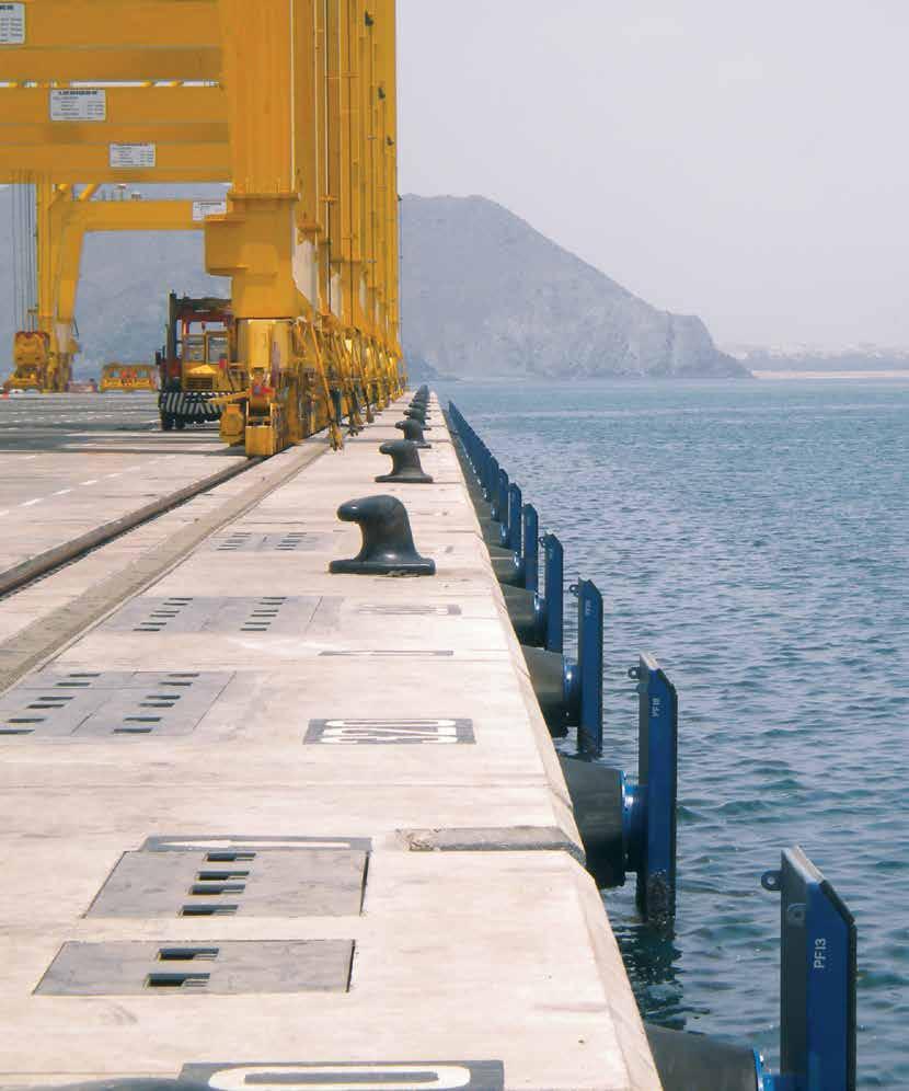
6 Bollard Range And Technical Information Trelleborg bollards come in many popular shapes and sizes to suit most docks, jetties and wharves. They also provide a great deal of flexibility as they can be moved between locations as and when this is required. Standard material is spheroidal graphite (commonly called SG or ductile iron) which is both strong and resistant to corrosion, meaning Trelleborg bollards enjoy a long and trouble free service life. 1 Tee Bollard 2 Horn Bollard 3 Kidney Bollard However, with cast steel remaining popular in specific regions, Trelleborg also manufactures cast steel bollards which provide high impact resistance but require regular painting to prevent corrosion. The shape of Trelleborg bollards has been refined with finite element techniques to optimize the geometry and anchor layout. Even at full working load, Trelleborg bollards remain highly stable and provide a safe and secure mooring. Features High quality SG iron as standard Strong and durable designs Very low maintenance Large line angles possible Standard and custom anchors available 4 Cleat Bollard 6 Single Bitt Bollard 5 Double Bitt Bollard 7 Pillar Bollard 5


7 Tee Bollard Features +75º General purpose applications up to 300 tonnes Suitable for steeper rope angles -15º seaward side Bollard capacity (tonnes) Dimension A B C D E F G ØI J K L L L Bolts M20 M24 M30 M30 M36 M42 M42 M48 M48 M56 M64 M64 Bolt Length P* Quantity P* = bollard base recess mounting depth = hold-down bolt protrusion height [units: mm] 6
 Dimension 15 30 50 80 100 125 150 200 250 A 40 40 50 70 80 80 90 90 120 B 370 410 500 520 570 595 585 660 690 C 400 440 600 660 750 775 850 930 930 D 410 480 640 650 800 820 920")

8 Horn Bollard +75º Features General purpose applications up to 250 tonnes Suitable for steep rope angles Two lines may share a single bollard (subject to bollard capacity) -15º seaward side Bollard capacity (tonnes) Dimension A B C D E F G ØI J K L L L L Bolts M24 M30 M36 M42 M42 M48 M48 M56 M64 Bolt Length P* Quantity P* = bollard base recess mounting depth = hold-down bolt protrusion height [units: mm] 7


9 Kidney Bollard +60º Features General purpose applications up to 200 tonnes Avoid steep rope angles where possible Suitable for warping operations -15º seaward side Bollard capacity (tonnes) Dimension A B C D E F G F+G H ØI J K L Bolts M24 M30 M36 M42 M42 M48 M48 M56 Bolt Length P* Quantity P* = bollard base recess mounting depth = hold-down bolt protrusion height [units: mm] 8
 15 20 25 30 35 seaward side A 30 40 45 45 50 B 165 180 210 250 270 C 510 665 810 960 1120 D 410 510 610 660 840 E 220 280 310 310")

10 Cleat Bollard +60º Features General purpose applications up to 35 tonnes Suitable for steep rope angles Suitable for small wharves or jetties and marinas -15º Dimension Bollard Capacity (tonnes) seaward side A B C D E F G H seaward side J K L Bolt M20 M24 M24 M24 M30 Bolt Length P* Quantity P* = bollard base recess mounting depth = hold-down bolt protrusion height I = 1/2 dimension G [Units: mm] 9
 20 30 50 75 100 125 150 200 A 20 20 25 40 50 60 60 60 B 300 350 420 510 600 700 750 840 C 680 780 950 1140 1330 1535 1670 1860 D 540 610 720 870 1020 1170 1270")

11 Double Bitt Bollard +60º Features General purpose applications up to 200 tonnes Suitable for mooring multiple lines (subject to bollard capacity) Concrete filled (optional) -15º seaward side Dimension Bollard Capacity (tonnes) A B C D E seaward side F G H I J Bolt M20 M22 M30 M36 M42 M42 M48 M56 Bolt Length P* Quantity P* = bollard base recess mounting depth = hold-down bolt protrusion height [units: mm] 10
 -15º seaward side Bollard capacity (tonnes) Dimension 15 30 50 75 100 150 200 A 45 60 70 80 80 100 110 B 370 490 630 740 790 900 1000 C 260 340 450 500 550 650 750 D 220 260 340 390 415")

12 Single Bitt Bollard +75º Features General purpose applications up to 200 tonnes Suitable for steep rope angles Two lines may share a single bollard (subject to bollard capacity) Concrete filled (optional) -15º seaward side Bollard capacity (tonnes) Dimension A B C D E F G H ØI J K M L L Bolt M24 M30 M36 M42 M48 M56 M56 Bolt Length P* Quantity P* = bollard base recess mounting depth = hold-down bolt protrusion height [units: mm] 11
 Dimension 10 15 30 50 75 100 150 200 A 35 40 50 60 70 70 80 90 B 180 280 320 350 380 410 450 480 C 200 300 390 430 500")

13 Pillar Bollard +60º Features General purpose applications up to 200 tonnes Avoid steep rope angles where possible Suitable for warping operations 360 degree horizontal line angle use Can be utilised from all sides of jetty -15º Bollard capacity (tonnes) Dimension A B C ØD P.C.D ØI L Bolt M20 M24 M30 M36 M42 M48 M56 M64 Bolt Length P* Quantity P* = bollard base recess mounting depth = hold-down bolt protrusion height [units: mm] 12
14 Bollard Materials and Manufacture Design Bollards and holding down bolts are designed with a minimum Factor of Safety against failure of 3.0 for SG Iron material grade Designs are typically based on the following: BS 5950:2000 BS 6349: 1-4 (2013): Part 4 AS 3990:1993 Structural Use of Steelwork Marine Structures Mechanical Equipment Design Ductile cast iron is the preferred material for all bollard applications. Grey cast iron is cheaper per unit weight, but the need for thicker wall sections and poor impact strength outweighs this. Cast steel remains popular in some countries but needs regular painting to prevent corrosion. Micro Structure Detailed calculations can be supplied on request. Different factors of safety can be used to suit other national standards and regulations. Materials Trelleborg bollards are offered in Spheroidal Graphite Cast Iron (SG Iron), referred to as Ductile Cast Iron, because of its superior strength and resistance to corrosion. Ductile cast iron combines the best attributes of grey cast iron and cast steel without the disadvantages. Materials Benefits Ductile Cast Iron (Spheroidal Graphite) Grey Cast Iron Cast Steel Lowest service life cost High strength Good impact resistance High corrosion resistance Low cost per weight Excellent corrosion resistance High strength High impact resistance Good cost per weight Disadvantages Low strength Low impact resistance Needs regular maintenance to prevent corrosion The standard material for Trelleborg bollards is ASTM A536 Grade 65/45/12 Spheroidal Graphite Cast Iron. This material has been selected as it has superior corrosion resistance over cast steel and is the best consolidation of price, performance and material strength. Ductile cast iron (SG) Grey iron SG Iron Vs Cast Steel Bollards There is a perception that a stronger material means a stronger bollard. When steel is selected however, the bollards are generally made smaller to achieve the same SWL capacity and safety factors. Smaller bollards have the disadvantage of having a smaller bend radii for the mooring lines. As longevity of mooring ropes is a factor of their loading cycle and bend radii, decreased mooring line life can be expected. Where cast steel bollards must be used, please contact Trelleborg for pricing, availability and lead time. It may be possible to utilize the relevant SG iron pattern for a cast steel bollard. Ductile Cast Iron (Spheroidal Graphite) Lowest service life cost Grey Cast Iron Low cost per weight Cast Steel Good cost per weight High strength Low strength High strength Good impact resistance High corrosion resistance Low impact resistance Excellent corrosion resistance High impact resistance Regular maintenance to prevent corrosion 13
* Grade(s)* Ductile Cast Iron (Spheroidal Graphite Iron) Cast Steel Anchor bolts (galvanized) Blasting (standard) Blasting (high performance) Paint (standard) Paint (high")
15 Material Specification Trelleborg bollards are produced to the highest specifications. The table gives indicative standards and grades but many other options are available on request. Materials Standard(s)* Grade(s)* Ductile Cast Iron (Spheroidal Graphite Iron) Cast Steel Anchor bolts (galvanized) Blasting (standard) Blasting (high performance) Paint (standard) Paint (high performance) BS EN 1563 ASTM A 536 ASTM A148 IS 1030 ISO 898 BS 3692 ASTM SSPC-SP10 NACS no. 2 BS 3416 ISO EN-GJS-450 or or Gr 8.8 (galvanized) Gr 8.8 (galvanized) ASTM F1554 Gr 105 (galvanized) SA2.5 High Build Epoxy (300 microns) * In all cases equivalent alternative standards may apply. Please contact Trelleborg for other grades and high performance paint systems. Quality Assurance Bollards are safety critical items and quality is paramount. Independant 3rd party witnessing of test is available at additional cost on request. A typical quality documentation package will include: Dimensioned drawings of bollard and accessories Bollard and anchorage calculations (if required) Inspection and test plan Certificate of conformance Physical, chemical and materials properties report for casting and anchorages Installation instructions Coating Systems Bollards are supplied as factory standard with a protective coating suitable for most projects. High performance epoxy or other specified paint systems can be factory applied on request in a choice of colors and thicknesses. Standard available coatings include (uncoated, zinc oxide primer or high performance epoxy). Bitumous coatings (Coal Tar) are no longer commercially available and in most countries no longer allowed in marine installation. They have been discontinued on Trelleborg bollards. Bollard are also available and supplied with Hot Dip Galvanized (HDG) on special request basis. High strength stainless steel anchors may be available on request. Wear and abrasion from ropes means paint coatings need regular maintenance. Ductile iron bollards are far less susceptible to corrosion than cast steel bollards, which can rust quickly and will need frequent painting to retain full strength. 14
16 Bollard Selection Selection Bollards should be selected and arranged according to local regulations or recognized design standards. The design process should consider: Mooring pattern(s) Changes in draft due to loading and discharge Wind and current forces Swell, wave and tidal forces Mooring line types, sizes and angles Ice forces (where relevant) Mooring loads should be calculated where possible, but in the absence of information then the following table can be used as an approximate guideline. Displacement Up to 2,000 tonnes Approx. bollard rating 10 tonnes 2,000 10,000 tonnes 30 tonnes 10,000 20,000 tonnes 60 tonnes 20,000 50,000 tonnes 80 tonnes 50, ,000 tonnes 100 tonnes Mooring Line Angles Mooring line angles are normally calculated as part of a comprehensive mooring simulation. Standards and guidelines such as BS6349: Part 4, ROM and PIANC suggest mooring line angles are kept within the limits given in the table below. In some cases much larger line angles can be expected. Trelleborg bollards can cope with horizontal angles of ±90 and vertical angles up to 75. Please check with your local office about applications where expected line angles exceed those given in the table as these may need additional design checks on anchorages and concrete stresses. Suggested Line Angles (BS6349, ROM , PIANC) Head & stern lines* 45 ±15 Breast lines* 90 ±30 Spring lines* 5 10 Vertical line angle ( ) <30 * Relative to mooring angle 100, ,000 tonnes 150 tonnes over 200,000 tonnes 200 tonnes Where strong winds, currents or other adverse loads are expected, bollard capacity should be increased by 25% or more
 or alternatively surface mounted. Once the grout has reached full strength, anchors can be fully tightened.")
17 Installation Introduction Bollards must be installed correctly for a long and trouble-free service life. Anchors should be accurately set out with the supplied template. Bollards can be recessed (as shown) or alternatively surface mounted. Once the grout has reached full strength, anchors can be fully tightened. Mastic is often applied around exposed threads to ease future removal. Fixing Options Recess Mounting Type Retrofit Mounting Type (using EC 2 epoxy anchors) Concrete Recess Surface Mounting Type Steelwork Mounting Type *refer to dimensions tables Recessing the bollard is generally recognized as superior to surface mounting. Recessing the base prevents the bollard from working loose on its bolts or cracking the grout bed especially relevant for high use locations. Through Bolting Type 17


18 Maintenance Like all equipment in the marine environment, regular inspection and maintenance is critical to achieving maximum life expectancy. Trelleborg recommends a regular scheduled inspection of equipment such as bollards as part of any berth. Key items that need to be focussed on during the inspection and maintenance include: Protective Coating Bollards are supplied as factory standard with a protective coating suitable for most projects. High performance epoxy or other specified paint systems are usually applied at the factory on request in a choice of colors and thicknesses. Wear and abrasion from ropes means paint coatings need regular maintenance. Like all epoxy coating systems, maintenance is integral to increasing life expectancy. Trelleborg recommends regular inspection of the bollards Repair and upkeep of the coating system is dependant upon the coating system selected. Trelleborg tries to utilize commercially available coating systems to ensure local products can be sourced and system repair procedures are in line with the coating system manufacturers guidelines. Grout Installation and grout filling requires extra care to avoid damage to factory applied coatings. Similarly regular inspection and possible repair of grout under and around the bollard is critical to the ongoing integrity of bollard performance. Should grout be cracked or damaged, it is recommended that it be replaced. Hold Down Bolts Holding down bolt anchor sets are crucial to bollard performance. Nuts shall be tightened using full manual effort with a 1m long spanner extension to approximately 200Nm. Ensuring correct torque settings will ensure bollards and hold down bolts achieve optimum performance. These are critical to be checked during installation. Visual checks on hold down bolts should be undertaken during regular maintenance to ensure no loosening of bolts has occurred. Bollard Materials Ductile iron bollards are far less susceptible to corrosion than cast steel bollards, which can rust quickly and will need frequent painting to retain full strength. Regular inspection of the bollard materials is recommended. Trelleborg is happy to assist in providing inspection services on berthing and mooring equipment. 18
19 Bollard Information Standard Designs The standard bollard range has been developed based on the requirements of many facilities throughout the world. Some clients may request different designs based on familiarity, history, etc. However the Trelleborg range meets most functional mooring requirements. The ReadyMoor and SmartMoor Quick Release Hooks are also available for instances where a more advanced safety solution is required. Custom Designs As well as our standard bollard range, we also offer custom-built bollards. Whatever your project, we will design and deliver bespoke solutions to your exact specifications. Calculations Bollards are provided with engineering calculations, which describe bolt group pullout forces, shear loadings and bolt tensions. Jetty Design The suitability of a new or existing jetty design to include bollards as part of the structure should be verified by appropriately qualified marine structural engineers or consultants. This includes concrete or steel structure reinforcement for additional tensile and shear loads, reduced edge distances, and fastening/ anchor-bolt arrangements. Jetty Construction Materials Calculations are based on a concrete strength of 40MPa as this is commonly used at many new facilities. A higher safety factor has been applied to the concrete strength to allow for special variations in jetty structures, which means that it is acceptable to use 30MPa concrete. However, the safety factor for this part of the system is reduced. Final design of the jetty including steel reinforcement, edge distances, shear bracing and concrete strength is always the responsibility of the jetty designer. Bollard Selection The engineering required to select, locate and orientate bollards is dependent on a range of parameters including vessel size, local weather, bathometry, currents, tides and the jetty configuration. The analysis to determine the layout of the jetty is the responsibility of the jetty designer and not the bollard supplier. Technical Support Technical advice, design and enquiries should be directed to your local Trelleborg Marine Systems office. Grout Type Trelleborg recommends a non shrink grout, either cementious or epoxy type, with a minimum compressive strength of 60MPa. For recessed bollards, Trelleborg recommends low viscosity high flow grouts to ensure full penetration around and under the base plate. Holding Down Bolt Specification The holding down bolts are described in the product list and each general arrangement drawing. The bolts are all ISO Grade 8.8 and hot dip galvanized, with one nut and washer set. It should be noted that as bollard bolts are so large that the testing criteria in most fastener codes are therefore not applicable. Proportional testing methods are used at half the bolt radius according to ASTM F606. Holding Down Bolt Grades Standard bollards use Grade 8.8 bolts only. Alternative bolt materials can be used but require re-engineering, including calculations and drawings. Any modification to holding down bolt materials should be reviewed and approved by a qualified and certified engineer. 19

20 Breakaway Bollards Due to the magnitude of the loads applied to bollards, it is extremely dangerous to have them breakaway in an uncontrolled manner. Due to variations in material properties and tolerances, it is impossible to calculate actual breakaway load, making it highly unpredictable. Numerous injuries, deaths and damage to equipment have occurred due to broken mooring lines and mooring equipment. As a responsible manufacturer, Trelleborg Marine Systems will not recommend these types of devices. Use of Anchor Plates Extensive testing by European, Australian and American design institutes has determined that a standard bolt head will produce the same pullout cone as similar bolts with an anchor plate. Trelleborg does not provide anchor plates with their standard bollard systems. Anchor plates may be added if required without any detriment to the system. Load Testing Trelleborg does not carry out any physical load testing of bollards. The bollards and holding down bolt systems are designed to sustain the applied tension and shear with adequate safety factors and physical testing is considered unnecessary. Materials Testing Codes and Guidelines ACI Building Code Requirements for Structural Concrete A - Appendix D, Anchoring to Concrete BS6349: 1-4 (2013): Part 4 Code of Practice for Design of Fendering and Mooring Systems EAU (2004) Recommendations of the Committee for Waterfront Structures ETAG 001 (1997) Guideline for European Technical Approval of Metal Anchors for use in Concrete Ministry of Transport, Japan (1999) Technical Note No.911 Ship Dimensions of Design Ships under given Confidence Limits PIANC Report of PTC II-30 (1997) Approach Channels: A Guide for Design (Appendix B Typical Ship Dimensions) PIANC Report of WG24 (1995) Criteria for Movements of Moored Ships in Harbours A Practical Guide (1995) PIANC Report of WG33 (2002) Guidelines for the Design of Fender Systems (2002) ROM (1990) Actions in the Design of Maritime and Harbor Works ROSA Defenses D accostage (2000) Recommandations pour Le Calcul Aux Etats- Limitesdes Ouvrages En Site Aquatique defenses D accostage Unified Facilities Criteria UFC Design: Moorings (2005) Each foundry heat is accompanied by a destructive material mechanical property test report to evidence that the material has met the minimum strength requirement. Non-destructive test such as Magnetic Particle Inspections, Die Penetrant Inspection or Ultrasonic Testing may be applied at an additional cost dependent on the extent of testing. 20

21 Disclaimer Trelleborg AB has made every effort to ensure that the technical specifications and product descriptions in this brochure are correct. The responsibility or liability for errors and omissions cannot be accepted for any reason whatsoever. Customers are advised to request a detailed specification and certified drawing prior to construction and manufacture. In the interests of improving the quality and performance of our products and systems, we reserve the right to make specification changes without prior notice. All dimensions, material properties and performance values quoted are subject to normal production and testing tolerances. This brochure supersedes the information provided in all previous editions. If in doubt, please check with Trelleborg Marine Systems. Trelleborg AB, PO Box 153, Trelleborg, Sweden. This brochure is the copyright of Trelleborg AB and may not be reproduced, copied or distributed to third parties without the prior consent of Trelleborg AB in each case. BC-BOL-v1.9-EN,
22 22

23 Trelleborg is a world leader in engineered polymer solutions that seal, damp and protect critical applications in demanding environments. Its innovative engineered solutions accelerate performance for customers in a sustainable way. The Trelleborg Group has annual sales of about SEK 21 billion (EUR 2.3 billion, USD 3.2 billion) in over 40 countries. The Group comprises five business areas: Trelleborg Coated Systems, Trelleborg Industrial Solutions, Trelleborg Offshore & Construction, Trelleborg Sealing Solutions and Trelleborg Wheel Systems. In addition, Trelleborg owns 50 percent of TrelleborgVibracoustic, a global leader within antivibration solutions for light and heavy vehicles, with annual sales of approximately SEK 15 billion (EUR 1.7 billion, USD 2.3 billion) in about 20 countries. The Trelleborg share has been listed on the Stock Exchange since 1964 and is listed on NASDAQ OMX Stockholm. Marine Fenders Oil & Gas Transfer Ship Performance Docking & Mooring Surface Buoyancy Service & Support youtube.com/user/trelleborgmarine flickr.com/photos/marineinsights linkedin.com/marineinsights MarineInsightsBlog.Trelleborg.com Trelleborg Marine Systems PerformancePeople@trelleborg.com