Keep Beryllium at the Source. May 2016
|
|
|
- Damian Wright
- 5 years ago
- Views:
Transcription
1 Keep Beryllium at the Source May 2016

2 Keep Beryllium at the Source 2
3 Keep Beryllium At the Source - Guiding Principles Employees are not exposed to levels of particulate that causes chronic beryllium disease. Most efficient and effective control of worker exposure is to keep the hazard from leaving the source. Systems are designed, installed and maintained as essential process equipment. 3 3
4 At the Source Procedures are in place and observed to evaluate work processes for the routes by which beryllium particulate or solutions may escape from a manufacturing process. On people On products On equipment In air Cooling or lubricating fluids Process water 4
5 Control Operator/process/ OEL Who is exposed Who is below OEL Operations typically above OEL Tasks typically above OEL Other potential sources that could contribute 5 5
6 Control: Problem Solving Purpose: Discover tasks within job contributing to exposure profile magnitude Perform qualitative exposure assessment Rank tasks by potential for exposure Characterize priority tasks using high volume sampling methods Use solid problem solving skills (6 Sigma) to develop interventions 6 6
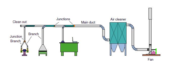
7 Control Ventilation BMPs Min cap vel 400 fpm 250 fpm for most other 150 fpm max for weld HVLV 15k fpm Use hevent for all design fpm for transport velocity 7


8 Example of High Velocity Low Volume Multiple pick ups Close to source Proximity to cutting tool is important Work station is better maintained 8

9 9


10 Don t forget the make up air Ventilation BMPs Polishing filtration HEPA filter inside air Min MERV 14 for outside make up Zone concept for pressures and flow of air Bag in Bag out is standard 10
11 Control: Intervention Verification Purpose: Verify interventions have reduced exposure levels Resample priority tasks and compare with preintervention data set Conduct baseline sampling when satisfied Re-characterize profiles Adjust RP requirements if appropriate 11 11


12 Specific Concerns Powder Handling Metallic Beryllium powder is combustible Open air transfers Contaminated tools 12 12

13 Specific Concerns Machining Operations Metallic beryllium is abrasive System leaks/fire hazard Recycling of lubricant/coolant without a filtration system Particle speed/size Coolant splash Material identification Bubble bursting 13 13


14 Liquid Droplets from Machining of Beryllium 14 14


15 Bubble Bursting Plating & Chemical Cleaning 15


16 Maintenance Activities Leaks, Inspections, Cleaning Process sludge/residue/waste Coolant systems Ventilation systems 16 16


17 Maintenance Activities Tool Care Hand versus power Decontamination and containment Sharpening Dedicated tooling 17 17
18 Exposure Assessment Today we will look at the following SEGs Bench Grinding CNC milling 18

19 Control - Benching Benching consists of handheld grinding and polishing tasks on internal injection mold cavity surfaces. Benching operators use a variety of tools to accomplish their tasks including: hand stones, scotch bright pads, high speed electric sanders, pneumatic grinders, sanders, and lubricants. Wheel surface speeds used are variable and can be as high as 20,000 rpm. 19


20 Exposure evaluation baseline Baseline Exposure Evaluation Seventeen (17) full shift exposure samples were collected in the breathing zone of operators performing Benching on internal injection mold cavity surfaces containing CuBe Alloy 25. Personal Sample Results Number of Samples Range µg/m 3 Percent Exceedance 1 at 0.2 µg/m 3 UTL 2 (95/95) µg/m Percentage of exposures expected to exceed 0.2 µg/m 3. A percent exceedance of < 5% is considered to be Well Controlled. 2Upper Tolerance Limit one can be ninety-five-percent confidence that fewer than 5% of measurements are above the UTL(95/95) 20
21 Controls in use during Baseline Characterization The benching stations in use at the start of this evaluation were equipped with a Dust Kop type dust collection unit. Some of the stations were equipped with a 6 flex duct on top of the benching table that could be positioned by the operator; two of the stations had down draft type tables. All of the Dust Kop ventilation units were powered by on/off switches located at the operator s work stations. The airflow provided by the existing Dust Kop ventilation units ranged from 310 to 777 cfm. 21
22 Exposure Characterization Summary Evaluation Interpretations Airborne exposures to beryllium exceeding the Materion Inc. REG for airborne beryllium of 0.2 µg/m 3 were observed in Benching operations. Additional work practice and engineering controls, such as a redesign of the LEV capabilities, were necessary to improve particulate capture. 22
 Industrial Ventilation Manual, 26th")
23 Exposure Control Improvements Post Intervention Work Station The benching work stations were redesigned using the experience of benching operators, plant management and design criteria recommended by the American Conference of Industrial Hygienists (ACGIH ) Industrial Ventilation Manual, 26th Edition. 23
 Donaldson Torit dust collection system was")
24 Details of the redesigned benching ventilation system are listed below: To accommodate variability in production levels a centralized, variable frequency drive (VFD) Donaldson Torit dust collection system was installed. 24

25 Control at the source Partially enclosing style hoods were installed. These hoods were equipped with improved lighting to allow the operator better visibility, allowing the operator to work farther from the part. Hoods were designed with a top and sides to reduce the effects of cross-drafts created by room air currents. 25
 and eliminates dead zones in the top of the hood.")
26 Control at the source The hood was designed to be a combination of back draft and down draft slot hood. This style hood maximizes laminar air flow, significantly reduces the influence of eddies at the front of the hood (where the pieces are worked) and eliminates dead zones in the top of the hood. The design airflow rate for each hood was in the range 250 cfm per square foot of hood face area. Ductwork transport velocity target equals 4000 fpm. 26

27 Control at the source Each station is activated by a single power switch, turning on lighting, all pneumatic and electrical power, and opening the hood blast gate. Tools are interlocked to the ventilation system and will not operate unless blast gate is open. Removable plates make for easy cleaning of the downdraft hood drop-out plenum. The entire hood tilts to allow better access to the part. Post Intervention Work Station 27
28 Post intervention exposure evaluation Post Intervention Exposure Evaluation Twenty-eight (28) full shift exposure samples were collected in the breathing zone of operators performing Benching on internal injection mold cavity surfaces containing CuBe Alloy 25. Personal Sample Results Number of Samples Range µg/m 3 Percent Exceedance 1 at 0.2 µg/m 3 UTL 2 (95/95) µg/m % Percentage of exposures expected to exceed 0.2 µg/m 3. A percent exceedance of < 5% is considered to be Well Controlled. 2Upper Tolerance Limit one can be ninety-five-percent confidence that fewer than 5% of measurements are above the UTL(95/95) 28
29 Cost Information The upgrades to the local exhaust ventilation included the following: Purchase and installation of 35,000 cfm Donaldson Torit Downflow dust collector, with: Ultralock HEPA After filter return air system Abrasion resistant AR inlet Lined air plenum Bag-In/Bag-Out filter maintainability Tribo Flow particle detection Fabrication and installation of insulated ductwork Fabrication and installation of HEPA filtered recirculation loop. Fabrication of custom hoods 29
30 The bottom line The approximate cost for this installation was $6.25/cfm. Benching Hood dimensions 54 x 30 x24 Open face ft 2 Qhoodt 250 cfm/ft 2 x ft cfm Vslot 5 slots 52 x ft 2 Velocity = 2813 cfm/1.354 ft fpm Benching Vdt 4000 fpm Approximate Cost* $15K * This cost was derived from a project involving the installation of 10 benching hoods and engineering controls for a welding station and abrasive blasting operation. 30
31 Exposure Assessment Today we will look at the following SEGs CNC milling Bench Grinding 31

 controls necessary to maintain exposures to consistently")
32 CNC Milling An airborne beryllium exposure assessment was conducted during CNC Milling of beryllium block or Albemet. The intent of the study was to characterize worker exposure to airborne beryllium and identify work practice and local exhaust ventilation (LEV) controls necessary to maintain exposures to consistently below the Brush Wellman Inc. Recommended Exposure Guideline (REG). Okuma Multus B-300 Makino S56 32

33 CNC Milling/Machining Center CNC Milling involves digitally automated machining of a stationary part mounted onto a fixture. These machining centers allow for a variety of complex milling operations. The water soluble machining fluids are used to lubricate and cool the cut and to flush away the resulting swarf. This containment and flooding of swarf in the enclosed machining centers minimizes the release of particulate. 33

34 Control of the CNC using WSO 34

35 WSO configuration options 35


36 Operating Conditions Disposal Containers and Labeling Designated containers for chip collection and contaminated waste (e.g., shop towels, gloves) were assigned to each AlBeMet machining center. Warning signs were posted on machines, equipment, and containers identifying beryllium containing contents and precautions that need to be taken. 36
37 Exposure Controls for CNC Operation Next Generation 10 Air changes prior to opening doors on mill. Use of redundant systems for exhaust into work area Particle counter with alarm in exhaust plenum DP photohelic with alarm for filter management Interlocks on mill The operator s personal exposure results were reliably below the Materion Brush Inc. REG for airborne beryllium. 37


38 At the Source New facilities will be designed, to the best of our ability, to limit lung exposure and skin contact opportunities, reduce clothing contamination and prevent beryllium migration away from processing areas. 38


39 Control at the design phase Keep beryllium contained. Most cost effective control method in the long run. Effects all of the goals except training and education 39


40 Execution Engineering controls Work practice improvements Job analysis Control plan Performance Auditing 40