Enhanced cyclability of Li O 2 batteries with cathodes of Ir and MnO 2 supported on well-defined TiN arrays
|
|
|
- Brendan Benson
- 5 years ago
- Views:
Transcription
1 Enhanced cyclability of Li O 2 batteries with cathodes of Ir and MnO 2 supported on well-defined TiN arrays Limin Leng, ab Jing Li, a Xiaoyuan Zeng, a Xinlong Tian, a Huiyu Song, a Zhimin Cui,* a Ting Shu, a Haishui Wang, a Jianwei Ren c and Shijun Liao* a Author affiliations * Corresponding authors a The Key Laboratory of Fuel Cell Technology of Guangdong Province, School of Chemistry and Chemical Engineering, South China University of Technology, Guangzhou , China cuizm26@gmail.com, chsjliao@scut.edu.cn Fax: b Sunwoda Electronic Co., Ltd, Shenzhen, China c HySA Infrastructure Centre of Competence, Materials Science and Manufacturing, Council for Scientific and Industrial Research (CSIR), PO Box 395, Pretoria 0001, South Africa Abstract The cycling stability of Li O 2 batteries has been impeded by the lack of highefficiency, and durable oxygen cathodes for the oxygen-reduction reaction (ORR) and the oxygen-evolution reaction (OER). Herein we report a novel TiN nanorod arraybased cathode, which was firstly prepared by growing a TiN nanorod array on carbon paper (CP), and then followed by depositing MnO 2 ultrathin sheets or Ir nanoparticles on the TiN nanorods to form well-ordered, three-dimensional (3D), and free-standing structured cathodes: TiN@MnO 2 and TiN@Ir. Both cathodes exhibited good specific capacity and excellent cycling stability. Their specific discharge capacities were up to 2637 and 2530 ma h g 1, respectively. After 200 cycles for 2000 h at a current density of 100 ma g 1, no obvious decays were observed for TiN@MnO 2 and TiN@Ir cathodes, while significant decreases were observed after the 80 th and 30 th cycles for the Pt/C and cathodes, respectively. Such high performance can be ascribed to the 3D array structure with enough microspace and high surface area, which facilitated the high dispersion of active components and prevented the formation of large/irreversible Li 2 O 2.
2
3 Electronic Supplementary Material (ESI) for Nanoscale. This journal is The Royal Society of Chemistry 2018 Supporting Information Enhanced cyclability of Li-O 2 battery with cathodes of Ir and MnO 2 supported on well defined TiN array Limin Leng a,b, Jing Li a, Xiaoyuan Zeng a, Xinlong Tian a, Huiyu Song a, Zhiming Cui a,, Ting Shu a, Haishui Wang a, Jianwei Ren c, Shijun Liao a, a The Key Laboratory of Fuel Cell Technology of Guangdong Province, School of Chemistry and Chemical Engineering, South China University of Technology, Guangzhou , China. b Sunwoda Electronic Co., Ltd, Shenzhen, Guangdong , China c HySA Infrastructure Centre of Competence, Materials Science and Manufacturing, Council for Scientific and Industrial Research (CSIR). PO Box 395, Pretoria 0001, South Africa. Corresponding author Fax: Corresponding author Fax: address: chsjliao@scut.edu.cn address: cuizm26@gmail.com 1

4 Fig. S1 SEM image of the sample after seed layer is generated on the carbon paper. 2
 (d) Fig.")

 TiO 2 ;")
 TiO 2")
 TiN")


5 (a) (b) 2μm (c) (d) Fig. S2 SEM and magnified SEM images of (a, b) TiO 2 ; TEM images of (c) TiO 2 nanorod, and (d) TiN nanorod catalysts (the insets are the SAED pattern and HR- TEM images). 3
6 Intensity (a.u.) TiO 2 PDF# TiN PDF# TiO 2 TiO 2 powder Carbon fiber paper (CP) θ/degree Fig. S3 XRD patterns of the as-prepared various cathodes. 4
7 Intensity (a.u.) (a) 2 Mn 2p Ir 4p Ti 2s O 1s N 1s Ir 4d Ir 4f Intensity (a.u.) (b) Ti-N Ti-N-O Ti-O Ti-O Ti-N-O Ti-N Ti 2p TiN TiO 2 Ti 2p C 1s TiO Binding Energy (ev) (c) N 1s (d) Binding Energy (ev) Mn 2p 3/ ev Mn 2p Intensity (a.u.) Ti-N Ti-N-O Intensity (a.u.) Mn 3+ Mn 4+ Mn Mn Mn 2p 1/2 Mn 4+ Mn 5+ Intensity (a.u.) (e) Binding Energy (ev) Ti-O Mn-O-Mn O 1s Mn-O-H Ti-O-N H-O-H Intensity (a.u.) Binding Energy (ev) (f) Ir 4f Ir 4f 7/2 Ir 4f5/2 Ir (0) Ir (0) Ir (Ⅳ) Ir (Ⅳ) Binding Energy (ev) Binding Energy (ev) Fig. S4 XPS spectrum of (a) the as-prepared electrodes and b) Ti 2p, (c) N1s, (d) Mn 2p, (e) O 1s and (f) Ir 4f. The XPS survey spectra of cathode exhibits the N 1s peak with a bond energy around 396 ev (Figure S3c), confirming the N substituting O atom in the crystal lattice and formation of the Ti N. Multiple peaks are evolved at lower binding energies in the Ti 2p spectra as depicted in Fig. S3b, which can be assigned to be Ti N (2p 3/2 = ev and 2p 1/2 = ev), Ti N O (2p 3/2 = ev and 2p 1/2 = ev), and Ti O (2p 3/2 = ev and 2p 1/2 = ev) 1-3. Moreover, N 1s spectrum (Fig. S3c) was analyzed by deconvolution method, the characteristic peaks at binding energies of and ev correspond to Ti N and Ti N O peaks, 5
8 respectively. Fig. S4d and e display the Mn 2p and O1s spectra for the TiN@MnO 2 cathode, respectively. The Mn 2p spectrum presents two main peaks located at and ev, being assigned to Mn 2p 3/2 and Mn 2p 1/2 with a spinenergy separation of 11.8 ev, which are in accordance with the previous reports on MnO 4, 5 2. In the O 1s region, there are three peaks with the binding energies of 529.8, and ev. The sharp peak located at ev is for O element in Mn O Mn oxide, and other two peaks at and ev correspond to O element in hydroxide (Mn O H) and water (H O H) 4, 6. The high resolution XPS spectrum of Ir 4f (Fig. S3f) exhibits dominating Ir (0) 4f 5/2 and Ir (0) 4f 7/2 with fractional Ir (IV) 4f 5/2 and Ir (IV) 4f 7/2 suggesting a certain degree of surface oxidation, which is a common phenomenon among metal nanoparticles. 6
9 35 Percentage (%) Mean size: 2.35 nm Particle size (nm) Fig. S5 The particle size distribution of iridium nanoparticles in TiN@Ir catalyst. 7
 Fig. S6 N 2 adsorption-desorption isotherms of various cathodes.")
10 Adsorbed volume (cm 3 g -1 ) Carbon Paper (CP) TiN@MnO 2 TiN@Ir Relative pressure (P/Po) Fig. S6 N 2 adsorption-desorption isotherms of various cathodes. 8
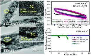
11 Voltage/mV mA g -1 Ar TiN@MnO 2 TiN@Ir Voltage/mV mA g -1 Oxygen Carbon fiber paper Specific capacity (mahg -1 ) (c) 50 Specific Capacity/mA h g Current density (ma g -1 ) TiN@MnO 2 TiN@Ir 400 Specific capacity /mah g Specific Capacity/mA h g ma g Cycle number TiN@MnO 2 TiN@Ir Fig. S7 The discharge-charge curves of the various electrodes at 100 ma g 1 under (a) Ar and (b) O 2 atmosphere; (c) Specific capacities and (d) cycling performance of Li O 2 batteries with various cathodes. 9
12 Voltage /mv ma g -1 1st cycle 2nd cycle 3rd cycle 4th cycle 5th cycle 6th cycle 7th cycle 8th cycle Specific capacity /ma h g -1 Voltage /mv (c) Voltage /mv ma g -1 TiN@MnO st cycle 2nd cycle 3rd cycle th cycle 5th cycle 6th cycle 7th cycle 8th cycle st cycle 2nd cycle 3rd cycle th cycle 5th cycle 6th cycle 7th cycle 8th cycle Specific capacity /ma h g -1 Specific capacity /ma h g ma g -1 TiN@Ir Fig. S8 Discharge/charge curves of Li O 2 batteries with (a), (b) TiN@MnO 2 and (c) TiN@Ir cathodes at 50 ma g 1. 10
")
 (e)")
 (h) recharge")
")
")


13 (a) (b) 1 st discharge 1 st recharge Pt/C (c) 1 st discharge 1 st recharge (d) (e) 1 st discharge 1 st recharge (f) TiN@MnO 2 /C (g) (h) 1 st discharge 1 st recharge TiN@Ir Fig. S9 SEM images of (a, b) Pt/C; (c, d) ; (e, f) TiN@MnO 2 and (g, h) TiN@Ir cathodes after the first fully discharged (a, c, e, g) and recharged (b, d, f, h) process at a current density of 100 ma g 1. 11
 Pt/C, (b), (c) TiN@MnO 2 and (d) TiN@Ir at the first fully discharged and recharged.")
14 Fig. S10 Electrochemical impedance spectra (EIS) of Li O 2 batteries with various cathodes (a) Pt/C, (b), (c) TiN@MnO 2 and (d) TiN@Ir at the first fully discharged and recharged. 12
15 Table S1 Values of the fitting parameters evaluated from the equivalent circuit with various cathodes at the first fully discharged/charged. Pt/C Catalytic cathodes 2 State Rss /ohm Rct /ohm CPE-T /μf CPE-P W1-R /ohm W1-T /F W1-P Fresh discharged recharged Fresh discharged recharged Fresh discharged recharged Fresh discharged recharged
16 Voltage/mV Voltage/mV Terminal Voltage/mV g -1 1st cycle 10th cycle 20th cycle 30th cycle 40th cycle 50th cycle Specific Capacity/mA h g g (c) -1 TiN@MnO 2 1st cycle 10th cycle 20th cycle 30th cycle 40th cycle 50th cycle 70th cycle Specific Capacity/mA h g -1 (e) 200 ma g Cycle number TiN@MnO 2 TiN@Ir Pt/C Voltage/mV Voltage/mV Specific capapcity/ mah g g (b) -1 Pt/C 1st cycle 10th cycle 20th cycle 30th cycle 40th cycle 50th cycle 60th cycle Specific Capacity/mA h g -1 g -1 TiN@Ir 1st cycle 10th cycle 30th cycle 50th cycle 70th cycle 100th cycle 120th cycle 140th cycle 200th cycle (f) Specific Capacity/mA h g ma g Cycle number TiN@MnO 2 TiN@Ir Pt/C Fig. S11 The cycling performance of Li O 2 batteries with the (a), (b) Pt/C, (c) TiN@MnO 2 and (d) TiN@Ir electrodes at 200 ma g 1 with a limited capacity of 500 ma h g 1 ; (e) the terminal voltage and (f) capacities of discharge with various cathodes vs. cycle number. 14
 50 th")
 50 th discharge (f) 50")
 50 th")

 ; (e, f)")

 at 100")
17 (a) 50 th discharge (b) 50 th charge Pt/C (c) 50 th discharge (d) 50 th charge (e) 50 th discharge (f) 50 th charge 2 (g) 50 th discharge (h) 50 th charge Fig. S12 SEM images of Li O 2 batteries with the (a, b) Pt/C; (c, d) ; (e, f) TiN@MnO 2 and (g, h) TiN@Ir cathodes after the 50 th discharged (a, c, e, g) and charged (b, d, f, h) at 100 ma g 1 with a fixed capacity of 500 ma h g 1. 15
18 References 1. X. C. a. C. Burda, J. Phys. Chem. B, 2004, 108, J. Z. Ye Cong, Feng Chen and Masakazu Anpo, J. Phys. Chem. C, 2007, 111, B. Avasarala, T. Murray, W. Li and P. Haldar, Journal of Materials Chemistry, 2009, 19, T. B. a. D. B. l. Mathieu Toupin, Chem. Mater., 2004, 16, A. L. Reddy, M. M. Shaijumon, S. R. Gowda and P. M. Ajayan, Nano letters, 2009, 9, M. C. a. M. Ishikawa, Journal of The Electrochemical Society, 2000, 147,