EMSE Weak-Beam Dark-Field Technique
|
|
|
- Antony Mark Booth
- 5 years ago
- Views:
Transcription
1 Weak-Beam Dark-Field Technique 1
 bright-field image shows dark line on bright background drawbacks: contrast not great line of minimum intensity: î true position of dislocation core image appears")
2 Weak-Beam Dark-Field Imaging Basic Idea recall bright-field contrast of dislocations: specimen close to Bragg condition, s î 0 near the dislocation core, some planes curved to s = 0 ) strong Bragg reflection near dislocation core ) bright-field image shows dark line on bright background drawbacks: contrast not great line of minimum intensity: î true position of dislocation core image appears broad and diffuse 2


3 Weak-Beam Dark-Field Imaging of Dislocations Basic Idea 3

4 Weak-Beam Dark-Field Imaging of Dislocations Basic Idea tilt farther away from Bragg condition only regions directly at the dislocation core are still curved enough to fulfill s = 0 line of strongest Bragg reflection true position of dislocation core but: Bragg reflection becomes weak 4
5 Weak-Beam Dark-Field Imaging of Dislocations Basic Idea drawback: Bragg reflection becomes weak but: appears weak only because di raction pattern averages over entire region locally, near the dislocation core, the reflection is strong employ Bragg reflection for dark-field imaging dislocations appear with sharp, well-localized, and strong contrast This is the concept of Weak-Beam Dark-Field Imaging. 5

6 Example: Dislocations in Cu 6
7 Weak-Beam Dark-Field Imaging Adjustment of Di raction Conditions goal: dark-field imaging with weak beam need to adjust considerably large and well-defined excitation error s consider systematic row of reflections: O, g, 2g, 3g,... a large excitation error s of g can be precisely and reproducibly adjusted by setting up exact Bragg condition (s n = 0) for a higher order reflection ng of the systematic row precise adjustment of s n = 0 can be achieved with the help of Kikuchi lines This setup is denoted as g ng di raction condition. 7

8 Weak-Beam Dark-Field Imaging Adjustment of Di raction Conditions 8
9 WBDF: Observation of Dislocation Dissociation Burgers vector b of a dislocation: displacement between region above and below the cut plane complete crystal dislocation: b = h i a i, h i Z line energy of dislocations: E L = Gb 2 4 (1 ) 1 Cos 2 apple c r [#] Ln b G: shear modulus; : Poisson ratio; b: Burgers length; #: dislocation character (angle between b) and local line direction s, c : parameter characterizing the core radius. E L b 2 9
10 WBDF: Observation of Dislocation Dissociation displacements are additive E L b 2 energy can be released by dissociation if b b 1 + b 2 b b2 2 < b2 b 1, b 2 : Burgers vectors of partial dislocations not lattice translations stacking fault inbetween 10
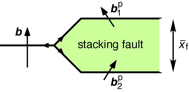
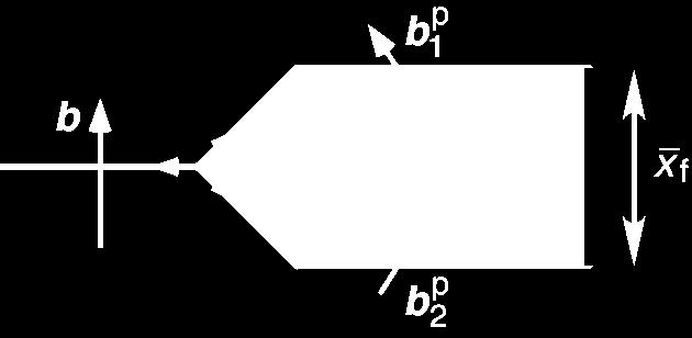
11 WBDF: Observation of Dislocation Dissociation 11
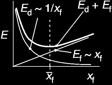
12 WBDF: Observation of Dislocation Dissociation repulsive interaction between partial dislocations: x 1 f attractive interaction due to stacking fault energy f : x f result: equilibrium (minimum total energy) corresponds to finite stacking fault width x f x f = x f [ f ] weak-beam dark-field imaging can determine stacking fault energy f parameter of key importance for mechanical behavior! (temperature dependence of plasticity) 12


13 WBDF: Observation of Dislocation Dissociation Example: Cu 13
14 STEM: Scanning TEM 14

15 Scanning TEM 15
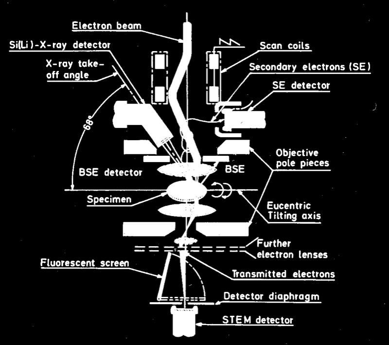
16 STEM Scanning TEM conventional ( still ) of TEM: whole specimen area is illuminated simultaneously STEM: specimen is scanned point-by-point with focused electron probe, similar to scanning electron microscopy but here: transmission, much better resolution! realization: pre-field of objective lens as additional condenser lens small electron probe at the specimen, 1 nm no further lenses are needed below the objective lens! TEM/STEM instruments: further lenses may be excited (e. g. to image di raction pattern through small bores) 16

17 STEM Principle 17

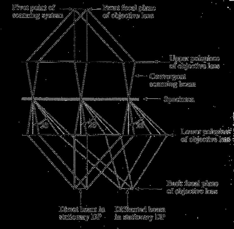
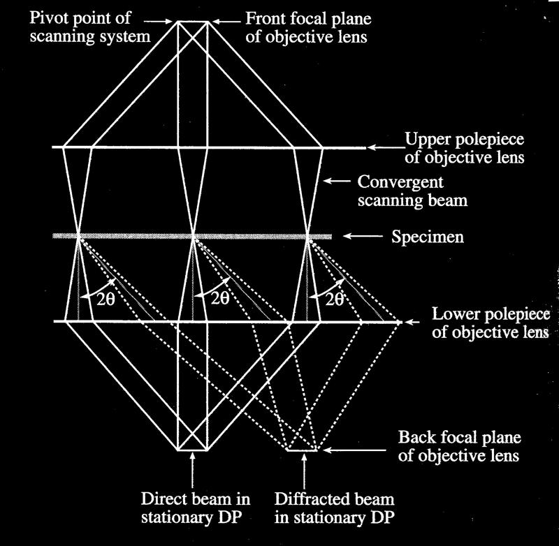
18 Ray Path in STEM Mode 18
19 STEM Scanning TEM saw-tooth voltage generator: acts on deflection coils to scan the beam simultaneously deflects, in synchronism, electron beam of a cathode-ray tube intensity of the CRT beam can be modulated by any signal from the electron specimen interactions bright-field and dark-field mode (select by placing large circular or sector diaphragms in front of detector) detectors: semiconductor or scintillator-photomultiplier detectors see stationary Fraunhofer di raction pattern! 19
20 STEM versus TEM TEM: small illumination aperture i STEM: small electron probe requires large illumination aperture, i 10 mrad detector aperture d has to be matched bright field mode: d i otherwise: noise important options 1. annular detector record forward-scattered electrons with 10 Z contrast (thermal-di use scattering) 20


21 STEM Annular Darkfield Detector 21
22 STEM versus TEM 2. backscattered electron (BSE) detector 3. secondary electrons (SE) detector exit energies of secondary electrons only ev spiral trajectories owing to strong axial magnetic field detection by scintillator-photomultiplier combination image the surface structure of the specimen important advantages of STEM over TEM: avoids chromatic aberration by inelastic scattering in thick specimens STEM with field-emission gun: very high beam currents great for analytical work! 22
23 Diffraction Patterns in STEM Mode 23

24 The Reciprocity Principle 24
25 The Reciprocity Theorem scanning unit between source and objective lens deflects the electron probe in a raster across the specimen projected backwards, the rays scan over a virtual source, which corresponds to the image plane of a TEM in STEM, the CRT is needed to image this virtual plane by modulating the CRT with the detector signal 25


26 STEM versus TEM Examples 26


27 STEM versus TEM Examples 27


28 STEM versus TEM Examples 28