Testing Printed Circuit Boards for Creep Corrosion in Flowers of Sulfur Chamber: Phase 2A
|
|
|
- Joy Bell
- 6 years ago
- Views:
Transcription
1 Testing Printed Circuit Boards for Creep Corrosion in Flowers of Sulfur Chamber: Phase 2A Haley Fu inemi, Shanghai, China Prabjit Singh IBM Corporation, Poughkeepsie, NY, USA Aamir Kazi and Wallace Ables Dell Corporation, Austin, TX, USA Dem Lee and Jeffrey Lee ist-integrated Service Technology, Inc., Taiwan Karlos Guo and Jane Li Lenovo (Beijing) Limited Corporation, Beijing, China Simon Lee and Geoffrey Tong The Dow Chemical Company, Tao Yuan Hsien, Taiwan Abstract The inemi technical subcommittee on creep corrosion is developing a flowers-of-sulfur (FOS) based qualification test for creep corrosion on printed-circuit boards (PCBs). In phase 1 of the project, the performances of FOS chambers of two designs were evaluated by measuring the corrosion rates of copper and silver foils. This paper deals with the phase 2A of the project in which PCBs with immersion silver (ImAg) and lead-free hot-air-surface- level (HASL) finishes soldered with rosin and organic acid fluxes were tested. The test variables were chamber temperature, type of saturated salt solution determining the relative humidity, chamber setup and particulate contamination. The results of test runs conducted at 4 laboratories involved in the round robin testing are very promising. The ImAg PCBs soldered with organic acid flux suffered the most creep corrosion in agreement with the generally agreed to field experience. There were fewer instances of creep corrosion on test PCBs with ImAg finish soldered with rosin flux and on test PCBs with lead-free HASL finish. Creep corrosion was generally associated with plated through holes (PTHs). Contaminating the test PCBs with ammonium salts contributed to more creep corrosion but made the test somewhat less discriminatory in that even test PCBs with HASL finish soldered with rosin flux suffered some creep corrosion. 1. Introduction Creep corrosion on printed circuit boards (PCBs) is the corrosion of copper (and sometimes silver) metallization and the creeping of the corrosion products (mostly sulfide of copper and sometimes silver) on the PCB surfaces. Creep corrosion can be extensive enough to cause the electrical short circuiting of neighboring features on PCBs, such as the plated through holes (PTHs). The history of creep corrosion has been extensively covered in the literature [1-5]. Mixed-flowing gas (MFG) and the flowers of sulfur (FOS) are the two main tests for creep corrosion. The MFG test was developed in the 1980s for the study of electrical connector corrosion [6] and has been applied to the study of creep corrosion [3, 5, 7-9]. The FOS test has been used successfully for the qualification of miniature surface-mount resistors [10] and has recently been shown to produce well defined creep corrosion similar in morphology to that observed in the field [11, 12].


2 (a) (b) Figure 1: FOS chambers setups (a) Paddle wheel FOS chamber with front cover in place; (b) Forced-air FOS chamber setup with front cover removed. The inemi technical subcommittee on creep corrosion is developing a FOS based qualification test for creep corrosion on PCBs. The low cost and the easy of control of the test variables are the main motivation for developing the FOS-based creep corrosion qualification test. Two FOS chambers designed and developed in the phase 1 of the inemi project, described in a recent paper [12] are shown in Figure 1. The sulfur vapors are produced by a bed of sulfur in the bottom of the chamber. At 60 o C the sulfur concentration in the chamber is about 0.6 ppm [13]. Humidity, controlled in the 80-82% range at 60 o C, is provided by saturated salt solutions of KCl or KNO3, The paddle wheel setup rotating at 20 revolutions/minute (RPM) has an air velocity of about 0.1 m/s over the test PCBs. The forced air setup can generate air velocities in the m/s range depending on the blower speed. The performance of the two setups was tested at 60 o C with the chambers loaded with brown epoxy boards, in place of the test PCBs. The brown epoxy boards were chosen purely because of their availability. The temperature and the humidity reached steady state values typically within 2 hours. In the paddle wheel setup at 20 revolutions/minute, the silver corrosion rate was relatively insensitive to humidity at approximately 2000 A/day; whereas, the copper corrosion rate was quite dependent on humidity, increasing from about 3000 to 6000 A/day as the relative humidity was raised from 45 to 96%. In the forced air setup, with air velocity of 1 m/s, the silver and copper corrosion rates had wide scatter with no clear dependence on relative humidity: the silver and copper corrosion rate was in the range and A/day, respectively.
3 (a) (b) Figure 2: (a) Top side; (b) bottom side, the wave soldering side. Figure 3: Copper and silver corrosion rates as a function of PCB loading. The total number of boards, the sum of the brown epoxy boards and the PCBs (green sheets) was 8 in each of the runs. Air velocity had a dramatic effect on the corrosion rates: Copper corrosion rate rose from about 2000 to A/day as the air velocity was raised from zero to 1.3 m/s. Silver corrosion rate was similarly influenced by air velocity, though its corrosion rates were somewhat lower. Phase 1 of the study examined the role ammonium based ionic contamination on creep corrosion. A means was developed to apply controlled concentrations of ammonium based ionic contamination on selected areas of the test PCBs. New circuit boards from a lot that suffered creep corrosion in Asian geographies, high in sulfur- bearing gaseous pollution, were tested in a FOS chamber at 60 o C, 82% relative humidity using KNO3 saturated salt solution, and 1m/s air velocity, with and without the ammonium based ionic contamination. After 3 days of testing the ionically contaminated PCB suffered creep corrosion whereas the non-contaminated PCB did not. This paper describes the phase 2A of the project. The objective of this phase is to optimize the FOS test conditions for PCB creep corrosion qualification. The optimization test runs studied the following variables: Temperature: 50 versus 60 o C; Humidity: KCl versus KNO3 saturated salt solutions; Chamber setup: Paddle wheel versus forced air; Flux: Rosin versus organic acid PCB surface finish: Immersion silver (ImAg) versus Pb-free hot air surface level (HASL); and Ionic contamination: Mixture of (NH4)2SO4, NH4HSO4, NH4NO3 and NH4Cl;
4 2. Experimental procedure and results The flowers of sulfur chamber is a 300-mm cube with a front-loading door sealed with a silicone coated rubber gasket. Humidity was maintained using a saturated salt solution contained in two beakers with 100-mm diameter. Sulfur concentration was maintained by sulfur contained in two beakers with 80-mm diameter or to increase the sulfur bed area, the sulfur was spread over the entire bottom of the chamber. Temperature in the chamber was maintained at 50 or 60 o C with as little temperature fluctuations as possible. There were two approaches for mounting the test specimens in the chamber and for stirring the air: One used a paddle wheel as shown in Figure 1a, with 8 paddles, to mount the 8 test PCBs and move the air; the other was a forced air setup that used a blower to draw the air over 8 stationary test PCBs, as shown in Figure 1b. The paddle wheel had a rotations per minute (RPM) limit of 25. The paddles did not move the air as readily as one s intuition might expect. At the maximum possible RPM, fluid flow simulation estimates the air velocity over the specimens to be about 0.1 m/s. The air velocity over PCBs in computer racks is in the range m/s. To achieve these higher airflow velocities, a new insert was designed and built, as shown in Figure 1b. In this setup, a blower draws air from the front of the setup that has 8 test PCBs. The action of pulling the air up through the setup and having the air take a 180 degrees turn results in quite a uniform air flow across the 8 test PCBs. Air velocities of up to 2 m/s can be achieved. The air velocity is controlled by the speed of the blower which is controlled by the dc voltage input to its electric motor. Figure 4: Copper and silver corrosion rates in the first test run at the four companies. The tests, in round robin fashion, were conducted in 4 laboratories. Three test runs are reported here. The remaining test runs will be reported in a subsequent paper. The test PCBs used in this study, shown in Figure 2, have been described in detail in three earlier papers by the same team [5, 9, 12]. The test boards had either ImAg or Pb-free HASL finishes and were soldered using either rosin or organic acid fluxes. 2.1 First test run: The first FOS tests were run under the following 4 conditions: 1. Company A: KNO3 saturated solution in forced-air FOS chamber (1 m/s) at 60 o C with no ionic contamination; 2. Company B: KNO3 saturated solution in paddle wheel FOS chamber (20 revolutions/minute) at 60 o C with no ionic contamination 3. Company C: KCl saturated solution in paddle wheel FOS chamber (20 revolutions/minute) at 50 o C with no ionic contamination; and 4. Company D: KNO3 saturated solution in paddle wheel FOS chamber (20 revolutions/minute) at 60 o C with ammonium salt ionic contamination.

2SO4, NH4HSO4, NH4NO3 and NH4Cl in 3 concentrations: A1 solution that had 1g total salt content in 1 liter")
5 Table 1: First run in company C. KCI saturated salt solution, 20RPM paddle wheel FOS setup at 50oC with no salt contamination. Figure 5: First test run 20 day results from company C. The ionic contamination was dispensed on the test PCBs from a 10 pipette resulting in drops with 0.1 cm 2 area. The dispensed solution had equal parts of (NH4)2SO4, NH4HSO4, NH4NO3 and NH4Cl in 3 concentrations: A1 solution that had 1g total salt content in 1 liter water resulted in contamination on the test PCB in localized areas; A2 solution that had 0.1 g total salt content in 1 liter water resulted in 10 2 contamination on the test PCB
6 in localized areas; A3 solution that had 0.01 g total salt content in 1 liter water resulted in 1 the test PCB in localized areas. 2 contamination on The surprising observation at the start of the testing, during the first test run, was that when the FOS chambers were loaded with 3 to 6 test PCBs, the copper and silver corrosion rates dropped substantially. In the first test run the sulfur was in two beakers 100 mm in diameter. Figure 3 shows the PCB loading effect on corrosion rates. As the mix of boards in the chamber were changed from all brown epoxy boards to all PCB boards, the copper and silver corrosion rates dropped 4 fold. The reason for this decrease in corrosion rate needs to be studied. The corrosion rate of the chamber fully loaded with 8 test PCBs increases substantially when the sulfur area is increased to cover the base of the chamber. The copper and silver corrosion rates in the first test run at Company C and Company D are shown in Figure 4. The highest corrosion rates were observed by Company A because of 1 m/s air velocity afforded by the forced air setup. Based on field experience and prior mixed flowing gas (MFG) testing, an ideal test should cause more creep corrosion on test PCBs with ImAg finish than on test PCBs with Pb-free HASL finish; and it should cause more creep corrosion on test PCBs soldered with organic acid flux than those soldered with rosin flux. The Company C test results are summarized in Table 1. Only the PCBs with ImAg finish soldered with organic acid flux suffered creep corrosion. The PCBs with ImAg finish soldered with rosin flux and the PCBs with HASL finish suffered with organic acid flux and rosin flux suffered no creep corrosion. The table also shows that the creep corrosion occurred early in the test and did not progress much after 5 days. This observation held true for all subsequent tests. The 20 day test results, both optical and electrical, obtained by Company C are shown in Figure 5. Table 2: 1 st test run in Company D: KNO3, 60oC, paddle wheel, 100 mg/cm2 The first run test results for Company D are shown in Table 2. Only some of the sites contaminated with ammonium salts suffered creep corrosion. All the three PCB types tested suffered creep corrosion. The areas contaminated with 10 2, 1 2 salts and those with no ammonium salt contamination suffered no creep corrosion. The first run test results from the 4 companies are summarized in Table 3. The Company C paddle wheel setup at 50 o C, with KCl saturated salt solution maintaining the relative humidity at 80%, with no salt contamination on the test PCBs, gave results that most agreed with the field and MFG test experience in that only the ImAg PCBs soldered with organic acid flux suffered creep corrosion. The test results of Company A and to a lesser extent Company B were also in agreement with field and MFG experience. In contrast, Company D testing did not result in any creep corrosion in the non-contaminated areas; creep corrosion was localized to areas contaminated with of ammonium salts and occurred on all the three PCB types tested by Company D.
7 Table 3: Summary of the 1st test run at the 4 companies Company Setup Salt Temp Dust ImAg HASL HASL Organic acid flux Rosin Flux Organic acid flux Rosin flux C Paddle Wheel KCL 50 0 No 2.5 HCC 2 LCC B Paddle Wheel KNO No 1 HCC 5 LCC 2 LCC 1 HCC 3 LCC 0 A Forced Air KNO No 3HCC 4LCC 1 HCC 1 LCC D Paddle Wheel KNO Yes 2 HCC 4 LCC 3 HCC 4 LCC 1 HCC 2 LCC No Figure 6: Setup with increased area of sulfur bed used in the 2 nd run. 2.2 Second test run: In the second FOS test runs, the area of the sulfur bed was increased to decrease the PCB loading effect. In some of the company setups, the sulfur bed practically covered the whole base of the FOS chamber, as shown in Figure 6. In others, the diameters of the petri dishes holding the sulfur were increased. Tests were done under the following 4 conditions: Company A: KCl saturated solution in forced-air FOS chamber (1 m/s) at 60 o C with no ionic contamination; Company B: KCl saturated solution in paddle wheel FOS chamber (20 revolutions/minute) at 50 o C with no ionic contamination; Company C: KNO3 saturated solution in paddle wheel FOS chamber (20 revolutions/minute) at 60 o C with no ionic contamination; and Company D: KCl saturated solution in forced-air FOS chamber (1 m/s) at 50 o C with ammonium salt ionic contamination. The copper and silver corrosion rates in the second test run are listed in Figure 7. Table 4 summarizes the results of the second test run. Once again, the Company C results agreed with the field and the MFG test experience: only the PCBs with ImAg finish soldered with organic acid flux suffered creep corrosion


8 Figure 7: Copper and silver corrosion rates in the second test run at the four companies. Figure 8: Company D 2nd test results. The Company D 2 nd test results are shown on Figure 8, which shows creep corrosion on PCBs with ImAg finish soldered with organic acid and rosin flux and no creep corrosion on PCBs with HASL finish soldered with organic acid flux. Company B was the only one that reported creep corrosion on Pb-free HASL PCBs which is not expected based on field and MFG test experience; these failing PCBs were soldered using organic acid flux. The test results of the first and the second run show little difference between the paddle wheel and the forced air setups. There was general team consensus that creep corrosion propensity was higher in chambers with KCl saturated salt solution at 50 o C compared to chambers with KNO3 saturated salt solution at 60 o C. The team settled on running the 3 rd test run at 50 o C and using KCl saturated salt solution. Another reason for selecting the lower chamber temperature of 50 o C was because as a rule it is good practice to have the test conditions as near as possible to the actual field conditions. The KCl saturated salt solution was selected because it has chloride ions in it, though it is well understood that thermodynamics does not allow chlorine to escape from a chloride solution. If it did, the chlorine gas coming off the ocean waters would not allow life on earth as it exists today.


 had 100 concentration and the remaining one third of the area was without any salt contamination.")
9 Table 4: Summary of the 2 nd test run at the 4 companies Company B Company C Company D Figure 9: Copper and silver corrosion rates in the third test run. 2.3 Third test run: As in the earlier two test runs, the test PCBs had ImAg and Pb-free HASL finishes and were soldered using organic acid and rosin fluxes. The four companies conducted the third test runs under identical conditions. All 4 companies used paddle wheel FOS chambers maintained at 50 o C using KCl saturated salt solutions. All the test PCBs were contaminated with ammonium salts. Approximately one third of each PCB area (A2) had localized spots with 10 g/cm 2 total ammonium salt concentration, another one third of the area (A1) had 100 concentration and the remaining one third of the area was without any salt contamination. 2 total ammonium salt The copper and silver corrosion rates in the third test run are listed in Figure 9. The reason for the negative corrosion rate for silver in the Company C FOS chamber may be due to the flaking off of the corrosion product before the post-exposure mass can be measured.


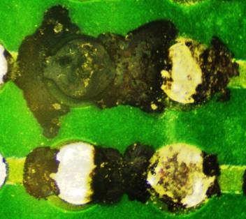
10 Figure 10: Company C 3 rd run. Creep corrosion and resulting electrical shorts. Table 5: Summary of the 3 rd test run at the 4 companies Figure 10 shows creep corrosion and the resulting electrical short circuit on areas of the test boards contaminated with ammonium salts. The results are from the FOS chamber in Company C. The propensity for creep corrosion leading to electrical short circuiting is similar for both organic acid and the rosin flux soldered ImAg finished PCBs. There is only one occurrence of creep corrosion leading to electrical short circuit on the Pb-free HASL finished PCBs. This is in agreement with the field and MFG test experience.
11 Table 5 summarizes the results of the third test run. Test results on contaminated test PCBs are not as discriminating as those on PCBs without contamination. The ImAg finished PCBs suffered more creep corrosion that the HASL finished PCBs. The PCBs soldered with organic acid and those soldered with rosin flux suffered similar extent of creep corrosion. Heavy creep corrosion was found mostly in the areas of total ammonium salt concentration; less creep corrosion was found on 10 2 total ammonium salt concentration and on areas free of contamination. 3. Discussions The motivation to pursue the development of a FOS based creep corrosion qualification test is based on the following factors: Low cost and ease of availability of test equipment. Ease of control of test parameters possible because just the control of temperature in the chamber leads to sulfur concentration and humidity control. The S8 sulfur vapor is in the chemical form that readily attacks the copper and the silver on the PCBs. The point must be emphasized that no other technique can match the relative humidity and sulfur vapor concentration control that a well-designed FOS chamber provides. The sulfur concentrations were not directly measured in this study. Instead, the corrosion rates of copper and silver were measured and used as a measure of the corrosivity of the atmosphere in the chamber. Figures 4, 7 and 9 show the corrosion rates in the three test runs. What may seem to be highly scattered readings are actually quite tightly grouped compared to those from MFG test chambers. One disadvantage of the FOS chamber is that the loading of the chamber with test PCBs decreases the corrosivity of the atmosphere in the chamber as measured by the copper and silver corrosion rates. Increasing the surface area of the sulfur bed increases the copper and silver corrosion rate as shown in Figure 3. The PCBs may be absorbing the sulfur, thus, influencing the copper and silver corrosion rates. A careful study is warranted to more thoroughly characterize the mass transport kinetics in the FOS chamber. Preliminary testing indicates that the test PCBs do not give off enough volatile organic compounds (VOCs) to affect the chemistry of the air in the chamber and thus the copper and silver corrosion rates. 5. Conclusions 6. References In general, the test runs were quite discriminating with the tendency of creep corrosion occurring in the following decreasing order: ImAg-OA > ImAg-R > HASL-OA > HASL-R, where OA refers to soldering using organic acid flux and R refers to soldering using rosin flux. The presence of ammonium salts contamination made the test less discriminatory though the tendency of creep corrosion on ImAg-OA was still greater than that on HASL-R. The sites that suffered creep corrosion were mostly plated through holes: L3, L7, L9 and L13. Of these, L3 and L9 are not solder mask defined (NSMD); whereas, L7 and L13 are solder mask defined (SMD). Creep corrosion occurred with equal frequency at these four sites, though it is expected that there would be more corrosion in the solder mask undercut area for the SMD case leading to higher occurrences of creep corrosion. [1] Schueller R., Creep corrosion of lead-free printed circuit boards in high sulfur environments, SMTA Int l Proceedings, Oct [2] Cullen D. and O Brien G., UL Laboratories, Implementation of immersion silver PCB surface finish in compliance with Underwriters Laboratories, IPC Printed Circuits Expo, [3] Veale R., Rockwell International, Reliability of PCB alternate surface finishes in a harsh industrial environment. SMTA Int l Proceedings, 2005 [4] Mazurkiewicz P., HP Corp., Accelerated corrosion of PCBs due to high levels of reduced sulfur gases in industrial environments, Proceedings of the 32 nd ISTFA, Nov 12-16, 2006, Austin TX. [5] Fu H., C. Chen, P. Singh, J. Zhang, A. Kurella, X. Chen, X. Jiang, J. Burlingame, S. Lee Investigation of factors that influence creep corrosion on printed circuit boards, Pan Pacific Microelectronics Symposium, Kauai, Feb 2012.
12 [6] Abbott W.H., The development and performance characteristics of mixed flowing gas test environment, IEEE Trans. of Component Hybrids and Manufactuirng Technology, vol. 11, no.1. March [7] Xu C., Smetana J., Franey J., Guerra G., Fleming D., Reents W., Willie D., Garcia A., Encinas G., Xiaodong J., Creep corrosion of PWB final finishes: Its cause and prevention, APEX 2009 [8] Zhao P., Pecht, M., Field failure due to creep corrosion on components and palladium pre-plated leadframes, Microelectronics Reliability, 43 (2003) [9] Fu H., C. Chen, P. Singh, J. Zhang, A. Kurella, X. Chen, X. Jiang, J. Burlingame, S. Lee Investigation of factors that influence creep corrosion on printed circuit boards Part 2, SMTAI 2012 [10] Cole, M., L. Hedlund, G. Hutt. T. Kiraly, L. Klein, S. Nickel. P. Singh, T. Tofil, Harsh Enviroment Impact on resistor reliabiity, SMTA Int l Conf. Proc., Oct [11] Kondros P., Private communications, [12] Fu, H., P. Singh, L, Campbell, J, Zhang, W. Ables, D. Lee, J. Lee, J Li, S. Zhang and S. Lee Testing printed circuit boards for creep corrosion in flowers of sulfur chamber, Proc. IPC APEX EXPO [13] Hindin, B., Private communications, 2010.
13 Qualification Test for Creep Corrosion in Flowers of Sulfur Chamber Phase 2 Prabjit Singh IBM Corporation Poughkeepsie NY, USA
14 Phase 2A: Optimization Of Test Procedure Using Copper And Silver Coupons And PCB Test Boards Three formal runs at 4 laboratories. Variables include: Temperature: 50 o C, 60 o C Humidity (saturated salts): KCl, KNO 3 Test chamber: Paddle wheel, forced air setup Flux: Rosin, organic acid Surface finish: ImAg, Pb-free HASL Contamination: NH 4 SO 4, NH 4 HSO 4, NH 4 NO 3 and NH 4 Cl in three concentrations Summary of the 3 test runs Open issues and work in progress.
 2 SO 4 Sodium chloride NaCl 76 76 75 75 75 75")
15 Relative humidities over saturated salt solutions Salt Temperature C Relative Humidity% Potassium sulfate K 2 SO 4 Potassium nitrate KNO 3 Potassium chloride KCl Ammonium sulfate (NH4) 2 SO 4 Sodium chloride NaCl


16 Reference: Battelle
17 - - - P Phase 2A 1st Run
18 Plan for the 1 st run Finish type Flux type Salt Temprature o C Contamination Setup Company Baseline ImAg Pb-free HASL Organic Acid Rosin Flux Rosin Flux KNO3 60 No Forced air 1 m/s A ImAg Organic Acid Baseline Pb-free HASL Rosin Flux Organic Acid KNO 3 60 No Paddle wheel 20 RPM B Organic Acid humidity/ temperature ImAg Pb-free HASL Rosin Flux Organic Acid KCl 50 No Paddle wheel 20 RPM C Contamination ImAg ImAg Pb-free HASL Organic Acid Rosin Flux Organic Acid KNO 3 60 NH4SO4, NH3HSO4, NH4NO3, NH4Cl Paddle wheel 20 RPM D


 L8 L10 L11 L12")
19 The 1 st run: Some observations Corrosion rates on copper and silver foils were lower than expected. Creep corrosion observed to occur somewhat more readily at 50 o C compared with 60 o C. Creep corrosion is quite evident in 5 days. Top side Bottom side (Wave soldering) L8 L10 L11 L12 L13 L5 L9 L14 L7 L6 L1 L4 L2 L15 L3
20 The 15 regions of the PCB test boards L1 SMD linear L2 SMD linear L3 NSMD PTH L4 SMD linear L5 NSMD linear L6 SMD linear L7 SMD PTH L8 NSMD linear L9 NSMD PTH L10 NSMD linear L11 SMD linear L12 SMD linear L13 SMD PTH L14?? L15 NSMD linear
21 Run #1: Copper and silver corrosion Cu corrosion rate, angstroms/day rates A B C D Ag corrosion rate, angstroms/day A B C D Company Company Company Setup Saturated salt Temp %RH Speed PCB/Dummy A Forced air KNO 3 60 o C 1m/s 3/5 B Paddle wheel KNO 3 60 o C 20 PRM 3/5 C Paddle wheel KCl 50 o C 20 RPM 6/2 D Paddle wheel KNO 3 60 o C 20 PRM 3/5
22 Company D: Corrosion rates as a function of PCB loading The solder mask was probably absorbing the sulfur? No evidence of PCBs giving off VOCs. Increasing the area of the sulfur bed increases the Cu and Ag corrosion rates substantially. The total number of PCBs and brown epoxy sheets was kept constant at 8. KNO3, 60 o C, paddle wheel, 20 RPM. Corrosion rate, angstroms/day Silver Copper Number of green sheets 300x300 mm sulfur bed
23 1 st run in Co C: KCl, 50 o C, 20 RPM, paddle wheel, no contamination 1 Days ImAg-OA ImAg-Rosin HASL-OA L1 L2 L3 L4 L5 L6 L7 L8 L9 L10 L11 L12 L13 L14 L15 5 Days Run Board L1 L2 L3 L4 L5 L6 L7 L8 L9 L10 L11 L12 L13 L14 L15 ImAg-OA ImAg-Rosin HASL-OA 15 Days ImAg-OA L1 L2 L3 L4 L5 L6 L7 L8 L9 L10 L11 L12 L13 L14 L15 ImAg-Rosin HASL-OA 20 Days ImAg-OA L1 L2 L3 L4 L5 L6 L7 L8 L9 L10 L11 L12 L13 L14 L15 ImAg-Rosin HASL-OA Heavy creep corrosion Light creep corrosion Corrosion Edge corrosion


24 1 st run in Company C: 20 day test results Edge corrosion readily developed on Pb-free HASL boards Heavy creep corrosion occurred on ImAg boards soldered with organic acid flux. High resistance short in some heavy creep corrosion areas Finish-flux L1 L2 L3 L4 L5 L6 L7 L8 5.03k 2.29k ImAg-OA 81.98k ImAg-rosin HASL-OA 3.94k 35.12k 74.09M L9 L10 L11 L12 L k 11.05k I-O: ImAg, organic acid flux I-R:ImAg, rosin flux H-O: Pb-free HASL, organic acid flux
25 1 st run in Co A: KNO 3, 60 o C, 1m/s, force air, no contamination 1 Day ImAg-OA ImAg-rosin HASL-rosin L1 L2 L3 L4 L5 L6 L7 L8 L9 L10 L11 L12 L13 L14 L15 3 Days ImAg-OA ImAg-rosin HASL-rosin 7 Days ImAg-OA ImAg-rosin HASL-rosin L1 L2 L3 L4 L5 L6 L7 L8 L9 L10 L11 L12 L13 L14 L15 L1 L2 L3 L4 L5 L6 L7 L8 L9 L10 L11 L12 L13 L14 L15 20 Days L1 L2 L3 L4 L5 L6 L7 L8 L9 L10 L11 L12 L13 L14 L15 ImAg-OA ImAg-rosin HASL-rosin Heavy creep corrosion Light creep corrosion Corrosion Edge corrosion
26 Adding contamination Each pattern was divided into quarters. Salt contamination was applied to the quarters, except to area labeled None. The salt solutions contain equal amounts of NH 4 SO 4, NH 4 HSO 4, NH 4 NO 3 and NH 4 Cl. A1 contains 100 µg/cm 2, A2 contains 10 µg/cm 2 and A3 contains 1 µg/cm 2 None A3 A2 A1 L8 L10 L11 L12 L13 L9 None A3 A2 A1 L1 L4 L2 L14 L15 L7 L3


27 How to deposit 10 µg/cm 2 salt on a test board? Volume of drops = 10 µl Area of drop = ν(0.35/2) 2 = cm 2 1 cm 2 to have 10x10-6 g salt cm 2 to have 0.096x10x10-6 g salt 10 µl of solution to have 0.096x10x10-6 g salt 1 liter of solution to have (0.096x10x10-6 )(1/10x10-6 ) g 1 liter of solution to have g salt 1 liter to have 0.96 g salt for 100 µg/cm 2 1 liter to have g salt for 10 µg/cm 2 1 liter to have g salt for 1 µg/cm 2
28 1 st run in Company D: KNO 3, 60 o C, paddle wheel, 100 µg/cm 2 contamination 14 Days ImAg-OA ImAg-rosin HASL-OA L1 L2 L3 L4 L5 L6 L7 L8 L9 L10 L11 L12 L13 L14 L15 21 Days ImAg-OA ImAg-rosin HASL-OA L1 L2 L3 L4 L5 L6 L7 L8 L9 L10 L11 L12 L13 L14 L15 Heavy creep corrosion Light creep corrosion Corrosion Edge corrosion 100 µg/cm 2 deposit on card: Solution A g NH 4 SO g NH 4 HSO g NH 4 NO g NH 4 Cl in 1 liter of DI water The areas with no contamination and with 1 and 10 µg/cm 2 contamination showed almost no creep corrosion.


29 1 st test run in Company D: 21 day results, 100 µg/cm 2 contamination ImAg-OA ImAg-Rosin HASL-OA L3 L3 L3 L7 L7 L7
30 Summary: 1 st run results Company Setup Salt Temp Dust ImAg HASL HASL C B Paddle Wheel Paddle Wheel Organic acid flux KCL 50 o C No 2.5 HCC 2 LCC KNO 3 60 o C No 1 HCC 5 LCC A Forced Air KNO 3 60 o C No 3HCC 4 LCC D Paddle Wheel KNO 3 60 o C Yes 2 HCC 4 LCC Rosin flux Organic acid flux Rosin flux LCC 1 HCC 3 LCC 1HCC 1 LCC 3HCC 4 LCC - 0 I HCC 2 LCC No HCC = heavy creep corrosion; LCC = light creep corrosion
31 Summary: 1 st run results In FOS chambers loaded with PCBs, the solder mask has high absorption rate for sulfur vapors? Increasing the sulfur bed area increased the Cu and Ag corrosion rates substantially. Creep corrosion was associated mostly with the plated through holes. These are locations L3, L7, L9 and L13. Creep corrosion was well developed in 5 days. Additional time saw little increase in creep corrosion. The forced air setup gave more creep corrosion than the paddle wheel setup. 50 o C, KCl sat salt solution (81%RH) with 20 RPM paddle wheel was felt to be the optimum condition for creep corrosion. Company D test run generated creep only in the 100 µg/cm 2 areas.


32 nd
33 Plan for the 2nd run Finish type Flux type Salt Temp o C Contamination Setup Co Baseline ImAg Organic Acid KNO 3 60 No Paddle ImAg Rosin flux wheel 20 RPM Pb-free HASL Organic Acid A Study humidity/ temperature ImAg Organic Acid KCl 50 No Paddle ImAg Rosin flux wheel 20 RPM Pb-free HASL Organic Acid B Study humidity/ temperature ImAg Organic Acid KCl 60 No Forced air ImAg Rosin flux 1 m/s Pb-free HASL Rosin flux C Study contamination ImAg Organic Acid KCl 50 NH 4 SO 4, ImAg Rosin flux NH 3 HSO 4, NH 4 NO 3, NH 4 Cl Pb-free HASL Organic Acid Forced air 20 RPM D
34 Run #2 copper and silver corrosion rates Cu corrosion rate, angstroms/day 10x10 3 8x10 3 6x10 3 4x10 3 2x A B C Company Company Setup Saturated salt D Ag corrosion rate, angstroms/day 12x x10 3 8x10 3 6x10 3 4x10 3 2x A B C Company Speed Temp PCB/Dummy A Forced air KCl 1 m/s 60 o C 6/2 C Paddle wheel KNO 3 20 RPM 60 o C 6/2 D Forced air KCl 1 m/s 50 o C 6/2 B Paddle wheel KCl 20 RPM 50 o C 6/2 D
35 0 Days 2 nd run in Co C: KNO 3, 60 o C, 20 RPM, paddle ImAg-OA ImAg-R HASL-OA wheel, no contamination L1 L2 L3 L4 L5 L6 L7 L8 L9 L10 L11 L12 L13 L14 L15 3 Days ImAg-OA ImAg-R HASL-OA L1 L2 L3 L4 L5 L6 L7 L8 L9 L10 L11 L12 L13 L14 L15 7 Days ImAg-OA ImAg-R HASL-OA 21 Days ImAg-OA ImAg-R HASL-OA L1 L2 L3 L4 L5 L6 L7 L8 L9 L10 L11 L12 L13 L14 L15 L1 L2 L3 L4 L5 L6 L7 L8 L9 L10 L11 L12 L13 L14 L15 Heavy creep corrosion Light creep corrosion Corrosion Edge corrosion
36 2 nd test run Company B: KCl, 50 o C, 20 RPM, paddle wheel, no contamination I day L1 L2 L3 L4 L5 L6 L7 L8 L9 L10 L11 L12 L13 L14 L15 ImAg-OA ImAg-OA ImAg-R ImAg-R HASL-OA HASL-OA 7 days L1 L2 L3 L4 L5 L6 L7 L8 L9 L10 L11 L12 L13 L14 L15 ImAg-OA ImAg-OA ImAg-R ImAg-R HASL-OA HASL-OA 21 days L1 L2 L3 L4 L5 L6 L7 L8 L9 L10 L11 L12 L13 L14 L15 ImAg-OA ImAg-OA ImAg-R ImAg-R HASL-OA HASL-OA Heavy creep corrosion Corrosion Light creep corrosion Edge corrosion


37 2 nd test run in Co B: 20 Days results I-R Card L1 L3 H-O Card L4 I-O Card L9 L13 L3 L9 L1 L3 L8 L4 L13
38 2 nd test run in Company A: KCl, 60 o C, force air at 1m/s, no contamination 1 Day ImAg-OA ImAg-R HASL-R L1 L2 L3 L4 L5 L6 L7 L8 L9 L10 L11 L12 L13 L14 L15 7 Days ImAg-OA ImAg-R HASL-R 14 Days ImAg-OA ImAg-R HASL-R 20 Days L1 L2 L3 L4 L5 L6 L7 L8 L9 L10 L11 L12 L13 L14 L15 L1 L2 L3 L4 L5 L6 L7 L8 L9 L10 L11 L12 L13 L14 L15 L1 L2 L3 L4 L5 L6 L7 L8 L9 L10 L11 L12 L13 L14 L15 ImAg-OA ImAg-R HASL-R Heavy creep corrosion Corrosion Light creep corrosion Edge corrosion No high resistance short detected


39 2 nd test run in Company A: KCl, 60 o C, 1m/s, force air, no contamination, 20 day result I-O Card I-R Card H-R Card L2 L7 L7 L3 L9 L1
40 Adding contamination Each pattern was divided in half. Salt contamination was applied to one half of each pattern. The salt solution contains equal amounts of NH 4 SO 4, NH 4 HSO 4, NH 4 NO 3 and NH 4 Cl. A2 contains 10 µg/cm 2 None A2 L8 L10 L11 L12 L13 L9 L5 None A2 L1 L4 L2 L14 L15 L7 L3 L6
41 2 nd test run in Company D: Forced air setup, 1m/s, KCL, 50 o C, with contamination (creep mainly on 100 µg/cm 2 ) 7 Days ImAg-OA ImAg-R HASL-OA L1 L2 L3 L4 L5 L6 L7 L8 L9 L10 L11 L12 L13 L14 L15 14 Days L1 L2 L3 L4 L5 L6 L7 L8 L9 L10 L11 L12 L13 ImAg-OA ImAg-R HASL-OA 24 Days L1 L2 L3 L4 L5 L6 L7 L8 L9 L10 L11 L12 L13 ImAg-OA ImAg-R HASL-OA Heavy creep corrosion Light creep corrosion Corrosion Edge corrosion


42 2 nd test run in Company D: 24 days results I-O Card L9 I-R Card L9 H-O Card L9 L3 L3 L3
43 Conclusion: 2 nd run of phase 2 Increasing the sulfur bed area increases the Cu and Ag corrosion rates substantially. Setup Salt Temp Dust ImAg HASL C B A D Paddle Wheel Paddle Wheel Forced air Forced air Organic acid flux KNO3 60 o C No 1 HCC 4 LCC KCL 50 o C No 2 HCC 2 LCC KCL 60 o C No 0 HCC 1 LCC KCL 50 o C Yes 0 HCC 2 LCC Rosin flux Organic acid flux Rosin flux HCC 4 LCC 0 HCC 1 LCC 0 HCC 2 LCC 6 HCC 3 LCC HCC 0 LCC No HCC = heavy creep corrosion; LCC = light creep corrosion
44 1 st and 2 nd run summary Run # Site Setup Salt Temp Fine dust ImAg HASL Organic Rosin flux Organic Rosin flux acid flux acid flux 1st run C Paddle KCL 50 o C No 2.5 HCC Wheel 2 LCC B Paddle Wheel KNO3 60 o C No 1 HCC 5 LCC 2 LCC 1 HCC 3 LCC A Forced KNO3 60 o C No 3HCC 1HCC - 0 air 4 LCC 1 LCC D Paddle KNO3 60 o C Yes 2 HCC 3HCC I HCC - Wheel 4 LCC 4 LCC 2 LCC No C C Paddle Wheel B Paddle Wheel A Forced air D Forced air KNO3 60 o C No 1 HCC 4 LCC KCL 50 o C No 2 HCC 1 HCC 6 HCC 2 LCC 4 LCC 3 LCC KCL 60 o C No 0 HCC 0 HCC LCC 1 LCC KCL 50 o C Yes 0 HCC 0 HCC 0 HCC - 2 LCC 2 LCC 0 LCC No
45 1 st and 2 nd run summary (without contamination) Setup Salt Temp Co ImAg HASL Organic acid flux Rosin flux Organic acid flux Rosin flux Paddle KCL 50 o C C 2.5 HCC wheel 2 LCC B 2 HCC 1 HCC 6 HCC - 2 LCC 4 LCC 3 LCC KNO 3 60 o C C 1 HCC LCC B 1 HCC 0HCC 1 HCC - Forced air 5 LCC KCL 60 o C A 0 HCC 1 LCC KNO 3 A 3 HCC 4 LCC 2 LCC 0 HCC 1 LCC 1 HCC 1 LCC 3 LCC In general, the tests runs were discriminating with the frequency of creep corrosion occurrence in the following order: ImAg-OA > ImAg-R > HASL-OA > HASL-R. Company C test runs were the most discriminating with only ImAg-OA creep corrosion.
46 Phase 2 3rd Run
47 Plan for the 3 rd run Each company tested 8 test, two of each type. ImAg Pb-free HASL Organic Acid Rosin Flux Organic Acid Rosin Flux KCL 50 o C A1 and A2 NH4SO4, NH3HSO4, NH4NO3, NH4Cl Paddle wheel To make 100 µg/cm 2 deposit on card: Solution A1: 0.25 g NH 4 SO g NH 4 HSO g NH 4 NO g NH 4 Cl in 1 litre of DI water. To make 10 µg/cm 2 deposit on card: Solution A2. Add 10 ml of solution A1 to 90 ml DI water.

48 Adding contamination Each pattern was divided into 3 sections. Section A1 was contaminated with a total of 100 µg/cm 2 consisting of equal parts of NH 4 SO 4, NH 4 HSO 4, NH 4 NO 3 and NH 4 Cl. A2 contains a total of 10 µg/cm 2 contamination and the 3 rd section was left with no contamination. None A2 A1 L8 L10 L11 L12 L13 L9 L5 L7 None A2 A1 L1 L4 L2 L14 L15 L3 L6


49 Company B Company C Company D Å/day Silver Å/day Copper Å/day Silver Å/day Copper Å/day Silver Å/day Copper Company Setup Saturated salt Temp %RH Speed PCB/Dummy A Paddle wheel KCl 50 o C 20 RPM 8/0 B Paddle wheel KCl 50 o C 20 PRM 8/0 C Paddle wheel KCl 50 o C 20 RPM 8/0 D Paddle wheel KCl 50 o C 20 PRM 8/0

50 3 rd run in Company C: 20 day results 20 Days ImAg-OA 1 ImAg-OA 2 ImAg-R 1 ImAg-R 2 HASL-OA 1 HASL-OA 2 HASL-R 1 HASL-R 2 Salt L1 L2 L3 L4 L5 L6 L7 L8 L9 L10 L11 L12 L13 L14 L15 N N N S N N S N S N S N N S N N S N S S N A1 A2 Non A1 A2 Non A1 A2 Non A1 A2 Non A1 A2 Non A1 A2 Non A1 A2 Non A1 A2 Non Heavy Creep Corrosion Slight Creep Corrosion Pad Corrosion EdgeCorrosion


51 3 rd run in Company C: Opens and shorts after day 20 L7-A1-S L13-A1-S 20 Days Run Board L1 L2 L3 L4 L5 L6 L7 L8 L9 L10 L11 L12 L13 3 rd S-I-O k k 3 rd S-I-O-2 6.7k 3.61k 49.0k rd S-I-R k 6.49k 3.46k 1.65k 3 rd S-I-R k 3.75k 1.70k 3 rd S-H-O-1 3 rd S-H-O-2 3 rd S-H-R-1 3 rd S-H-R k L5-A1 L4-A2 L6-A1-S L9-A1-S L13-A1-S

52 3 rd run in Company B: 20 day results 20 Days ImAg-OA ImAg- Rosin HASL-OA HASL- Rosin A1 A2 None A1 A2 None A1 A2 None A1 A2 None A1 A2 None A1 A2 None A1 A2 None A1 A2 None L1 L2 L3 L4 L5 L6 L7 L8 L9 L10 L11 L12 L13 L14 L15 Heavy creep corrosion Light creep corrosion Corrosion Edge corrosion
53 3 rd run summary: Paddle wheel, KCl and 50 o C Company Fine dust ImAg HASL Organic acid Rosin flux Organic acid Rosin flux flux flux C A1 3.5 HCC 6 LCC 1.5 HCC 9 LCC 0 HCC 4 LCC 0 HCC 4 LCC A2 0 HCC 7.5 LCC 0 HCC 8 LCC 0 HCC 6 LCC 0.5 HCC 2.5 LCC No 0 HCC 4.5 LCC LCC LCC B A1 9 HCC 5 LCC 10.5 HCC 2.5 LCC 6 HCC 2.5 LCC 6.5 HCC 3.5 LCC A2 2 HCC 7.5 LCC 3 HCC 8.5 LCC 3 HCC 4 LCC 3.5 HCC 1.5 LCC No 0 HCC 0.5 LCC 0 1 LCC HCC 1 LCC D A1 3 HCC 5.5 LCC 4 HCC 4.5 LCC 0.5 HCC 3.5 LCC 0.5 HCC 3.5 LCC A No
54 3 rd run summary Heavy creep corrosion are found mostly in the areas with A1 contamination. Less creep corrosion occurred in A2 contaminated areas and in areas free of contamination. Presence of dust reduced the discriminatory nature of the test: The ImAg finished PCBs suffered more creep corrosion than the HASL finished PCBs. The organic acid flux and the rosin flux PCBs suffered similar extent of creep corrosion. Corrosion tends to be developed along the edge of the contamination drops.
55 Overall Conclusions: In general, the tests runs were discriminating with the frequency of creep corrosion occurrence in the following order: ImAg-OA > ImAg-R > HASL-OA > HASL-R. The presence of ammonium salt contamination reduced the discriminatory nature of the test. The sites that suffered creep corrosion were mostly plated through holes: sites L3, L7, L9 and L 13.


56 PCB Design: SolderMask Design (SMD) Undercut Area will induced Creep Corrosion Occurrence due to Copper Exposure Soldermask undercut Creep corrosion 3000 Before FoS test All results in weight ID % C O Mg Si S Cu Sn Ba Spectrum Spectrum Spectrum 3 Spectrum Copper Cavity After FoS test All results in weight% ID C O Al Si S Sn Cu Spectrum Spectrum Spectrum Spectrum Ba Engineering Development Division

57 PCB Design: SolderMask Design (SMD) Corrosion Product grew along Soldermask Undercut Area during FoS test During FoS test All results in weight I % D C O Si S Cu Sn Ba C Spectrum Spectrum Spectrum 3 Spectrum Poor soldermask processing will induce soldermask undercut issue. Copper Pad Soldermask Negative Soldermask Foot (Undercut) Copper Pad Soldermask Normal Soldermask Processing Poor Soldermask Engineering Development Division


58 PCB Design: Non-SolderMask Design (NSMD) Perfect Coverage of Surface Finish can avoid Creep Corrosion Occurrence Before FoS test All results in weight ID % Spectrum 1 Spectrum 2 Spectrum 3 Spectrum 4 C O S Cu Br Sn After FoS test All results in weight% ID C O Si S Ni Cu Br Sn Spectrum 1 Spectrum 2 Spectrum 3 Spectrum Engineering Development Division
59 Work in progress The synergistic effects of chlorine on creep corrosion will be studied using Clorox as the source of chlorine gas. The mechanism of the influence of PCB loading on Cu and Ag corrosion rate will be studied. The FOS test will be verified using test boards from lots that have suffered creep corrosion in the field and from lots that did not suffer creep corrosion in the field.
60 Coauthors Haley Fu, inemi, Shanghai, China Mike Betro and Jing Zhang, IBM Corp, Poughkeepsie, NY, USA Aamir Kazi, Mary Nailos, Dell Corporation, Austin, TX, USA Dem Lee and Jeffrey Lee, ist-integrated Service Technology, Inc., Taiwan Karlos Guo, Jane Li, Lenovo (Beijing) Limited Corporation, Beijing, China Simon Lee, The Dow Chemical Company, Tao Yuan Hsien, Taiwan Intel, Agilent Technologies, CALCE.

61 THANK YOU! QUESTIONS?
ROUND ROBIN TESTING OF CREEP CORROSION DEPENDENCE ON RELATIVE HUMIDITY
 ROUND ROBIN TESTING OF CREEP CORROSION DEPENDENCE ON RELATIVE HUMIDITY Prabjit Singh and Larry Palmer Corporation, Poughkeepsie, New York, USA pjsingh@us.ibm.com Haley Fu International Electronics Manufacturing
HBLED packaging is becoming one of the new, high
 Ag plating in HBLED packaging improves reflectivity and lowers costs JONATHAN HARRIS, President, CMC Laboratories, Inc., Tempe, AZ Various types of Ag plating technology along with the advantages and limitations
PWB Creeping Corrosion Mechanism and Mitigation Strategy
 PWB Creeping Corrosion Mechanism and Mitigation Strategy Jim Kenny, Karl Wengenroth, Ted Antonellis, ShenLiang Sun, Dr. Cai Wang, Edward Kudrak, Dr. Joseph Abys Enthone Inc., Cookson Electronics West Haven,
Characterization, Prevention and Removal of Particulate Matter on Printed Circuit Boards
 As originally published in the IPC APEX EXPO Conference Proceedings. Characterization, Prevention and Removal of Particulate Matter on Printed Circuit Boards Prabjit Singh IBM Corporation Poughkeepsie,
Silver and Sulfur: Case Studies, Physics, and Possible Solutions. C. Hillman, S. Binfield, J. Seppi, and J. Arnold DfR Solutions April 15, 2009
 Silver and Sulfur: Case Studies, Physics, and Possible Solutions C. Hillman, S. Binfield, J. Seppi, and J. Arnold DfR Solutions April 15, 2009 2004-2007 Introduction Silver is a common metal in electronics
A NEW SURFACE FINISH FOR THE ELECTRONICS INDUSTRY Ernest Long PhD and Lenora Toscano MacDermid Waterbury, CT, USA
 A NEW SURFACE FINISH FOR THE ELECTRONICS INDUSTRY Ernest Long PhD and Lenora Toscano MacDermid Waterbury, CT, USA ABSTRACT The performance expectations for printed circuit board surface finishes are greater
Offshore Wind Turbines Power Electronics Design and Reliability Research
 Offshore Wind Turbines Power Electronics Design and Reliability Research F. P. McCluskey CALCE/Dept. Of Mechanical Engineering University of Maryland, College Park, MD (301) 405-0279 mcclupa@umd.edu 1
Assessment of Ni/Pd/Au-Pd and Ni/Pd/Au-Ag Pre-plated Leadframe Packages Subject to Electrochemical Migration and Mixed Flowing Gas Tests
 Assessment of Ni/Pd/Au-Pd and Ni/Pd/Au-Ag Pre-plated Leadframe Packages Subject to Electrochemical Migration and Mixed Flowing Gas Tests Ping Zhao and Michael Pecht CALCE Electronic Products and Systems
100% ROSE Testing The Next Step in High Reliability Electronic Assembly Cleaning Control
 1/10/17 100% ROSE Testing The Next Step in High Reliability Electronic Assembly Cleaning Control By Steve Stach, Chief Technical Writer For the last fifty years, assessment of circuit cleanliness on manufacturing
Particulate and Gaseous Contamination Guidelines for Data Centers 1
 2009, American Society of Heating, Refrigerating and Air-Conditioning Engineers, Inc. (www.ashrae.org). For personal use only. Additional reproduction, distribution, or transmission in either print or
ADVANCED AP PLACEMENT CHEMISTRY. Activity Series. Introduction. Objective. Chemicals and Equipment
 ADVANCED AP PLACEMENT CHEMISTRY Introduction Activity Series An activity series of metals is a table of metals arranged in the order of their decreasing chemical activity or the ease at which the metal
Soldermasks - Processes and Properties
 Soldermasks - Processes and Properties Soldermask what is it for Enable mass soldering techniques Prevent solder shorts under components Prevent corrosion to underlying circuitry Plating resist for surface
Corrosion in electronics: Overview of failures and countermeasures
 Downloaded from orbit.dtu.dk on: Apr 06, 2018 Corrosion in electronics: Overview of failures and countermeasures Jellesen, Morten Stendahl; Verdingovas, Vadimas; Gudla, Helene Virginie Conseil; Piotrowska,
RF Transformer (Stabilized Matching Device) SMST18 series
 SMST18 series") 1 Features RF Transformer Stabilized Matching Device is RF impedance matching component. You can adjust impedance matching easily between antenna and feeding point, when you use RF Transformer. RF Transformer
1 Features RF Transformer Stabilized Matching Device is RF impedance matching component. You can adjust impedance matching easily between antenna and feeding point, when you use RF Transformer. RF Transformer
MATERIAL NEEDS AND RELIABILITY CHALLENGES IN AUTOMOTIVE PACKAGING UNDER HARSH CONDITIONS
 MATERIAL NEEDS AND RELIABILITY CHALLENGES IN AUTOMOTIVE PACKAGING UNDER HARSH CONDITIONS Varughese Mathew NXP Semiconductors 6501 William Cannon Drive, Austin TX, USA Automotive Innovation Driven by Electronics
Topview 5630 Red SMD LED
 Topview 5630 Red SMD LED 1. Features - Chip High-Luminosity SMD LED - 5.6 x 3.0 x 0.9 mm (L x W x H), 4-Pin, Small Size Surface Mount Type - Wide Viewing Angle - Long Operating Life - MSL 3 2. Applications
!"#$#%&#'(() ) **+,-./01)2-,-.3)456,1) /0! **)
 ) **+,-./01)2-,-.3)456,1) /0! **)") !"#$#%&#'(() ) **+,-./01)2-,-.3)456,1) /0!7.5853-09**) Etching Removal of unwanted or non-circuit copper from board Etch resists organic and metallic resists photoresist tin, gold, nickel, silver and alloys
!"#$#%&#'(() ) **+,-./01)2-,-.3)456,1) /0!7.5853-09**) Etching Removal of unwanted or non-circuit copper from board Etch resists organic and metallic resists photoresist tin, gold, nickel, silver and alloys
Effects of Solder Reflow Conditions on the Assembly of Electronics Packaging and Printed Circuit Boards
 Effects of Solder Reflow Conditions on the Assembly of Electronics Packaging and Printed Circuit Boards Gregory K. Arslanian, Minfa Lin, Amy Wressell, Tom Mebrahtu, Victor Wang Air Products and Chemicals
Reference Only. Spec. No. JENF243D-0006K-01 P 1/ 8
 Spec. No. JENF243D-0006K-01 P 1/ 8 Chip EMIFIL LC Combined Monolithic NFL21SP X1C Reference Specification 1. Scope This reference specification applies to Chip EMIFIL LC Combined Monolithic Type NFL21S
Cleaning Before Coating. Presented by Jigar Patel, Senior Process Engineer
 Cleaning Before Coating Presented by Jigar Patel, Senior Process Engineer Cleaning Before Coating Influencing factors Failure mechanisms Coating failures Cleaning before coating Analytics and test methods
contaminated, or if the location of the assembly house is well above sea level.
 VAPOR PHASE REFLOW S EFFECT ON SOLDER PASTE RESIDUE SURFACE INSULATION RESISTANCE Karen Tellefsen. Mitch Holtzer, Corne Hoppenbrouwers Alpha Assembly Solutions South Plainfield, NJ, USA Roald Gontrum SmartTech
No-Clean Flux Activity under Low Standoff Components
 No-Clean Flux Activity under Low Standoff Components Bruno Tolla, Ph.D, Jennifer Allen, Kyle Loomis, Denis Jean ~ KESTER Corporation Mike Bixenman, DBA ~ KYZEN Corporation Electronic Devices More complex
Case Study Power Electronics Cleaning - Solvent to ph Neutral: Enhancing Safety, Process Efficiency and Productivity
 Case Study Power Electronics Cleaning - Solvent to ph Neutral: Enhancing Safety, Process Efficiency and Productivity Ravi Parthasarathy, M.S.Ch.E. Senior Application Engineer ZESTRON Americas Outline Introduction
Effects of SAC Alloy Copper Dissolution Rates on PTH Processes: Cost and performance justify use of certain alternatives to SAC305/405
 Effects of SAC Alloy Copper Dissolution Rates on PTH Processes: Cost and performance justify use of certain alternatives to SAC305/405 1 Craig Hamilton, Polina Snugovsky (Celestica) & Matthew Kelly (IBM)
THIN IMMERSION TIN USING ORGANIC METALS
 THIN IMMERSION TIN USING ORGANIC METALS Jim Kenny, Nils Arendt, Bernhard Wessling, and Karl Wengenroth Enthone Inc., A Business of Cookson Electronics West Haven, CT, USA ABSTRACT With the international
Printed circuit board surface finish and effects of chloride contamination, electric field, and humidity on corrosion reliability
 Printed circuit board surface finish and effects of chloride contamination, electric field, and humidity on corrosion reliability Morten S. Jellesen, Bjørn Duus Mikkelsen, Rajan Ambat Materials and Surface
Reference Only. 2.Part Numbering (ex) NF Z 5B BW 2R9 L N 1 0 L
 NF Z 5B BW 2R9 L N 1 0 L") SpecNo.JENF243J-0011A-01 P1/10 CHIP NOISE FILTER NFZ5BBW LN10 REFERENCE SPECIFICATION 1.Scope This reference specification applies to NFZ5BBW_LN10L Series, Chip Noise Filter. 2.Part Numbering (ex) NF Z
SpecNo.JENF243J-0011A-01 P1/10 CHIP NOISE FILTER NFZ5BBW LN10 REFERENCE SPECIFICATION 1.Scope This reference specification applies to NFZ5BBW_LN10L Series, Chip Noise Filter. 2.Part Numbering (ex) NF Z
Electricity and Chemistry
 Electricity and Chemistry Electrochemistry: It is a branch of chemistry that deals with the reactions involving the conversion of chemical energy into electrical energy and vice-versa. Electrochemical
Product Specification JUL 14 Rev. A1
 Industrial SCSI Connector 1. Scope 1.1 Contents This specification covers the requirements for product performance, test methods and quality assurance provisions of SCSI Connector. 2. Applicable Documents
Becoming Lead Free. Automotive Electronics. Antonio Aires Soldering Technical Specialist Visteon Corporation - Palmela Plant
 Automotive Electronics Becoming Lead Free Antonio Aires Soldering Technical Specialist Visteon Corporation - Palmela Plant 1 Agenda 1. Leadfree Electronics Drivers 2. Requirements 3. Areas of Impact 4.
PARTIALLY-ACTIVATED FLUX RESIDUE INFLUENCE ON SURFACE INSULATION RESISTANCE OF ELECTRONIC ASSEMBLY
 As originally published in the SMTA Proceedings. PARTIALLY-ACTIVATED FLUX RESIDUE INFLUENCE ON SURFACE INSULATION RESISTANCE OF ELECTRONIC ASSEMBLY Xiang Wei, Ph.D., Kyle Loomis, Jennifer Allen, Bruno
Qualification and Performance Specification for Flexible Printed Boards
 Qualification and Performance Specification for Flexible Printed Boards Developed by the Flexible Circuits Performance Specifications Subcommittee (D-12) of the Flexible Circuits Committee (D-10) of IPC
Sample Preparation for Mitigating Tin Whiskers in alternative Lead-Free Alloys
 As originally published in the IPC APEX EXPO Conference Proceedings. Sample Preparation for Mitigating Tin Whiskers in alternative Lead-Free Alloys Mehran Maalekian Karl Seelig, V.P. Technology Timothy
Evaluation copy. Total Dissolved Solids. Computer INTRODUCTION
 Total Dissolved Solids Computer 12 INTRODUCTION Solids are found in streams in two forms, suspended and dissolved. Suspended solids include silt, stirred-up bottom sediment, decaying plant matter, or sewage-treatment
Reference Only. Spec. No. JENF243E-0003Q-01 P 1 / 8. Chip EMIFIL LC Combined Type for Large Current NFE61PT 1H9 Reference Specification
 Spec. No. JENF243E-0003Q-01 P 1 / 8 Chip EMIFIL LC Combined Type for Large Current NFE61PT 1H9 Reference Specification 1. Scope This reference specification applies to Chip EMIFIL LC Combined Type for
Solutions Unit Exam Name Date Period
 Name Date Period Ms. Roman Page 1 Regents Chemistry 1. Which mixture can be separated by using the equipment shown below? 6. Which ion, when combined with chloride ions, Cl, forms an insoluble substance
3SP_CO_1000 Package
 15x15 CO Sensor 1000 ppm Package 110-102 BENEFITS Small Size with Low Profile (20x20x3.8 mm) Long Life (10 years expected life) Fast Response (< 15 seconds) Robust (passes 5000 ppm overload) Low Power
Nickel Electroplating
 Nickel Electroplating In a galvanic or voltaic electrochemical cell, the spontaneous reaction occurs and electrons flow from the anode (oxidation) to the cathode (reduction). In an electrolytic cell, a
Revere Copper Products, Inc.
 Revere Copper Products, Inc. Revere FreedomGray T-Z Alloy Coated Copper Questions & Answers Since introducing FreedomGray, Revere has been asked many questions regarding its nature and use. Following,
PCB Production Process HOW TO PRODUCE A PRINTED CIRCUIT BOARD
 NCAB Group Seminars PCB Production Process HOW TO PRODUCE A PRINTED CIRCUIT BOARD NCAB GROUP PCB Production Process Introduction to Multilayer PCBs 2 Introduction to multilayer PCB s What is a multilayer
Source Apportionment of PM 2.5 at Three Urban Sites Along Utah s Wasatch Front
 Source Apportionment of PM 2.5 at Three Urban Sites Along Utah s Wasatch Front Robert Kotchenruther, Ph.D. EPA Region 10 October 6, 2011 Motivation for this analysis: Utah and Idaho share a PM2.5 nonattainment
Reference Only. Spec. No. JENF243E-0002Q-01 P1 / 8
 Spec. No. JENF243E-0002Q-01 P1 / 8 Chip EMIFIL LC Combined Type for Large Current NFE31PT 1E9 Reference Specification 1. Scope This reference specification applies to Chip EMIFIL LC Combined Type for Large
NCAB Group PCB Specification
 NCAB Group Seminar no. 9 NCAB Group PCB Specification NCAB GROUP NCAB Group PCB Specification 14 key features for durable and reliable PCB s NCAB GROUP NCAB Group PCB Specification 2 Are all PCB s created
SN100C Technical Guide
 SN100C Technical Guide INTRODUCTION SN100C is a lead-free tin/copper//germanium alloy. It has been in use since about the year 2000. Since then SN100C has become a world leading alloy in wave and selective
Chemistry 145 Exam number 4 name 11/19/98 # Faraday s constant is 96,500 c/mole of electrons.
 Chemistry 145 Exam number 4 name 11/19/98 # Faraday s constant is 96,500 c/mole of electrons. A.(16) An electrochemical cell is prepared with a strip of manganese metal dipping in to a 1.0 M MnSO 4 solution
Tin Whiskers Remain A Concern
 Tin Whiskers Remain A Concern Michael Osterman, Research Scientist, Center for Advanced Life Cycle Engineering, University of Maryland The elimination of lead in electronic equipment due to governmental
PROTECTION OF CORROSION-SENSITIVE ARTIFACTS. J.P. Franey, G. Derkits, and D. Fleming Alcatel-Lucent Murray Hill, NJ, 07974, USA ABSTRACT
 ROTECTION OF CORROSION-SENSITIVE ARTIFACTS J.. Franey, G. Derkits, and D. Fleming Alcatel-Lucent Murray Hill, NJ, 07974, SA ABSTRACT rotection and preservation of corrosion-sensitive materials is a critical
an ISO9001 company TECHNICAL INFORMATION FOR TGS2600 Technical Information for Air Quality Control Sensors
 Technical Information for Air Quality Control Sensors an ISO900 company The Figaro 2600 series is a new type thick film metal oxide semiconductor, screen printed gas sensor which offers miniaturization
METAL FINISHING. (As per revised VTU syllabus: )
") METAL FINISHING (As per revised VTU syllabus: 2015-16) Definition: It is a process in which a specimen metal (article) is coated with another metal or a polymer in order to modify the surface properties
METAL FINISHING (As per revised VTU syllabus: 2015-16) Definition: It is a process in which a specimen metal (article) is coated with another metal or a polymer in order to modify the surface properties
Characterizing the Lead-Free Impact on PCB Pad Craters
 Characterizing the Lead-Free Impact on PCB Pad Craters Brian Roggeman and Wayne Jones Advanced Process Lab Universal Instruments Corp. Binghamton, NY 13902 Abstract Pad cratering in Printed Circuit Boards
INTRODUCTION TO ELECTROCHEMISTRY: CURRENT, VOLTAGE, & BATTERIES. Introduction. Electrochemistry Revised 4/28/14
 INTRODUCTION TO ELECTROCHEMISTRY: CURRENT, VOLTAGE, & BATTERIES Introduction Electrochemical Cells In this part of the experiment, four half cells are created by immersing metal strips of zinc, copper,
Major Air Pollutants
 Major Air Pollutants 1 Particulate Matter Particulate refers to all substances that are not gases. It can be suspended droplets / solid particles / mixture of two. Size: 100 µm to 0.1 µm and less. Particulates
IMPACT OF MICROVIA-IN-PAD DESIGN ON VOID FORMATION
 IMPACT OF MICROVIA-IN-PAD DESIGN ON VOID FORMATION Frank Grano, Felix Bruno Huntsville, AL Dana Korf, Eamon O Keeffe San Jose, CA Cheryl Kelley Salem, NH Joint Paper by Sanmina-SCI Corporation EMS, GTS
Technical Data Sheet. Physical Specifications
 Cu/ETCH ME-40A A General Purpose Copper Micro-Etch Product Description Cu/ETCH ME-40 (ME-40) is a two component liquid, designed to provide optimum micro-roughening and cleaning of copper surfaces prior
Impact of Intermetallic Growth on the Mechanical Strength of Pb-Free BGA Assemblies
 Impact of Intermetallic Growth on the Mechanical Strength of Pb-Free BGA Assemblies Patrick Roubaud, Grace Ng, Greg Henshall Hewlett Packard Ronald Bulwith, Robert Herber - Alpha Metals Swaminath Prasad,
Component Palladium Lead Finish - Specification Approved by Executive Board 1997-xx-xx August 22 Version
 Component Palladium Lead Finish - Specification Approved by Executive Board 1997-xx-xx August 22 Version Appendices 1. User Commitment Form 2. Supplier Compliance Form Table of contents 1. Background 2.
2.3 Chemical Changes corrosion Kinds of Corrosion
 2.3 Chemical Changes Have you ever wondered why metal car bodies rust but plastic bumpers do not? As you know, different substances have different physical properties, such as colour and hardness, and
An Overview of IPC Plating Specification Completions, Revisions and Future Plans
 An Overview of IPC Plating Specification Completions, Revisions and Future Plans George Milad Uyemura International Corporation IMAPS New England Section 42nd Annual Symposium Technical Sessions May 5,
China RoHS: How the Changing Regulatory Landscape is Affecting Process Equipment Reliability
 China RoHS: How the Changing Regulatory Landscape is Affecting Process Equipment Reliability Chris Muller 1,*, Henry Yu 2 1 Purafil, Inc., 2654 Weaver Way, Doraville, GA 30340 USA 2 Purafil Asia, Room
TWEED RIVER HIGH SCHOOL 2006 PRELIMINARY CHEMISTRY. Unit 2 Metals
 TWEED RIVER HIGH SCHOOL 2006 PRELIMINARY CHEMISTRY Unit 2 Metals Part 2 Metals differ in their reactivity with other chemicals and this influences their uses. Describe observable changes when metals react
GRAVIMETRIC DETERMINATION OF SULFATE IN AN UNKNOWN SOLUTION
 GRAVIMETRIC DETERMINATION OF SULFATE IN AN UNKNOWN SOLUTION AIM The main objective of this experiment is to determine the concentration of sulfate ion in an unknown solution by using gravimetry. INTRODUCTION
Corrosion Resistance of Heat Exchanger Fin Materials to Potassium Hydroxide Sodium Hypochlorite-Based Cleaning Chemicals and Ammonia
 By Jeremy Olberding, Vice President of Sales, Colmac Coil Manufacturing, Inc. Corrosion Resistance of Heat Exchanger Fin Materials to Potassium Hydroxide Sodium Hypochlorite-Based Cleaning Chemicals and
DEVELOPMENT OF LEAD-FREE ALLOYS WITH ULTRA-HIGH THERMO- MECHANICAL RELIABILITY
 As originally published in the SMTA Proceedings. DEVELOPMENT OF LEAD-FREE ALLOYS WITH ULTRA-HIGH THERMO- MECHANICAL RELIABILITY Pritha Choudhury, Ph.D., Morgana Ribas, Ph.D., Ranjit Pandher, Ph.D., Anil
HAVALLOY Z-C ACID CHLORIDE ZINC / COBALT PROCESS
 ACID CHLORIDE ZINC / COBALT PROCESS provides a bright, ductile electro-deposited zinc-cobalt alloy containing from 0.1% to 0.5% cobalt that is evenly distributed at low, mid and high current densities.
EXTREME LONG TERM PRINTED CIRCUIT BOARD SURFACE FINISH SOLDERABILITY ASSESSMENT
 EXTREME LONG TERM PRINTED CIRCUIT BOARD SURFACE FINISH SOLDERABILITY ASSESSMENT Gerard O Brien, Solderability Testing and Solutions Inc., Richmond, KY Dave Hillman, Rockwell Collins, Cedar Rapids, IA INTRODUCTION
Metal Finishing Products and Service META-MATE ZINCATE 40 "A CONCENTRATED LIQUID ZINCATE FORMULATION FOR THE PRETREATMENT OF ALUMINUM AND ITS ALLOYS"
 Metal Chem,inc. Metal Finishing Products and Service 29 Freedom Court Greer, SC 29650 864.877.6175 Fax 864.877.6176 DATA SHEET META-MATE ZINCATE 40 "A CONCENTRATED LIQUID ZINCATE FORMULATION FOR THE PRETREATMENT
STAINLESS STEEL SELECTION FOR FLUE GAS DESULFURIZATION EQUIPMENT
 STAINLESS STEEL SELECTION FOR FLUE GAS DESULFURIZATION EQUIPMENT Gary M. Carinci William A. Pratt Outokumpu Stainless 3209 McKnight East Drive Pittsburgh, Pennsylvania 15237 gcarinci@tmr-inc.com Abstract
c/bach, 2-B Pol. Ind Foinvasa Montcada i Reixac (Barcelona) SPAIN Tel FAX
 SPAIN Tel FAX") 1- What is 2- How does it work? 3- How do we make it? 4- Applications 5- Processing? WHAT IS? Thick aluminium based substrate, cladded in ED copper foil. Designed for an effective thermal dissipation and
1- What is 2- How does it work? 3- How do we make it? 4- Applications 5- Processing? WHAT IS? Thick aluminium based substrate, cladded in ED copper foil. Designed for an effective thermal dissipation and
Soldering Immersion Tin
 Soldering Immersion Tin Rick Nichols and Sandra Heinemann Atotech Deutschland GmbH Berlin, Germany Abstract The stimulating impact of the automotive industry has sharpened focus on immersion tin (i-sn)
Material Selection and Parameter Optimization for Reliable TMV Pop Assembly
 Selection and Parameter Optimization for Reliable TMV Pop Assembly Brian Roggeman, David Vicari Universal Instruments Corp. Binghamton, NY, USA Roggeman@uic.com Martin Anselm, Ph.D. - S09_02.doc Lee Smith,
Investigation of leakage current flow through wooden poles structures on overhead distribution system
 Proceedings of the 7th WSEAS International Conference on Power Systems, Beijing, China, September 15-17, 2007 120 Investigation of leakage current flow through wooden poles structures on overhead distribution
Qualification Report. June, 1994, QTP# Version 1.1 CY7C46X/47X, MINNESOTA FAB MARKETING PART NUMBER DEVICE DESCRIPTION. Cascadable 32K x 9 FIFO
 Qualification Report June, 1994, QTP# 92361 Version 1.1 CY7C46X/47X, MINNESOTA FAB MARKETING PART NUMBER CY7C460 CY7C462 CY7C464 CY7C470 CY7C472 CY7C474 DEVICE DESCRIPTION Cascadable 8K x 9 FIFO Cascadable
Welding Processes. Consumable Electrode. Non-Consumable Electrode. High Energy Beam. Fusion Welding Processes. SMAW Shielded Metal Arc Welding
 Fusion Consumable Electrode SMAW Shielded Metal Arc Welding GMAW Gas Metal Arc Welding SAW Submerged Arc Welding Non-Consumable Electrode GTAW Gas Tungsten Arc Welding PAW Plasma Arc Welding High Energy
TAIYO THP-100DX1 USA-SP (UL Name: THP-100DX)
") TAIYO THP-100DX1 USA-SP (UL Name: THP-100DX) THP-100DX1 USA-SP after copper plating. THP-100DX1 USA-SP in 1 and 5 kg container. Available in a 1 and 5 kg container One-component Thermally Cured Hole Fill
TAIYO THP-100DX1 USA-SP (UL Name: THP-100DX) THP-100DX1 USA-SP after copper plating. THP-100DX1 USA-SP in 1 and 5 kg container. Available in a 1 and 5 kg container One-component Thermally Cured Hole Fill
PV module durability testing under high voltage biased damp heat conditions
 Available online at www.sciencedirect.com Energy Procedia 8 (2011) 6 384 389 1 5 SiliconPV: 17-20 April 2011, Freiburg, Germany PV module durability testing under high voltage biased damp heat conditions
The Morphology Evolution and Voiding of Solder Joints on QFN Central Pads with a Ni/Au Finish
 The Morphology Evolution and Voiding of Solder Joints on QFN Central Pads with a Ni/Au Finish Julie Silk 1, Jianbiao Pan 2, Mike Powers 1 1 Agilent Technologies, 1400 Fountaingrove Parkway, Santa Rosa,
Indoor corrosivity in museums and archives assessment: standards and recommendations
 7th Indoor Air Quality 2006 Meeting (IAQ 2006) Braunschweig, Germany, 15-17 November 2006 Indoor corrosivity in museums and archives assessment: standards and recommendations Mandana Saheb and Michel Dubus,
No-Clean Flux Residue and Underfill Compatibility Effects on Electrical Reliability
 No-Clean Flux Residue and Underfill Compatibility Effects on Electrical Reliability Eric Bastow Indium Corporation Utica, NY No-clean soldering processes dominate the commercial electronics manufacturing
DECOMPOSITION OF HYDRAZINE IN PRESERVED BOILERS 1
 DECOMPOSITION OF HYDRAZINE IN PRESERVED BOILERS 1 P.C.Mayan Kutty and T.S.Thankachan, Research & Development Center, Al Jubail Abdullah Al Ajlan and Ghazzai Al Mutairi, Laboratory Dept., SWCC Al-Jubail
14. Designing with FineLine BGA Packages
 14. Designing with FineLine BGA Packages S51014-1.0 Chapter 14, Designing with FineLine BGA Packages, replaces AN 114: Designing with FineLine BGA Packages. Introduction As programmable logic devices (PLDs)
Special feature. A.Evaluation of special characteristic. Characteristics R23-C601-3(2006.5) 5. Insulation resistance. ISHIKAWA METAL Co.,Ltd.
 5. Insulation resistance. ISHIKAWA METAL Co.,Ltd.") Special feature This is resin flux cored lead free solder made by Sn and Cu, which can solder easily to Al wire coated by urethane or the other materials. The flux consist of high moisture adsorption materials,
Special feature This is resin flux cored lead free solder made by Sn and Cu, which can solder easily to Al wire coated by urethane or the other materials. The flux consist of high moisture adsorption materials,
Lead Free No Clean Solder Paste 4900P Technical Data Sheet 4900P
 Description MG Chemicals has developed a unique flux system designed specifically for high temperature lead free alloys. It provides the fluxing activity levels that promote thermal stability and prevents
Nomenclature. A systematic method of writing chemical formulas and naming compounds
 Nomenclature A systematic method of writing chemical formulas and naming compounds Chemical symbols Symbols are used to represent elements Either one capital letter, or a capital letter with a lower case
No.JEMCP B a)equivalent Circuit 5.Rated value MURATA PART NO. NFM2CC0UH3D NFM2CC02RH3D (3) Nominal Capacitance Capacitance Tolerance
equivalent Circuit 5.Rated value MURATA PART NO. NFM2CC0UH3D NFM2CC02RH3D (3) Nominal Capacitance Capacitance Tolerance") No.JEMCP0-00863B CHIP EMIFIL CHIP 3-TERMINAL CAPACITOR FOR GENERAL NFM2CC Series Reference Sheet.Scope 2.Reference PART No. List 2 3 4 5 6 7 8 3.MURATA Part NO. System (Ex.) This product specification
No.JEMCP0-00863B CHIP EMIFIL CHIP 3-TERMINAL CAPACITOR FOR GENERAL NFM2CC Series Reference Sheet.Scope 2.Reference PART No. List 2 3 4 5 6 7 8 3.MURATA Part NO. System (Ex.) This product specification
Premium Acrylic Conformal Coating 419D Technical Data Sheet 419D-Liquid
 Description Premium Acrylic Conformal Coating Our 419D Premium Acrylic Conformal Coating is an IPC-CC-830B and UL 94-V0 certified, fast drying, xylene and toluene free product that provides an excellent
Plating HIGH ASPECT RATIO PCBs
 Plating HIGH ASPECT RATIO PCBs Achieving proper copper deposition in holes on thicker boards is no easy task, even with reverse pulse plating. Understanding the ins and outs of electrolyte agitation is
Electron Microscopy (EM) Grid
 Grid") Anirban Som 25-01-14 Instrumental technique presentation Electron Microscopy (EM) Grid What I will talk about Some basic topics about EM grid Home-made grid preparation Grid cleaning Carbon coating and
Anirban Som 25-01-14 Instrumental technique presentation Electron Microscopy (EM) Grid What I will talk about Some basic topics about EM grid Home-made grid preparation Grid cleaning Carbon coating and
INFLUENCE OF ELECTRICALLY CONDUCTIVE ADHESIVE AMOUNT ON SHEAR STRENGTH OF GLUED JOINTS ON FLEXIBLE SUBSTRATES
 INFLUENCE OF ELECTRICALLY CONDUCTIVE ADHESIVE AMOUNT ON SHEAR STRENGTH OF GLUED JOINTS ON FLEXIBLE SUBSTRATES ABSTRACT: Martin Hirman and František Steiner Department of Technologies and Measurement Faculty
Locked Cycle Leaching Test and Yellowcake Precipitation
 Locked Cycle Leaching Test and Yellowcake Precipitation In 2013, the Saskatchewan Research Council ( SRC ) in Saskatoon, SK, Canada commenced locked cycle alkaline leach testing on drill core samples from
A Study of Environmental Test Sequences for Electrical Units Jung Ho Yang, Yong Soo Kim
 A Study of Environmental Test Sequences for Electrical Units Jung Ho Yang, Yong Soo Kim Abstract Electrical units are operated by electrical and electronic components. An environmental test sequence is
DSP 798LF (Sn42/Bi58) LEAD FREE WATER SOLUBLE SOLDER PASTE
 LEAD FREE WATER SOLUBLE SOLDER PASTE") LF217. 798LF Rev.A TECHNICAL DATA SHEET TECHNICAL SPECIFICATIONS LF217. 798LF Rev DSP 798LF (Sn42/Bi58) LEAD FREE WATER SOLUBLE SOLDER PASTE CORPORATE HEADQUARTERS USA: 315 Fairbank St. Addison, IL 630-628-8083
LF217. 798LF Rev.A TECHNICAL DATA SHEET TECHNICAL SPECIFICATIONS LF217. 798LF Rev DSP 798LF (Sn42/Bi58) LEAD FREE WATER SOLUBLE SOLDER PASTE CORPORATE HEADQUARTERS USA: 315 Fairbank St. Addison, IL 630-628-8083
SurTec 717 Alkaline Zinc/Nickel Electroplating Process (Electrolyte based on Sodium)
") SurTec 717 Alkaline Zinc/Nickel Electroplating Process (Electrolyte based on Sodium) Properties tolerates higher temperatures superior metal distribution produces Zn/Ni alloy deposits containing 12-15
SurTec 717 Alkaline Zinc/Nickel Electroplating Process (Electrolyte based on Sodium) Properties tolerates higher temperatures superior metal distribution produces Zn/Ni alloy deposits containing 12-15
Reference Only. Marked three digits system.(ex. 270pF 271) 8 Lead Type
 8 Lead Type") Spec No. JENF243F-0018K-01 P1/11 Disc-Type EMIFIL (A miniature three-terminal capacitor) DSS6N 1.Scope This reference specification applies to DSS6N series. 2.Part Numbering (Ex.) DS S 6 N B3 2A 271 Q93
Spec No. JENF243F-0018K-01 P1/11 Disc-Type EMIFIL (A miniature three-terminal capacitor) DSS6N 1.Scope This reference specification applies to DSS6N series. 2.Part Numbering (Ex.) DS S 6 N B3 2A 271 Q93
HASTELLOY ALLOYS: SOLUTIONS TO SEVERE WET FLUE GAS DESULFURIZATION ENVIRONMENTS
 HASTELLOY ALLOYS: SOLUTIONS TO SEVERE WET FLUE GAS DESULFURIZATION ENVIRONMENTS H. J. White Haynes International 1020 West Park A venue Kokomo, Indiana 46904-9013 HASTELLOY ALLOYS: SOLUTIONS TO SEVERE
Reference Only. Spec.No.JENF243A-0034J-01 P1/8
 Spec.No.JENF243A-0034J-01 P1/8 Chip Ferrite Bead BLM03H N1 Reference Specification 1.Scope This reference specification applies to Chip Ferrite Bead BLM03H N Series. 2.Part Numbering (ex.) BL M 03 HG 601
WorkShop Audace. INSA ROUEN 8 juin 2012
 WorkShop Audace INSA ROUEN 8 juin 2012 Global Standards for the Microelectronics Industry JEDEC standards for product level qualification Christian Gautier Content JEDEC overview Environmental reliability
NITEC CRYSTAL 1. Elektrolyt to achieve uniform and non reflective Nickel deposits
 Postfach 169 CH-9545 Wängi TG 25.07.2014 NITEC CRYSTAL 1 Elektrolyt to achieve uniform and non reflective Nickel deposits In contrast to bright nickel, the NITEC CRYSTAL electroplating process produces
Advances in Printing nano Cu and Using Existing Cu Based Manufacturing Processes. Michael J. Carmody Chief Scientist, Intrinsiq Materials
 Advances in Printing nano Cu and Using Existing Cu Based Manufacturing Processes Michael J. Carmody Chief Scientist, Intrinsiq Materials Why Use Copper? Lower Cost than Silver. Print on Numerous Substrates.
Can your unit pass a Particulate Emission Compliance Test?
 Source Emissions Testing and Emissions Specialists Can your unit pass a Particulate Emission Compliance Test? Kevin Crosby The Avogadro Group, LLC California - Oregon - Arizona McIlvaine Hot Topic Hour,