Exploratory Investigation of Failure Mechanisms in Transition Regions between Solid Laminates and X-cor Truss Sandwich
|
|
|
- Philippa Doyle
- 5 years ago
- Views:
Transcription
1 Exploratory Investigation of Failure Mechanisms in Transition Regions between Solid Laminates and X-cor Truss Sandwich Abstract T. Kevin O Brien* Isabelle L. Paris** NASA Langley Research Center Hampton, Virginia U.S.A. Small sub-component specimens consisting of solid laminates at the ends that transition to X-cor truss sandwich in the center, were tested in a combination of three point bending, uni-axial tension, and combined tension and bending. The failure process in the transition region was documented for each loading using digital video and high-resolution cameras. For the 3-point bending tests, most of the deformation occurred in the solid laminate regions on either end of the specimen. Some pin debonding from the skin of the X-cor truss sandwich was observed in the transition region and was accompanied by audible pings throughout the loading. Tension loaded specimens failed in the sandwich skin in the middle of the gage length, accompanied by separation of the sandwich core from the back skin and by delamination between the top skin and bottom skin at the transition region. The pinging associated with pin debonding occurred as the load was increased. However, the frequency of the pinging exceeded any visual observations of pin debonding in the video of the transition region. For specimens tested in combined tension and bending, the greatest amount of pinging occurred during initial application of the axial load. High-resolution images in the transition region indicated that the pinging corresponded to pins debonding and buckling due to the through-thickness Poisson contraction of the specimen. This buckling continued to a much smaller extent as the transverse load was applied. Keywords: Composites, X-cor truss sandwich, failure modes * U.S. Army Research Laboratory, Vehicle Technology Directorate. ** National Research Council. 1
2 Background and Introduction Figure 1 shows X-cor truss sandwich panels. The foam/pin preforms were supplied by Aztex Corporation. Laminates were produced at Sikorsky Aircraft Company in an autoclave under vacuum pressure as a sandwich of prepreg skins with a foam core filled with pultruded carbon pins. The foam stabilizes the pins during the curing process when the pins penetrate the skins to form a truss core. Typical X-cor sandwich panels transition to solid laminate strips to allow for the attachment of mechanical fasteners (fig.1). Preliminary studies at Sikorsky Aircraft Company have shown that replacing honeycomb sandwich laminates with X-cor truss sandwich laminates may reduce the weight of a structural component by 10 to 15% while maintaining about the same compression and shear strength as the baseline component, with and without impact damage [1]. In order to fully understand the capabilities of the X-cor, and to take advantage of this concept in designing more efficient structures, a detailed investigation of failure modes and load transfer is required. In this study, small sub-component specimens, consisting of solid laminates at the ends that transition to X-cor sandwich in the center, were cut from large panels and tested in a combination of three point bending, uni-axial tension, and combined tension and bending. Experimental observation of the failure process in the transition region was documented for each loading. Future work will build on the current investigation by characterizing the pin debonding mechanism from the facesheet. This characterization will be used in analyses to predict static and fatigue failures. Materials and Specimen Preparation Square panels measuring twenty-one inches on each side were cured at 350ºF in an autoclave at Sikorsky Aircraft company using a semi-rigid vacuum bag. The pins in the X-cor truss consisted of T300/ carbon/bismaleimide with 65% fiber volume. Pin properties are shown in table 1. Properties of the Rohacell 31IG polymethacrylimide foam are given in table 2. 2
3 The skin laminates contained two ply drops along the span, the first internal and the second external, as the laminate transitioned from the solid laminate to the core sandwich. The Sandwich skin facesheets consisted of IM7/8552 carbon-epoxy plain weave fabric with a nominal ply thickness of inches and a [(+-45)/(0/90)/(+-45)] orientation. The fabric properties are given in table 3. At the edge of the panel where the core ramps down, six more plies were added (on the flat side only) to have adequate bolt bearing strength. The layup of the solid laminate (skin plus the doubler) was [(+-45)/(0/90)/(+-45)] 4. The total nominal thickness of the solid laminates was 0.09 inches. The doubler plies were added in sets of threes progressing from the ends towards the center of the specimen. There were distinct recesses or depressions at the two locations where the doublers were dropped. Each individual ply drop was staggered from the previous by 0.25 inches. Test specimens cut from the panels were twenty one inches long, with a nominal width of one inch. The nominal thickness of the solid laminate was 0.1 inches and the nominal thickness of the sandwich region was 0.58 inches. Full length specimens were tested under uniaxial tension and three point bending. The remaining specimens were cut in half along the length and were tested in uniaxial tension and combined tension and bending in the Axial Tension and Bending (ATB) load frame described later. The foam in the sandwich region mounted in the upper grip was removed via sand blasting and the sandwich was filled with an epoxy potting material so it could sustain the compressive grip loads. In order to examine the pin response under load in the transition region, the foam was removed via sand blasting. Strain gages were mounted on all the specimens. Solid laminates cut from test specimens were also tested in tension to obtain axial modulus and strength properties. Experimental Setup and Procedure Solid Laminate Tension Tests Four specimens measuring 3.0-inches long by 0.5-inches wide were instrumented with a strain gage in the mid-span and tested in uniaxial tension in a 20-kip hydraulic load frame. Thickness and width were 3
4 measured before the test and load and strain were recorded during the test. Tests were performed in load control at a rate of 500 lbs/min. X-cor sandwich Three-point Bending Tests The span for the full-length 3-point bend tests was 20-inches between the outer load noses, with a distance of 3 inches from the support rollers to the start of the sandwich on either side. Hence, the total span consisted of 14-inches of sandwich, including the transition region, and 6- inches of solid laminate. Ideally, it would have been preferable to have a smaller core section and a smaller overall span for these tests. However, because the panel geometry was fixed, it was not possible to obtain these smaller panels during this exploratory investigation. Tests were performed in stroke control at a rate of 0.5 in/min. Strains were recorded at two locations shown in figure 2. Strain gage #1 was mounted on the tension side of the solid laminate just before the transition to the sandwich. Strain gage #2 was mounted on the tension side skin of the sandwich, directly below the center load point. X-cor sandwich Tension Tests Two tension tests were performed on X-cor sandwich laminates in a 20- kip hydraulic load frame. The first test was performed on the full gage length, with the solid laminate region mounted in the upper and lower grip as shown in figure 3a. The gage length between the grips was 16.4 inches. The sandwich section was 14.0-inches long, and the distance along the solid laminate from the end of the transition region to the grip at each end was 1.2 inches. The solid laminate was mounted in the grips using sand paper and tungsten carbide grit sheet. The test was performed in load control at a rate of 500 lbs/min. Strain was recorded at the four locations shown in figure 3a. The second test was performed on the half specimen gage length, with the sandwich laminate mounted in the upper grip and the solid laminate mounted in lower grip as shown in figure 3b. The gage length between the grips was 5.5 inches. The sandwich section was 4.41-inches long, and the distance along the solid laminate from the end of the transition region to the grip was 1.09 inches. The remainder of the solid laminate was mounted in the bottom grip using sand paper and tungsten carbide grit 4
5 sheet along with a steel block inserted to align the uni-axial load train. The test was also performed in load control at a rate of 500 lbs/min. Strain was recorded at the three locations shown in figure 3b. For both tests, The deformation was documented using video recordings with two separate cameras. One camera focused on the X-cor truss transition region between the sandwich and the solid laminate, and the other captured the entire gage length deformation between the grips. X-cor sandwich Combined Tension and Bending Tests These combined loading tests were performed on the Axial Tension and Bending (ATB) machine at NASA Langley. Figure 4 shows the X-cor truss specimen loaded in the ATB. Figure 5 shows the axial and transverse loading that was applied to these specimens. A digital video camera was used to capture the overall deformation and sequence of final failure. A high-resolution digital camera was used to take close up photos of the pin behavior in the transition region during holds in the loading. The gage length between the upper and lower grip for all three tests was 5.5 inches. The solid laminate and steel block insert were mounted in the lower grip and the epoxy potting filled core section was mounted in the upper grip. The first test was run with 1.22-inches distance from the lower grip to the beginning of the transition region between the solid laminate and the sandwich. The last two tests were run with the transition region at the lower grip, as depicted in figure 4 and 5. The orientation was rotated 180 degrees about the vertical for the last two tests. Strain gage data were collected during each test. Four gages were used in test #1 and two gages were used in tests #2 and #3. Test #1 The first specimen was loaded in three sequences. Sequence 1 consisted of an application of 1,500 lbs. of axial tension, followed by a loading transversely to the right in increments of 0.5-inches to a maximum transverse stroke of +2.0 inches. The transverse loading was then removed. With the 1,500 lbs. of axial load still applied, the specimen was then loaded transversely to the left in increments of 0.5-5
6 inches, to a maximum transverse stroke of -2.0 inches. Some pinging noise was heard during the axial load and transverse loading. Sequence 2 consisted of an application of 2,000 lbs. of axial tension, followed by a loading transversely to the right in increments of 0.5-inches to a maximum transverse stroke of +2.5 inches. The transverse loading was then removed. With the 2,000 lbs. of axial load still applied, the specimen was then loading transversely to the left in increments of 0.5- inches, to a maximum transverse stroke of -2.5 inches. Some pinging noise was heard during the axial load and transverse loading. Sequence 3 consisted of an application of 2,250 lbs. of axial tension, followed by a loading transversely to the right in increments of 0.5-inches to a maximum transverse stroke of +1.5 inches. The specimen failed when the transverse stroke was increased beyond 1.5 inches. Test #2 The second specimen was loaded in two sequences. Sequence 1 consisted of an application of 1,500 lbs. of axial tension, followed by a loading transversely to the right in increments of 0.5-inches to a maximum transverse stroke of +2.0 inches. The transverse loading was then removed. With the 1,500 lbs. of axial load still applied, the specimen was then loading transversely to the left in increments of 0.5- inches, to a maximum transverse stroke of -2.0 inches. Some pinging noise was heard during the axial load and transverse loading. Sequence 2 consisted of an application of 2,000 lbs. of axial tension, followed by a loading transversely to the right in increments of 0.5-inches to a maximum transverse stroke of +2.5 inches. The transverse loading was then removed. Unfortunately, during this process the hydraulics shut off by accident. This unloaded the axial tension load, putting some compression on the specimen. Further compression was accidentally applied when trying to remove the specimen from the machine failing the specimen prematurely. 6
7 Test #3 The third specimen was loaded in three sequences. Sequence 1 consisted of an application of 2,000 lbs. of axial tension, followed by a loading transversely to the right in increments of 0.5-inches to a maximum transverse stroke of +2.5 inches. The transverse loading was then removed. With the 2,000 lbs. of axial load still applied, the specimen was then loading transversely to the left in increments of 0.5- inches, to a maximum transverse stroke of -2.5 inches. Some pinging noise was heard during the axial load and transverse loading. Sequence 2 consisted of an application of 2,250 lbs. of axial tension, followed by a loading transversely to the right in increments of 0.5-inches to a maximum transverse stroke of +2.5 inches. The transverse loading was then removed. With the 2,250 lbs. of axial load still applied, the specimen was then loading transversely to the left in increments of 0.5- inches, to a maximum transverse stroke of -2.5 inches. Some pinging noise was heard during the axial load and transverse loading. Sequence 3 consisted of an application of 2,500 lbs. of axial tension, followed by a loading transversely to the right. The specimen failed before the transverse stroke reached the first increment of 0.5 inches. Test Results Solid Laminate Tension Tests Figure 6 shows a typical tension stress-strain response for the skin laminates. Data obtained from these tests are summarized in table 4. These data were used to anticipate skin failure strains for the following sandwich laminate tests. X-cor sandwich Three-point Bending Tests Figure 7 shows the load versus strain response for the 3-point bending test. Because of the large span of the stiff sandwich region, most of the deformation occurred in the solid laminate regions on either end of the specimen. The test was terminated when the specimen slipped off the 7
8 left-hand roller. At this point, strain gage #1 had reached almost 7,500 µε. However, this was only half the failure strain of the solid laminate as determined by the solid laminate tension tests (fig.6). The deflection in the skin laminate was quite large, and the center load nose stroke was nearly 1.5 inches. Several pings were heard during the loading. These were documented on the digital video taken during the test with a digital video camera. X-cor sandwich Tension Tests Test #1 Figure 8 shows the load versus the strain gage outputs for the full gage length test. The gages were zeroed before clamping in the lower grip, so some gages read small compressive strains at the start of the test. The highest tensile strain throughout the test was indicated by gage #4, located on the back of the sandwich in the middle of the gage length. The video indicated that this is the tension side of the bending in the sandwich region. The video of the full gage length clearly showed the bending induced by the eccentricity of the load path. However, the solid laminate region exhibited bending in the opposite direction, with gage #1 showing more tension strain than gage #3 (fig.8). This was also evident in the video of the local transition region. The first ping indicating pin debonding occurred at 1,250 lbs., with 6,500 µε indicated by gage #4. This pinging continued to occur as the load was increased. However, the frequency of the pinging exceeded any visual observations of pin debonding in the video of the transition region. Final failure was at 2,410 lbs., with close to 12,000 µε indicated by gage #4. This was within the range of failure strains (9,000 µε -15,000 µε) recorded in tension tests on the solid laminates. The specimen failed in the skin near gage #4, accompanied by separation of the sandwich core from the back skin and by delamination between the top skin and bottom skin at the transition region. Test #2 Figure 9 shows load versus the three strain gage outputs for the half gage length test. The load-strain response was similar to the full gage 8
9 length test, except that the maximum strain achieved was slightly higher. The video of the half gage length showed the bending response induced by the eccentricity of the load path. As noted for the full gage length test, Gage #1 mounted on the transition side of the solid laminate indicated more tension strain than gage #2 on the opposite side (fig.9). This was also evident in the video of the local transition region. The first ping indicating pin debonding occurred at 1,150 lbs. of applied load, with 6,360 µε indicated by gage #3. This pinging continued to occur as the load was increased. However, the frequency of the pinging exceeded any visual observations of pin debonding in the video of the transition region. Final failure was at a load of 2630 lbs., with 14,600 µε indicated by gage #3. This was near the top of the range of failure strains (9,000 µε -15,000 µε) recorded in tension tests on the solid laminates. The final failure sequence in the transition region was captured from the last several frames from the video camera (fig.10). Failure appeared to initiate in the tapered skin region, followed by the final failure in the backside of the continuous skin. X-cor sandwich Axial Tension and Bending tests Figure 11 shows the axial load vs. strain gage data for specimen #1 recorded during loading sequence 3. As noted previously in the tension tests that were run to failure, the maximum strain was indicated by gage #3. Gage #4 was added to the ATB test specimens because the previous tension tests, that were run to failure, indicated that the failure might have initiated in the skin at this location. However, the strains recorded in gage #4 were considerably lower than indicated by gage #3. Figure 12 shows the strain versus transverse load response for specimen #1 recorded during loading sequence 3. The axial load was held constant at 2,250 lbs. during the transverse loading. Gages #1 and #2 show the anticipated bending response due to the bending moment generated near the lower grip. However, the strain levels in the skin laminate measured by gages #1 and #2 are considerably lower than that in gage #3. Also, the bending load increases the strain in the core skins at gages #3 and #4, but only by slightly more than the axial loading alone. The highest strain indicated by gage #3 prior to specimen failure was 14,195 µε. 9
10 Figure 13 shows the high-resolution digital images taken during sequence 3 loading. The left image was taken when the specimen was unloaded (P=0). The second image was taken when the maximum axial load was applied (P=2250 lbs). The third image was taken when the transverse stroke was 1.5 inches. The greatest change occurred during application of the axial load. The pinging corresponded to pins debonding and/or buckling due to the through-thickness Poisson contraction of the specimen. This buckling continued to a much smaller extent as the transverse load was applied. It was not evident if this pin buckling could occur in the core regions if the foam was intact. Figure 14 shows the failure sequence in specimen #1, captured by the digital video camera during sequence 3. The middle frame clearly indicated that the failure initiates as a separation of the skin laminates at the transition region between the solid laminate and the X-cor truss. The final frame shows the delamination that grew into the solid laminate as a result of this separation. Once this has occurred the skin laminate fails on the right side. The failure went through gage #3. This may also have been the failure sequence in the previous tension tests run to failure, as opposed to an initial skin failure at the location of gage 4 as previously expected. Test #2 Figure 15a shows the compression deformation on specimen #2 immediately following the loss of hydraulic power, Figure 15b shows the debonding of the skin from the core that occurred following the compression loading that was accidentally applied when trying to remove the specimen from the machine. This accidental failure illustrates the sensitivity of the X-cor sandwich construction to compression where failure may occur without a skin fracture. Unfortunately, there was no record of how much compression was accidentally applied to this specimen. Test #3 Figure 16 shows the axial load vs. strain gage response for specimen #3 recorded during loading sequence 3. As noted previously in the tension tests that were run to failure, the maximum strain was indicated by gage #3. Gage #4 was added to this test because the previous tension tests 10
11 that were run to failure indicated that the failure might have initiated in the skin at this location. However, the strains recorded by gage #4 were considerably lower than indicated by gage #3. Figure 17 shows the strain versus transverse load response for specimen #3 recorded during loading sequence 2. The axial load was held constant at 2,250 lbs. during the transverse loading. The bending load increased the strain in the core skins at gage #3 location. The highest strain obtained indicated by gage #3 during sequence 2 was 14,535 µε. The strain at failure recorded at gage #3 from sequence 3 soon after transverse loading was applied was 15,200 µε. Figure 18 shows the high-resolution digital images of specimen #3 taken during the axial loading in sequence 3. The left image was taken when the specimen was unloaded (P=0). The next four images were taken at increments of axial tension load up to P=2500 lbs. The pinging heard in the video corresponded to pins debonding and/or buckling due to the through-the-thickness Poisson contraction of the specimen. This buckling continued to a much smaller extent as the transverse load was applied. It was not evident if this pin buckling could occur in the core regions if the foam was intact. Figure 19 shows the failure sequence in specimen #3, captured by the digital video camera during the transverse loading in sequence 3. The middle frame clearly indicated that the failure initiates as a fracture in the back core skin near gage #3. The specimen did not separate at the transition region between the solid laminate and the X-cor truss sandwich because the entire skin laminate was in the lower grip. The last frame shows the final failure occurring in the skin laminate on the right side above gage #4. Three separate views of the final failure are shown in figure 20. Discussion and Concluding remarks Small element specimens consisting of solid laminates at the ends that transition to X-cor truss sandwich in the center, were tested in three point bending, uni-axial tension, and combined tension and bending. Experimental observation of the failure process in the transition region was documented for each loading condition using digital video cameras. 11
12 Further documentation was generated for the combined tension and bending loading using a high-resolution camera. For the 3-point bending tests, most of the deformation occurred in the solid laminate regions on either end of the specimen because of the long span for the sandwich region. The test was terminated when the specimen slipped off the left-hand roller when solid laminate strains were only half the failure strain as determined by solid laminate tension tests. Some pin debonding from the skin was observed in the transition region and was accompanied by audible pings throughout the loading. Two tension tests were performed. The first was a full gage length test with solid laminates in the grips. The second was a half-gage length test with a potted core region in the upper grip. For the full gage length test, the first ping indicating pin debonding occurred at 1,250 lbs. and the final failure was at 2,410 lbs. The specimen failed in the sandwich skin in the middle of the gage length, accompanied by separation of the sandwich core from the back skin and by delamination between the top skin and bottom skin at the transition region. For the half gage length test, the first ping indicating pin debonding occurred at 1,150 lbs. and the final failure was at 2,630 lbs. The specimen failed in the sandwich skin in the middle of the gage length, accompanied by separation of the sandwich core from the back skin. For both specimens, the pinging continued to occur as the load was increased. However, the frequency of the pinging exceeded any visual observations of pin debonding in the video of the transition region. Pin buckling was not clearly visible in the digital video images, but probably occurred also, as was indicated by the high resolution camera images during tension loading of the ATB specimens. Three X-cor truss sandwich specimens were tested in combined tension and bending. Two tests were successful, with the third accidentally failing in compression. The greatest change occurred during initial application of the axial load. High-resolution images in the transition region indicated that the pinging corresponded to pins debonding and buckling due to the through-the-thickness Poisson contraction of the specimen. This buckling continued to a much smaller extent as the transverse load was applied. It was not evident if this pin buckling could occur in the core regions if the foam was intact. 12
13 The first specimen had a small portion of solid laminate in the gage length. For this specimen, the failure initiated as a separation of the skin laminates at the transition region between the solid laminate and the X- cor truss, followed by a delamination that grew into the solid laminate. Once this had occurred the skin laminate failed. The second specimen had the entire solid laminate in the grip, which suppressed the delamination. The third specimen failed in compression following the loss of hydraulic power. This caused the skin to debond from the core. This accidental failure illustrated the sensitivity of the X-cor sandwich construction to compression loading where failure may occur without a skin fracture. Future work will build on the current investigation by characterizing the pin debonding mechanism from the facesheet. This characterization will be used in analyses to predict static and fatigue failures. Acknowledgements This study was performed as part of a Cooperative research and Development Agreement (CRDA) between the U.S. Army Research Laboratory, Vehicle Technology Directorate and Sikorsky Aircraft Company, Stratford, Connecticut, U.S.A. References 1) Carstensen, T. Cournoyer, Kunkel, E., Magee, C., "X-Cor Advanced Sandwich Core Material," 33d International SAMPE Technical Conference, Seattle, WA, Nov
14 E 22 = 1.6 x 10 6 Psi (Transverse modulus) ν = 0.28 (Poisson's ratio) Table 1 - X-cor carbon pin properties Density: 1.9 lbs/ft 3 E = 5.12 x 10 3 psi (Axial Modulus) G = 1.85 x 10 3 psi (Shear modulus) X t = 142 psi (Tension strength) X c = 57 psi (Compression strength) S = 57 psi (Shear strength) Table 2 - X-cor foam properties For a 0/90 fabric ply with 0 degrees coinciding with the 1 direction E 11 = 12.2 x 10 6 psi (tension) E 22 = 11.6 x 10 6 psi (tension) E 11 = 10.6 x 10 6 psi (compression) E 22 = 10.6 x 10 6 psi (compression) G 12 = 0.77 x 10 6 psi (shear) ν 12 =0.05 (Poisson's ratio) X t = 155 x 10 3 psi (tension strength in 0 direction) Y t = 138 x 10 3 psi (tension strength in 90 direction) X c = (no data, but greater than the Y c value below) Y c = 123 x 10 3 psi (compression strength in 90 direction) S = 18.1 x 10 3 psi (shear strength) Table 3 - IM7/8552 carbon-epoxy plain weave fabric properties
15 Spec.# Width, in Thickness, in Modulus, Ksi Failure Stress, Ksi Failure Strain, µε * 10,600* * 8,270* , ,000 * grip failures Table 4 - Solid Laminate Test Results
 X-cor")


16 Carbon pins (a) Pultruded carbon pins in foam (b) X-cor truss sandwich (c) Panel with transition from solid laminate to X-cor truss sandwich Fig.1 X-cor Truss Sandwich Material and Panel.
17 Center roller Load, lbs inches 10 inches 100 Left hand roller Gage 1 Gage inch span Stroke, inches Fig. 2. X-cor truss specimen load vs. stroke response under 3-point bend loading.
18 P P Gage #2 Gage #4 Gage #3 Gage #1 Gage #3 Gage #1 Gage #2 P P (a) Full-length specimen. (b) Half-length specimen. Fig.3 X-cor Sandwich Tension Tests

19 Transverse Load cell Axial Load cell Upper grip X-cor specimen Lower grip Fig.4 ATB and X-cor specimen


20 - v Axial load, P + v Fig.5 Details of specimen loading in ATB test machine
21 Stress, Mpa Strain, Fig. 6 Typical tension stress-strain response for solid laminates.

22 500 Gage Gage Load, lbs inches 10 inches 100 Gage 1 Gage inch span Strain Fig.7 X-cor truss specimen load vs. strain response under 3-point bend loading.
23 P 2500 Gage#3 Gage#1 Gage# Gage#2 P, lbs Gage #2 Gage # Gage #1 Gage # Strain, P Fig.8 Load vs. Strain response for full-length X-cor truss sandwich tension test.

24 P Gage#3 Gage#2 Gage# P, lbs Gage #3 500 Gage #1 Gage # Strain, P Fig.9 Load vs. Strain response for half-length X-cor truss sandwich tension test.
")


25 (a) (b) Initial separation (c) (d) Final failure Fig.10 Half-length X-cor truss sandwich tension test specimen failure sequence.

26 2500 Gage Axial Load, lbs Gage Gage 1 Gage 2 Gage 3 Gage 4 Gage 1 Gage Strain, Fig.11 Axial load vs. strain response for ATB X-cor sandwich specimen #1.
27 15000 Gage 3 Gage P = 2,250 lbs. Strain, Gage 1 Gage Gage 4 Gage 2 Gage 1 Gage Transverse Load, V, lbs. Fig.12 Strain vs. transverse load response for ATB X-cor sandwich specimen #1.


28 P = 0 P = 2,250 lbs. v = 1.5 inches Fig.13 Pin buckling in ATB X-cor sandwich specimen #1 subjected to tension and bending.
 Final failure")

29 Delamination (a) Just before failure (b) Separation at transition point (c) Final failure Fig.14 Failure sequence for ATB X-cor truss sandwich specimen #1 loaded in tension and bending, sequence 3.


30 Skin debond (a) Hydraulics shutoff at v = 0.25 in. (b) Compression failure Fig.15 Failure mode for accidentally failed ATB X-cor Sandwich Specimen #2.

31 2500 Gage Axial Load, lbs Gage 3 Gage 4 Gage Strain, Fig.16 Axial load vs. strain response for ATB X-cor sandwich specimen #3.

32 15000 Gage 3 Gage Strain, P = 2,250 lbs Gage 4 Gage Transverse Load, V, lbs. Fig.17 Strain vs. transverse load response for ATB X-cor sandwich specimen #3.

33 P = 0 P = 1,000 lbs. P = 1,500 lbs. P = 2,000 lbs. P = 2,500 lbs. Fig.18 Pin buckling under axial tension in ATB X-cor sandwich specimen #3.
 Initial failure (c)")

34 Gage 3 Delamination Gage 4 (a) Just before failure (b) Initial failure (c) Final failure Fig.19 Failure sequence for ATB X-cor truss sandwich specimen #3.

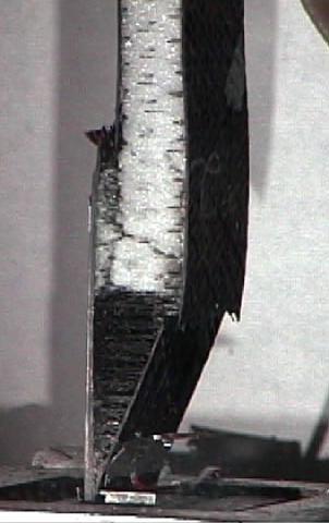

35 Delamination Fig.20 Failed ATB X-cor truss sandwich specimen #3.