Bioreactor Implementation and
|
|
|
- Amelia Lawson
- 5 years ago
- Views:
Transcription
1 Bioreactor Implementation and Design Debra R. Reinhart, PhD, PE Professor and Associate Dean College of Engineering and Computer Science University of Central Florida Orlando, Florida USA
2 Topics Leachate collection and removal system Moisture routing Leachate recirculation Geotechnical stability Gas collection Final cover
3 Essential Needs for a Bioreactor Composite liner Efficient leachate collection system Consider hydrodynamics Geotechnical stable design Leachate recirculation system Adequate storage Active gas collection system Appropriate p final cover system Competent landfill operator
4 Leachate Collection System Waste Sand Drainage and Protective Layer Geotextile Geomembrane Liner Clay Liner Coarse Drainage Material Leachate Collection Pipe
5 Liner System Performance Single composite liner acceptable with downgradient di monitoring i Double liner is outstanding, with less emphasis on groundwater monitoring
6 Leachate Collection Design Major impediment to liquid additions Koerner recommends k min >1.o cm/sec Gravel or geonet/sand composite If gravel used geomembrane must be protected by geotextile Puncture design methods preferred Avoid filter over gravel, use sand over geonet
 may lead to excessive")

7 Leachate Removal Design High normal stresses (deep wet landfills) may lead to excessive deflection Higher liner temperatures Geonet designs avoid pipe altogether Pipe monitoring and maintenance
8 Pipe Maintenance
9 Waste Heterogeneity Impermeable Cover Ponding Water Preferential Channels Gas Flow
10 Purpose of Hydrodynamic Modeling Provide insight i into the design and operation of a leachate recirculating landfill
11 Mathematical Modeling Saturated and Unsaturated Transport Two-dimensional i finite i element/finite i difference simulation model for saturated and unsaturated flow and transport Pertinent inputs are permeability, porosity, unsaturated flow relationships, and fluid fluxes Primary outputs are isoclines of pressure and saturation
12 Model li Inputs Permeability Angle of anisotropy Dispersivities Fluid properties of compressibiity, specific heat, diffusivities Solid matrix properties of compressibility, specific heat, diffusivity, and density
13 Heterogeneous Modeling Results Three Possible Routing Scenarios Waste height, m Waste height, m Waste height, m Saturation n, fractional Horizontal co-ordinate, m Horizontal co-ordinate, m Horizontal co-ordinate, m 0.30 Normal Permeability Distribution, K median =10-3 cm/s
14 Heterogeneous Modeling Results Three Possible Routing Scenarios Waste height, m Waste height, m Waste height, m Saturatio on, fractional Horizontal co-ordinate, m Horizontal co-ordinate, m Horizontal co-ordinate, m 0.30 Normal Permeability Distributions, K median =10-4 cm/s
15 Heterogeneous Modeling Results Three Possible Routing Scenarios Waste height, m Waste height, m Waste height, m Saturation n, fractional Horizontal co-ordinate, m Horizontal co-ordinate, m Horizontal co-ordinate, m 0.30 Exponentially Increasing Permeability Distribution, K median =10-4 cm/s


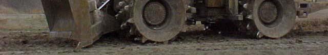
16 Waste Compaction
17 Vertical Permeability =10-4 cm/s eight, m 10 8 eight, m 10 8 eight, m fractional Waste H 6 4 Waste H 6 4 Waste H aturation, f S Horizontal Co-ordinate, m Horizontal Co-ordinate, m Horizontal Co-ordinate, m K V = K H K V < K H K V > K H
18 Cover Issues ste Height, m Was Daily Cover Material te Height, m Wast Daily Cover Material aturation, fractional Horizontal Co-ordinate, m Horizontal Co-ordinate, m 0.45 S Waste Permeability = 10-3 cm/s Daily Cover Permeability = 10-5 cm/s
19 Cover Issues te Height, m Wast Daily Cover Material Horizontal Co-ordinate, m te Height, m Wast Daily Cover Material Horizontal Co-ordinate, m Sa aturation, fr ractional Waste Permeability = 10-3 cm/s Daily Cover Permeability = 10-2 cm/s
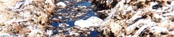
20 Leachate Outbreaks
21 Alternative Daily Cover


22 Leachate Recirculation i


23 Surface Methods: Pre-Cap Tanker Truck Application Spray Irrigation Drip Irrigation Tanker Truck Application Surface Ponds Infiltration Ponds
24 Prewetting Advantages and Disadvantages Advantages simple uniform and efficient wetting promotes evaporation Disadvantages lb labor intensive it i blowing of leachate enhances compaction (may interfere with leachate routing) incompatible with closure
25 Surface Ponds Advantages and Disadvantages Advantages simple construction ti and operation effective wetting directly beneath pond leachate storage provided Disadvantages collect stormwater t floating waste odors limited impact area incompatible with closure
26 Spray Irrigation Advantages and Disadvantages Advantages flexible promotes evaporation Disadvantages leachate blowing and misting surface precipitation leads to decreased permeability cannot be used in inclement weather incompatible with closure
27 Focus on Two Subsurface Methods Horizontal Trenches Shallow systems Deep systems Vertical Injection Wells Large diameter systems Small diameter systems
28 As-Built vs Retrofit As-Built Surface application methods as waste is filled up. Focus on working face. Horizontal trenches buried in the landfill as waste is deposited. Surface systems when complete. Retrofit Surface systems on completed waste fill. Vertical wells. Shallow subsurface horizontal trenches.
29 Vertical Injection Wells Advantages and Disadvantages Advantages relatively large volumes of leachate can be recirculated low cost materials easy to construct during and following waste placement compatible with closure Disadvantages subsidence bid problems limited recharge area interference with waste placement operations
30 Vertical Injection Wells Two major types Large diameter wells Small diameter wells Many of the early leachate recirculation attempts used large diameter wells Most new designs use small diameter wells
31 Large Diameter Vertical Leachate Injection Well
32 Moisture Distribution in Vertical Wells The greatest hydraulic pressure will be at the bottom of the well. This might result in more leachate distribution on the bottom of the landfill.
33 Top of Landfill Vertical Injection Cluster Wells Use multiple small diameter wells. Since more wells are needed, installation must not be cost prohibitive. Top of Sand Drainage Blanket 10 ft
34 Installation of Small Diameter Recirculation Wells: Direct Push Technology
35 Installation of Small Diameter Recirculation Wells: Open Flight Auger
36 Surface and Subsurface Injection Advantages and Disadvantages Advantages low cost materials large volumes of leachate can be recirculated compatible with closure unobtrusive during landfill operation Disadvantages potential ti subsidence impact on trench integrity potential biofouling may limit volume inaccessible for remediation
37 Leach Field GM Cap System Leach Field Trenches Drip Irrigation GM MSW Trenches Surface Methods: Post-Cap MSW


38 Vertical Injection Wells Subsurface Methods Vertical Injection Wells Horizontal Trenches Buried Infiltration Galleries Horizontal Trench
39 Shallow Horizontal ontal Trenches 1. Existing Landfill at Grade 50+ ft MSW Liner and Leachate Collection System
40 Shallow Horizontal 2 Excavate Trench and Trenches 2. Excavate Trench and Install Bedding and Pipe 3-15 ft MSW Liner and Leachate Collection System
41 Shallow Horizontal ontal 3. Backfill Trenches MSW Liner and Leachate Collection System
42 Shallow Horizontal Trenches 4. Additional Trenches ft MSW Liner and Leachate Collection System
43 Shallow Horizontal ontal Trenches 5. Recirculate MSW Liner and Leachate Collection System
44 Shallow Horizontal 5 R i l Trenches 5. Recirculate MSW Liner and Leachate Collection System
45 Deep Horizontal Trenches 1. Install Horizontal Trenches on Lower Lifts ft 15 ft Liner and Leachate Collection System
46 Deep Horizontal Trenches 2. Continue Installing MSW Liner and Leachate Collection System
47 Deep Horizontal Trenches 3. Continue Installing Liner and Leachate Collection System
48 Deep Horizontal Trenches 4. Recirculate Leachate Liner and Leachate Collection System
49 Deep Horizontal Trenches 4. Recirculate Leachate Liner and Leachate Collection System
50 Horizontal Trench Installation Photos: Alachua County SW LF
51
52
53
54 Filling in the trench.
55 Filling in Trench
56 Bioreactor Design - Horizontal Device Placement 8 Latera al Movement t, m Application Rate, m^3/m/day Permeability, cm/s 1E-03 1E-04 1E-05
57 Bioreactor Design - Vertical Well Placement Lateral Movement, m Application Rate, m^3/day Permeability, cm/s 1.0E-3 1.0E-4 1.0E-5


58 Landfill Geotechnical Stability
59 Design Considerations i Shear strength will change during waste degradationd Increased unit weight must be used in design Ensure that moisture increases and injection pressures to not generate excess pore pressures Keep liquids away from slopes
60 Leachate Influences on Stability Additional moisture increases unit weights, reducing FS value Perched leachate can impose hydrostatic head, reducing FS if intersects a failure plane Leachate head on the liner can impose hydrostatic head, reducing FS if intersects a failure plane Injection of liquid id can increase pore pressures, decreases effective stress and mobilizes shear deformation


61 Storage


62
63 Leachate Storage Impact on Off-site Treatment There is a direct relationship between storage and off site treatment t t The more storage available the less leachate must be transported off site for treatment
64 Gas Collection
65 Gas Collection Challenges Higher Gas Temperatures Higher Gas Production Rate (more gas more quickly) Higher Liquid Levels
66 Drill Cuttings from gas well with temps > 150º F


67 Leachate Filled Extraction Trench


68 Gas Pressure
69 Gas Collection Options Vertical Wells Horizontal Collectors Interconnection with leachate system Common Conduit - HYEX System
70 LFG Collection From Operating Landfills Horizontal Collectors o o Sub-Cap Collector o o o o o Leachate Collection System - LFG Collector Network
71
72 Dual lconduit Common trench or piping for gas collection and liquids addition HYEX System uses common carrier drain pipe for separate liquid idinjection and gas collection pipes. Demonstration at Ste. Sophie Landfill, Quebec and Fauquier County, VA


73 Interior of HYEX reinforced landfill conduit; 12 inch ID
74 Terminal end of HYEX conduit with liquid and gas lateral lines and optional CCTV insertion lateral.
75


76 Final Cover
77 Cover System Design Issues Need to keep gas in and allow controlled infiltration ti Greater potential for seeps Increased settlement due to increased degradation and higher waste unit weight
78 Settlement The Keele Valley Landfill - settlement rates of cm/month in wet areas, 5-7 cm/month in dry areas. Yolo County, CA test cells - wet cell settlement rates > three times parallel control cell (17 mos) lower settlement enhancement (~ 5%) was reported at aerobic cells in Columbia Co The Trail Road Landfill in Ontario, Canada reported a 40% recovery of airspace (8 yrs)