AIR OPERATED DIAPHRAGM PUMPS edition 2015 rev 1
|
|
|
- Shauna Copeland
- 5 years ago
- Views:
Transcription


1 AIR OPERATED DIAPHRAGM PUMPS edition 015 rev 1


2 General Where do you use Tapflo pumps? Tapflo pumps are some of the most versatile pumps on the market today. They can be used in a variety of installations in numerous applications. Thanks to the simple operating principle, with a compact and reliable design, Tapflo diaphragm pumps meet the demands of heavy industrial duties. Various liquids Tapflo pumps are compatible with a very wide range of chemicals: Corrosive and chemical aggressive High and low viscous Abrasive Solid laden Shear sensitive Flammable Below you will find some of the most common applications Chemical industry Transfer of all kind of acids, alkalis, alcohol, solvents and shear sensitive products such as latex and emulsions, as well as chemical waste products. Surface conditioning Transport of chemicals from storage tanks, containers and baths, for example in pickling, galvanization and degreasing. Handling of waste products. Water treatment Pumping samples, dosing acids and alkalis for ph-control. Transfer of flocculent, suspensions, chemical reagents and sludges. The pumps are resistant to hydrochloric acid and ferric chlorite, plus many others.


3 General Various liquids... Pulp and paper industry Transport of glue, sodium silicate, colour and titanium oxide etc. Bleaching products, sampling and waste water handling. Hygienic applications Transfer of food products like soup, cream, syrup, milk, yoghurt, flavours, spirit, chocolate, dough, creams, paste, perfumes and toothpaste. Service applications as spraying of cleaning liquid in CIP systems. Mechanical industry Handling of oil, fats, lubricants, cooling liquids, washing and cleaning liquids, solvents and waste products etc. Paint, print and varnish industry Transfer of water- and solventbased paints, ink, varnish, glue, adhesives and solvents. Transfer, recirculation and blendning of ink in printing industies. 5


 The other diaphragm simultaneously transmits the air pressure to the liquid in")


4 General How Tapflo pumps work The Tapflo diaphragm pump is driven by compressed air. The two diaphragms, connected by a diaphragm shaft, are pushed back and forth by alternately pressurising the air chambers behind the diaphragms using an automatically cycling air valve system. Pumped liquid Compressed air First cycle... Second cycle... Suction (1) One diaphragm creates a suction action when being pulled back from the housing. Discharge () The other diaphragm simultaneously transmits the air pressure to the liquid in the housing, pushing it towards the discharge port. During each cycle the air pressure on the back of the discharging diaphragm is equal to the head pressure on the liquid side. Tapflo diaphragm pumps can therefore be operated against a closed discharge valve with no adverse affect to the life of the diaphragms. 1 1 Some benefits with Tapflo pumps Thanks to the simple operating principle, with a compact and reliable construction, Tapflo diaphragm pumps meet the demands of heavy industrial duties. Below are some of the major benefits of Tapflo pumps. Feature Run dry without damage Infinitely variable flow control Few components Self priming up to 5 m from dry suction pipe Solid, strong and long life design Lubrication free air distribution system No electricity needed Air operated Benefit Easy to use, no need of guarding device Flexible and easy to adjust Low down time and maintenance costs More options of installation Low maintenance costs Saves the environment from pollution Explosion proof versions Ex-zone 1 available (ATEX group II, cat ) Can run against a closed pipe or closed valve without damage. Easy to install without special training (no electricity) 6
.")
 products are transfered.")
 from an empty suction pipe and up to 8 meter (6. ) from a wetted pipe.")
5 General How to install Tapflo pumps The Tapflo pumps are flexible in their ease of installation. The in- and outlet ports are infinitely turnable more than 180 in to fit your piping system (PE & PTFE and metal series pumps). Flooded The piping system is designed with a positive suction head. This is the best way of installtion where it is necessary to completely evacuate all liquid from the container, or where viscous (thick) products are transfered. Selfpriming The Tapflo pump is designed to pull a high vacuum. It is able to evacuate an empty suction pipe without any damage to the pump. The suction lift is up to 5 meter (16. ) from an empty suction pipe and up to 8 meter (6. ) from a wetted pipe. The suction capability depends on the pump size (see pages 17,, 9) Submerged All Tapflo pumps may be submerged into the liquid. It is important to make sure that all components which are in contact with the liquid are chemically compatible. The air exhaust must be led to the athmosphere by means of a hose. 7


6 General Key components of the Tapflo pump Three major components are especially vital for the function of the pump... Long life diaphragms With our experience of diaphragm manufacture since 1990, we are able to supply unique technology compression molded diaphragms of outermost quality. Tapflo diaphragms are of composite construction, superior for continuous heavy duty service, with a completely smooth surface in contact with the liquid. This results in no leak through and a diaphragm which is easy to keep clean. The diaphragm is available in various materials and colours to suit any requirements, it is made from PTFE TFM, PTFE TFM modified for solvents, EPDM, NBR or FKM. The PTFE film of the diaphragm forms a closed surface to the liquid. The integrated light metal supporting core and the fabric reinforcement fulfill high strength requirements. Components of PTFE TFM diaphragm An advanced process of preforming, curing, trimming and finishing result in a long life composite diaphragm that will last for many millions of stroke cycles. All compounds are special developed and optimized for composite diaphragm technology and compression molding production. Components are chemically bonded by bonding agents and adhesives. 1) PTFE TFM layer ) Elastomer upper half 3) Core (metal) ) Fabric 5) Elastomer lower half


7 General Key components of the Tapflo pump The energy saving drive, with its central placed air valve is crucial to achieve short air ways and minimum dead volumes. Pollution free air valve The air valve is the driving heart of the pump, distributing the compressed air to the chambers behind the diaphragms. It is made for maintenance free duty with no lube air, thanks to the ingenious sealing system. It will not only save your money for lubrication, it will also save your environment from pollution. The Tapflo air valve has no deadlock position the pump will always start automatically when air is supplied to the pump. The valve body is made from brass or optional PET or stainless steel AISI 316. Energy saving drive After decades of development and fine tuning of the air valve, seals, air distribution ways, the diaphragms and shaft, you have now an air operated diaphragm pump with a very high degree of efficiency. The air valve is placed in the middle of the pump between the diaphragms, to achieve short air ways and a minimum of so called dead volumes. This all together is the key to a reliable and energy saving drive. Ball check valves The Tapflo pump is fitted with four check valves, making sure that the liquid is transferred in the right direction through the pump. The valve is of ball valve type, the most simple and reliable valve design. It has a good sealing capability and is easy to keep clean and to replace if necessary. The valve ball is available in EPDM, NBR (nitrile), PTFE, AISI 316, polyurethane and ceramic to suit any kind of liquid. Flap valves Flap valves are available for the sanitary pumps, ideal in applications with bigger size and delicate solids. The gentle pumping principle will maintain solids without any destruction. Max particle size is 8 mm (with pump T5). 9


, group II, cat, for use in EX-zone 1. Contact us for information.")


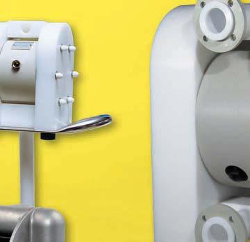
8 Metal series Aluminium and cast iron pumps. Few parts easy to maintain is the major characteristic for these pumps. Tapflo pump range from stainless steel AISI 316, combines superior mechanical strength with chemical resistance. The latest model in the family is the 3 T80 S (pump at top, right side). Metal series pumps The compact, smooth and simple design is common for this series. Materials available are aluminium, cast iron, stainless steel and PTFE coated aluminium. Explosion proof models are available (TX). Certified according to directive 9/9/EC (ATEX), group II, cat, for use in EX-zone 1. Contact us for information. Aluminium and cast iron pumps For transfer of ph-neutral fluids, both thin, thick, solid laden or abrasive. The aluminium and cast iron pumps are found in most fields; work shop and paint industries, purifying plants etc., to mention only a few. AISI 316 stainless steel pumps Made in lost wax cast method, ensuring great accuracy and finish. The stainless steel pumps combine great mechanical strength with good chemical features. AISI 316 is resistant to aggressive liquids like nitric acid and sodium hydroxide. The centre unit, which is not in contact with liquid, is made from corrosive resistant polypropylene (PP) as standard (other materials upon request). The metal pump range 6 sizes, 0-80 lit/min T5* - 6 lit/min, 1/ T70-78 lit/min, 3/ T lit/min, 1 T0-330 lit/min, 1 1/ T0-570 lit/min, T80-80 lit/min, 3 * = aluminium and cast iron only 18

9 Metal series 70% fewer parts You will discover the ingenious simplicity when you maintain the pump. We use approximately 70% fewer parts compared with other brands Flexible installations The connections may be rotated 180. Simply turn the con nections to fit your piping system. Threaded BSP or NPT connections is standard. Twin connections are also avail able.. Powerful valveseats The valve seat is under constant stress from the movement of the valve ball. To obtain the best wear resistant, the integrated seat is made from AISI 316 stainless steel. 3. Low air consumption The air distribution system is designed with shortest possible air distribution ways. This eliminates dead spaces, resulting in high effiencey and low air consumption. Typical applications Industry Workshop Print & paint Mining & construction Ceramic industry Chemistry Example of applications Oil, fat, solvents, water, cooling fluid, lubricants Glue, additives, varnish, ink, paint, latex, acid, resins, pigments Adhesives, sump, dewatering, coal sludge, pastes Abrasives, glaze, water, enamels, clay Acids, alkalis, alcohol, solvents, latex, emulsions Aluminium and cast iron for thick and thin ph neutral liquids Stainless steel for chemi cals 19

10 Metal series Special versions Handle your liquids comfortable. You will easily move your Tapflo drum pump between drums and containers. Drum pumps TD The Tapflo drum pump is ideal for mobile use and is available in aluminium or stainless steel AISI 316. It is fit with an ergonomic designed handle in stainless steel AISI 316L. The drum tube is delivered in any length up to m. The Tapflo diaphragm drum pump has many ad vantages compared with con ventional drum pumps as stated below. The metal drum pumps TXD5-5 lit/min, 1/ TXD70-70 lit/min, 3/ TXD10-10 lit/min, 1 TXD5 is available in aluminium only Feature No rotating parts High pressure Infinitely variable flow Benefit Gentle liquid handling ideal for shear sensitive liquids or abrasive products Able to handle even high viscous products Easy to adjust the flow for a safe fluid handling 0


11 Metal series Special versions PTFE coated pumps Aluminium pump include all wetted parts coated with PTFE, is equipped with stainless steel in/ outlet ports. The model was developed for the printing industry where a low price alternative of the PE/PTFE pumps was required but aluminium not chemically resistant. It can be used for all sorts of applications where slightly acidous or alkaline liquids need to be transferred. However, in applications with highly aggressive chemicals, we still recommend our full plastic PE & PTFE series pumps. Twin pumps TT Tapflo metal series pumps may be equipped with double in/outlet to achieve two pumps in one for blending, mixing or circulation of liquids. The liquid in one pump chamber is separated from the other one. Printing Transfer and circulation of printing ink Application examples Transfer of glue resin and hardener separated from each other Transfer and recirculation of ink to printing machines 1
12 Metal series Performance curves The performance curves are based on water at 0 C. Other circumstances might change the performance. See below how the capacity will change at different viscosities and suction lifts. These curves are valid for all metal pumps. Example (see the red line): A flow of 10 liter/minute is desired. The discharge head is calculated to 0 mwc. We choose a T5. It requires an air pressure of bar and will consume approximately 0.10 Nm 3 air per minute. HEAD PSIG mwc T5 8 0,05 1,77 6 0,10 3,53 0,15 5,30 Air pressure (bar) Air consumption (Nm 3 /min, SCFM) 0,0 7,06 HEAD PSIG mwc T ,10 3,53 0,30 10,6 0,0 7,06 0,0 1,1 Air pressure (bar) Air consumption (Nm 3 /min, SCFM) l/min USGPM CAPACITY l/min USGPM CAPACITY HEAD PSIG mwc T , 7,06 0, 1,1 Air pressure (bar) Air consumption (Nm 3 /min, SCFM) 0,8 8,3 0,6 1, HEAD PSIG mwc T0 8 0,3 10,6 6 0,6 1, 0,9 31,8 Air pressure (bar) Air consumption (Nm 3 /min, SCFM) 1,, l/min USGPM m 3 /h CAPACITY l/min USGPM m 3 /h CAPACITY HEAD PSIG mwc T0 8 0, 1,1 6 0,8 8,3 1,, 1,6 56,5 Air pressure (bar) Air consumption (Nm 3 /min, SCFM),0 70,6 HEAD PSIG mwc T ,0 35,3 1,5 53,0,0 70,6,5 88,3 Air pressure (bar) Air consumption (Nm 3 /min, SCFM) 3, l/min USGPM m 3 /h CAPACITY l/min USGPM m 3 /h CAPACITY Capacity changes Capacity changes at different suction lifts Capacity changes at different viscosities Changes reserved without notice
13 Dimensions for metal series Dimensions in mm (where other is not indicated) Dimensions in inch (where other is not indicated) Metal series Dimensions Aluminium and cast iron pumps T Dim Pump size ** A B B D D D E E E F G G H H I I J 1/ 3/ 1 1 1/ DN80(3 ) 1/ 3/ 1 1 1/ DN80(3 ) J 3/8 1/ 3/ 1 1 1/ - 3/8 1/ 3/ 1 1 1/ - ØK L 1/8 1/ 1/ 1/ 1/ 3/" 1/8 1/ 1/ 1/ 1/ 3/ M M N N P P R S ØT U 170* 170* 170* * 50.0* 50.0* V * = Any length up to 000 mm on request * = Any length up to 79 on request Stainless steel pumps T Drum pumps TD Twin pumps TT ** = T80 stainless steel has other design than shown above, contact us for drawing. General dimensions only, ask us for detailed drawings. Changes reserved without notice 3
14 Metal series Technical data Data Pump size General characteristics *Max capacity (l/min) / (US gpm) 6 / / / / / / 16 **Volume per stroke (ml) / (cu in) 70 / / / / / /31.7 Max discharge pressure (bar) / (psi) 8 / 116 Max air pressure (bar) / (psi) 8 / 116 *** Max suction lift dry (m) / (Ft) 1.5 /.9 3 / 9.8 / 13 / 13 / 13 5 / 16 Max suction lift wet (m) / (Ft) 8 / 6 Max size of solids (ø in mm) / (in) 3 / 0.1 / / / / / 0.59 Max temp with EPDM/NBR ( C) / ( F) 80 / 176 Max temp with PTFE ( C) / ( F) 110 / 30 Min temperature ( C) / ( F) -0 / - Weight Standard pump in alu (kg) / (Ib) /. 5 / 11 8 / / 3 / / 13 Standard pump cast iron (kg) / (Ib) 7 / / 17 / 37 / / Standard pump in AISI 316 (kg) / (Ib) - 7 / / / 8 68 / / 319 Drum pump TD in alu (kg) / (Ib) 3 / / / Drum pump TD in AISI 316 (kg) / (Ib) - 9 / Material of components Pump housing and all wetted aluminium, cast iron or AISI 316L aluminium metal details or AISI 316L Centre block, alu and cast iron pumps aluminium (standard) or cast iron aluminium Centre block, AISI 316 pumps - PP (standard) or conductive PP - Diaphragms NBR, PTFE, PTFE 1705B or EPDM Valve balls NBR, PTFE, AISI 316L****, EPDM, polyurethane or ceramic**** Air valve Brass / NBR (standard) or AISI 316L / FKM or PET / NBR (standard on TX80) O-rings EPDM, NBR or FKM Gaskets Housing screws Steel on aluminium and cast iron pumps, AISI 30 on stainless steel pumps Diaphragm shaft Stainless steel AISI 30 Drum handle (TD pumps) Stainless steel AISI 316L - * = Recommended flow is half of the the max flow, i.e. recommended flow for a T10 is 60 l/min (15.9 US gpm). ** = The value is based on pumps with EPDM diaphragms. Pumps with PTFE diaphragms have about 15% less volume. *** = This is max value with stainless steel valve balls, other valve ball materials may reduce the suction. Please consult us. **** = Not available on TX80. Pump code The pump code details the specification, maximum capacity and materials of the major components. Tapflo diaphragm pump Max capacity (l/min) Material of wetted metal parts: A = Aluminium C = Cast iron S = Stainless steel AISI 316 X = PTFE coated aluminium Material of diaphragms: B = PTFE 1705B (solvents) E = EPDM N = NBR (nitrile rubber) T = PTFE V = FKM (sizes 5 and 70) T XD 70 A T T -7BV Basic options: B = Backup diaphragm system D = Drumpump F = Filterpress pump L = Valve lift system (drain system) P = Powder pump T = Twin pump (double in/outlet) X = ATEX approved, group II, cat Material of valve balls: E = EPDM N = NBR (nitrile rubber) T = PTFE S = AISI 316 stainless steel P = PU (polyurethane) K = Ceramic V = FKM Special executions*: 1 = Optional material in/outlet 3 = Optional connections = Backup diaphragm system configuration 5 = Other special executions* 6 = Optional material of centerblock 7 = Optional material of air valve 8 = Optional material of pos 18 seals 9 = Optional material of housing screws 1 = Powder pump options 1 = Optional pump feet * = Ask us for complete pump code with all available options and executions. Changes reserved without notice