THERMOSET. 1.Resin Transfer Moulding 2.Pultrusion 3.SMC / DMC Moulding 4.Compression Moulding 5.GRP Moulding 6.RIM 7.
|
|
|
- Prosper Wells
- 5 years ago
- Views:
Transcription
1 Polymer Processing Plastics Rubber Thermoplastics Elastomers Fibers Plastics
2 Plastics Processing Conversion of a plastic materials in to finally finished products is termed plastics processing. Depends on melt flow behaviour and thermal properties of materials. Three steps are involved in converting plastics granules/power in to the required shapes. 1. Pre processing a) Compounding of additives with different formulation b) drying 2. Primary processing 3. Post processing a) welding b) Joining and Machining c) Decoration of products by printing d) Surface treatment e) Thermoforming f) Biaxially oriented film.
. 2.")

3 Plastics Processing Plastics Processing involves 3 key stages: 1. Heating to liquid state T > Tm or Tg (amorphous polymers). 2. Forming to required shape under pressure p up to 108 Pa (1 kbar) 3. Cooling to solidify Generally quenched-in nonequilibrium structure (chain orientation, orientation and fraction of crystallities,...) Aim : Correct shape + property enhancing microstructure Heating Shaping Cooling
4 Polymer processing There are a variety of different processing methods used to convert resins into finished products. Some include: THERMOPLASTICS Extrusion Injection moulding Blow Moulding Rotational Molding THERMOSET 1.Resin Transfer Moulding 2.Pultrusion 3.SMC / DMC Moulding 4.Compression Moulding 5.GRP Moulding 6.RIM 7.Foam Production


5 Polymer processing There are a variety of different processing methods used to convert resins into finished products. Some include: Extrusion Profile and Sheet extrusion Pipe extrusion Cast film extrusion Blown film extrusion
6 Polymer processing There are a variety of different processing methods used to convert resins into finished products. Some include: Injection Moulding Common Injection Moulding Insert Moulding Gas Assisted Injection Moulding Structural Foam Moulding Reaction Injection Moulding Injection Blow Moulding


7 Polymer processing There are a variety of different processing methods used to convert resins into finished products. Some include: Blow Moulding Injection Blow Moulding Extrusion Blow Moulding Stretch Blow Moulding


8 Polymer processing There are a variety of different processing methods used to convert resins into finished products. Some include: Thermo forming Vacuum Forming Pressure forming
9 Thermoforming Thermoforming is a method of manufacturing custom plastic enclosures by preheating a flat sheet of plastic and bringing it into contact with a mold whose shape it takes. This can be done by vacuum, pressure and or direct mechanical force.

10 Pressure Forming Pressure forming involved forcing a hot plastic sheet against a mold by introducing compresses air to the sheet's outer side.
11 Vacuum Forming It involves the automatic draping of a heat- softened plastic sheet over a female or male mold.
12 Injection Moulding Plunger type The main problem with a straightforward plunger arrangement was that no melt mixing or homogenisation could be readily imparted to the thermoplastic material
13 Injection Moulding Reciprocating screw injection moulding unit
14 Injection Moulding Injection Moulding Process 1. Screw Plasticating 2. Moulding
15 Injection Moulding Material is introduced into the injection moulding machine via a Hopper. The injection moulding machine consists of a heated barrel equipped with a reciprocating screw (driven by a hydraulic or electric motor), which feeds the molten polymer into a temperature controlled split mould via a channel system of gates and runners. The screw melts (plasticizes) the polymer, and also acts as a ram during the injection phase. The screw action also provides additional heating by virtue of the shearing action on the polymer. The polymer is injected into a mould tool that defines the shape of the molded part.
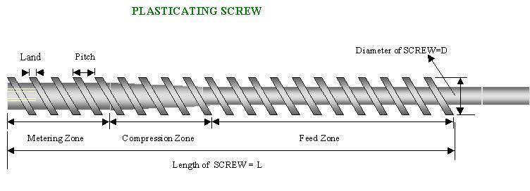
16 PLASTICATING Plasticating refers to conversion of plastic granuals to flow-able melt. It happens inside the screw barrel assembly of the injection unit in the Injection Moulding Machine.
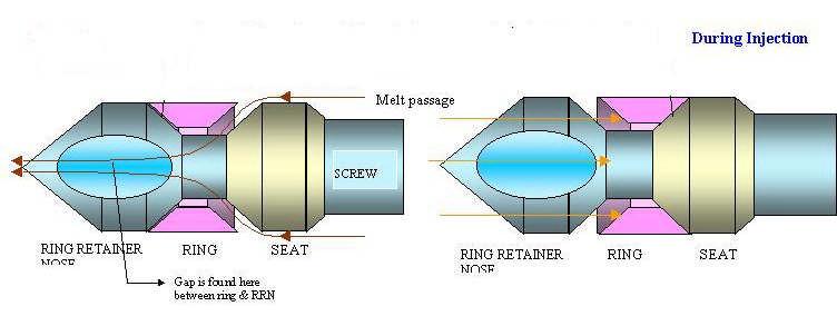
17 PLASTICATING- How? The plastic granules move inside the screw channel when screw is rotated. The screw has three sections. FEED ZONE, COMPRESSION ZONE and METERING ZONE. In the compression zone the material is gradually compressed. It therefore rubs against the barrel wall. This sets up shearing forces on the material. Plastic material under shear changes its viscosity. This is SHEAR THINING characteristic of plastics. Melt is then homogenised in metering zone. At the tip of the screw, non- return valve is fitted. It allows the melt to flow ahead through this valve while screw is rotated. Non return valve does not allow the melt to slip back through it to the screw channel.
18 Feed Zone The Feed zone flights are long and designed to move the material along the barrel as quickly as possible. As they move along, the granules are heated by friction (from the movement of the screw inside the barrel and from the movement of the granules themselves) and by the inside of the barrel against which the granules are forced by movement of the flight
19 Compression Zone In the Compression zone the flights become shorter and the plastic granules are further heated and compressed, removing any air pockets. The plastic is melted by now and becomes thoroughly mixed or homogenized by the continuing movement of the screw.
20 Metering zone The Metering zone contains the shortest flights, which are designed to pump the plastic or melt, through the injection/extrusion die.
21
22 Screw The characteristics of the screw are crucial indetermining the type and size of product that can be produced on an Injection Moulding Machine. One of the most important factors is the ratio between the length and the diameter, or the L/D ratio. 22:1 or higher (meaning that the screw is 22 times the length of the diameter) improves the mix of the melt and the quality of the product. Generally speaking for high quality products such as engineering components, a L/D ratio of 22:1 or higher is needed. 20:1 is suitable for medium quality products like garden furniture and 18:1 would typically be used for low quality items such as disposable packaging or cheap children s toys.
23 Terms in Injection moulding Short Weight: The Shot Weight of a machine is defined as the weight of plastic produced at the nozzle in a normal cycle (without a mould) in PS (specific gravity 1.05). INJECTION PRESSURE This is the pressure in the barrel at the point of injection, expressed in kg/cm2 or kbar. A higher L/D ratio produces greater Injection Pressure. The greater the Injection Pressure the better the the better the quality of product produced.
24 Terms in Injection moulding INJECTION STROKE The distance that the screw travels during an injection stroke, up to 4 * diameter. INJECTION VOLUME Theoretically, the injection volume is the length of the injection stroke multiplied by the cross sectional area of the screw. only around 90% of that Injection Volume gets injected.
25 INJECTION SPEED INJECTION RATE :This is the volume of melt produced by the screw, expressed in cm3 per second. SCREW ROTARY SPEED
26 CLAMP FORCE The melt is injected into the mould under very great pressure, which the mould halves, and any other components or cores, must be able to resist in order to maintain their shape and to avoid any seepage. The larger a component is, the greater the pressure and so, the greater the Clamp Force required.
27 MOULD OPENING STROKE This is the distance that the moving mould half moves from mould closed to mould open. MOULD HEIGHT This should be called Mould Thickness,
28 Moulding Moulding refers to shaping of plastic melt inside the mould.


29 INJECTION MOULDING MACHINE FOR PREFORMS 1987 HUSKY XL 225 P
30 THREE BALANCING TRICKS I can summarize the successful and consistent moulding to three balancing tricks; Flow balancing part geometry dependent. Heat balancing in one cycle time- dependent on design of cooling in the mould and cooling water supply system. Uniform freezing of melt in the mould. Dependent on cooling design and supply system. Any unbalancing on the above three balances will result in moulded-in stress. This is the biggest culprit for over 50% part failure
31 Applications of Injection moulded Power-tool housing Telephone handsets Television Cabinets Electrical Switches DVDs Automotive bumpers Automotive dash boards Battery Casings Syringes Drug Inhalation Units Disposable razors Washing-up bowls Wheelie binscrates/ Recycling boxes Bottle Lids/closures parts
32 Types of Injection Moulding Multi-shot (or 2K moulding) (where different materials are injected into the same mould), Insert moulding (where metal components are incorporated). Structural foam moulding (where the material is foamed to reduce density) Gas assisted moulding (where gas is in corporated to reduce wall thickness).

33 Insert Moulding Insert moulding ABS, PA, PC, GPPS,PP
34 Structural Foam Moulding Structural Foam is a term commonly used to describe thermoplastic injection moulding components made by the injection moulding process which have a cellular core.
35 Gas Assisted Moulding The main two types of Gas Assisted Moulding are Either inject the gas into the component cavity (internal gas injection), Or to use the gas on the outside surface, but still within the mould cavity, to consolidate the component (external gas injection). Internal Gas Injection - Most widely used process External Gas Injection - used for enhanced surface definition
36 Gas Assisted Moulding Automotive Bumper Dash Panel
37 External Gas Assisted Moulding Applications: Flat panels for office equipment. Computer enclosures. Furniture, i.e. tabletops. Automotive panels. Domestic appliances
38 EXTRUSION
39 The extrusion process
40 Introduction Extrusion: (Greek) push out Pump supplies a continuous stream of material to a shaping tool or to some other subsequent shaping process. Materials plastics metals (Al window frames spaghetti and other noodles toothpaste Extrusion useful for shaping parts with extruder dies Extrusion is basis for injection molding and blow molding
41 The extrusion process Plastic granulate is supplied via the feed hopper to the extruder Homogenous melted material from thermoplastic granulate under high pressure in an extruder (screw press) or co-extruder Shaping of the molten mass to a continuous web by means of flat sheet dies Calibration of the emerging material to the desired thickness using a 3-roller flattening calender Tension-free cooling of the web to ambient temperature Cutting to required width and length and subsequent stacking on pallets
42 Extrusion Extruder Equipment Exit zone- die die imparts shape on the material, e.g., rod, tube, sheet, channel exit material is called extrudate extrudate swells at end of die due to normal forces from the polymer flow, called die swell Cooling zone water bath or air cooled to lower the temperature below Tg Auxiliary equipment puller rollers for proper thickness Wind-up or cut off

43 Single screw extruder
44 Single screw Most common Extruder Types A screw rotates in a cylinder and creates a pumping action. Twin Screw Twin screws have more positive pumping action than single screws and can be used for higher output. Co-Rotating Twin Screw: popular for compounding Counter- rotating Twin Screw Extruders
45 Extrusion Principle Continuously shaping a fluid polymer through an orifice of a suitable tool (die), and subsequently solidifying into a product. Equipment Single screw extruder consists of Screw, barrel, feed hopper, and die Common extruders are rated by barrel bore diameter (0.75 to 6 ) Plastics extruders can be 24 diameter and 48 ft in length Electric heaters for barrels and Air (or water bath) coolers for extrudate Screw is matched to material produced Simple screw has flights and decreasing gaps along channel Screw Aspect (L/D) ratio = screw length to screw diameter (range 20-30) Venting zone for gases that evolve during processing Twin screw- used for shear sensitive materials (e.g., PVC)
46 Plastic Extrusion Sheet Extrusion Profile Extrusion Pipe extrusion Co-extrusion Blown Film Extrusion Cast Film Extrusion Foam Extrusion Pultrusion Calendering


47 1 Drive unit 2 Barrel inlet 3 Temperatue control 4 Feed hopper and dosing unit 5 Vacuum venting 6 Barrel 7 Screws

48 Single screw extruder


49 1 Drive unit Powerful, low Powerful, low-noise gearbox, with hardened and ground gear wheels in a cast housing with oil immersion lubrication. Direct drive by means of clutch, with either AC or DC technology.
50 EXTRUDER Extruder Extruder base- used to isolate extruder and to reduce vibrations Drive motor- turns the screw and provides power for operation. Extruder power capacity- key characteristic on extruder Power increases as polymer output increases barrel diameter increases screw length increases requirements for high output at high polymer temperature Thrust bearing is mounted on the screw near where the screw attaches to the linkage. It prevents the screw from moving backwards and absorbs the thrust of the screw as it turn against the resistance of the resin.
51 L\D ratio Maximum 20 for elastomers More than 20 for thermoplastics.
52 Hopper
53 Barrel
54 Screw Extruder screw Function conveying resin through extruder imparting mechanical energy to melt the polymer mixing ingredients together building pressure to push resin through die Type Single screw Twin-screw Length/diameter (L/D) ratio: Length of flighted portion of the screw to the inside diameter of the barrel. L/D is a measure of the capability of the screw to mix and melt materials. High L/D ratios indicate good mixing and melting capabilities, e.g. 32:1
55 Sheet Extrusion Sheet extrusion is a technique for making flat plastic sheets from a variety of resins
56 Sheet Extrusion Applications Within the building and construction industries, sheet extrusion is used for a variety of applications. One of the main uses of extruded PS sheet is for thermal insulation materials for walls, roofs, and under floors. In the automotive industry, sheet is currently used to produce interior trim, panels, and dashboards. Foamed polyolefin sheet, both cross-linked and non- cross-linked, is also used in automotive applications. There are a number of other applications where thermoformed sheet plays a significant role. These include the manufacturing of luggage, refrigerator liners, and shower units.

57 Profile/Pipe Extrusion This process is used to manufacture plastic products with a continuous crosscross-section such as; drinking straws, plastic Pipes and profiles.
58 Blown Film Extrusion (Film Blowing) Blown film extrusion is the process by which most commodity and specialized plastic films are made for the packaging industry. The film blowing process basically to form a thin tubular product that can be used directly, or slit to form a flat film.


59 Blown film process Plastic melt is extruded through an annular slit die. Air is introduced via a hole in the centre of the die to blow up the tube like a balloon. Mounted on top of the die, a high--speed air ring blows onto high the hot film to cool it. The tube of film then continues upwards, continually cooling, until it passes through nip rolls where the tube is flattened to create what is known as a ' lay--flat' tube of film. lay Air inside the bubble is also exchanged. This is known as IBS (Internal Bubble Cooling).


60 Cast Film Extrusion In a cast film extrusion process, a thin film is extruded through a slit onto a chilled, highly polished turning roll, where it is quenched from one side
61 Blow Moulding Blow moulding is used to create hollow enclosed components and there are two basic types of technology extrusion blow moulding and injection blow moulding and stretch blow moulding. In extrusion blow moulding a parison or tube is produced by extrusion. A mould is then closed around the parison and the product is blown into the shape of the mould with compressed air.
62 Extrusion Blow moulding Process The blow moulding machine is based on a standard extruder barrel and screw assembly to plasticise the polymer. The molten polymer is led through a right angle and through a die to emerge as a hollow (usually circular) pipe section called a parison. When the parison has reached a sufficient length a hollow mould is closed around it. The mould mates closely at its bottom edge thus forming a seal. The parison is cut at the top by a knife prior to the mould being moved sideways to a second position where air is blown into the parison to inflate it to the shape of the mould. After a cooling period the mould is opened and the final article is ejected.to speed production several identical moulds may be fed in cycle by the same extruder unit.

63 The process is similar to injection moulding and extrusion. 1. The plastic is fed in granular form into a 'hopper' that stores it. 2. A large thread is turned by a motor which feeds the granules through a heated section. 3. In this heated section the granules melt and become a liquid and the liquid is fed into a accumulator. From accumulator melt is pushed to form parison throuh the die in to the mould. 4. Air is forced into the mould which forces the plastic to the sides, giving the shape of the bottle. 5. The mould is then cooled and is removed.
64 Injection blow moulding In injection blow moulding two moulds are used. A mandrel or blowing stick is placed in the first mould, and the thermoplastics material is then injected into the mould flowing around the mandrel to create a tube. This is then transferred to the second mould where air is introduced to expand it to the shape of the mould. A variation on this method is stretch blow moulding whereby the material is biaxially oriented to produce stronger products. This method is particularly used for the manufacture of PET bottles.
65 Applications Bottles and containers Automotive fuel tanks Venting ducts Watering cans Boat fenders etc
66 Rotational Moulding Rotational moulding is a process used for producing hollow plastic products. Rotational moulding differs from other processing methods in that the heating, melting, shaping, and cooling stages all occur after the polymer is placed in the mould, therefore no external pressure is applied during forming.
67 Rotational Moulding This provides the following advantages: Economically produced large products Minimum design constraints StressStress-free products No polymer weld lines Comparatively low mould costs
68 The Process 4 Stages Charging Mould A prepre-determined amount of polymer powder is placed in the mould. With the powder loaded, the mould is closed, locked and loaded into the oven. The powder can be prepre-compounded to the desired colour.. colour Heating & Fusion Once inside the oven, the mould is rotated around two axis, tumbling the powder the process is not a centrifugal one. The speed of rotation is relatively slow, less than 20 rev/min. The ovens are heated by convection, conduction and, in some cases, radiation. As the mould becomes hotter the powder begins to melt and stick to the inner walls of the mould. As the powder melts, it gradually builds up an even coating over the entire surface. Cooling When the melt has been consolidated to the desired level, the mould is cooled either by air, water or a combination of both. The polymer solidifies to the desired shape. Unloading/Demoulding Unloading/ Demoulding When the polymer has cooled sufficiently to retain its shape and be easily handled, the mould is opened and the product removed. At this point powder can once again be placed in the mould and the cycle repeated.