Continuous Synthesis of Carbon Nanoclusters Using Well-Controlled Thermal Plasmas
|
|
|
- Doris Harrison
- 5 years ago
- Views:
Transcription
1 Continuous Synthesis of Carbon Nanoclusters Using Well-Controlled Thermal Plasmas T. Ohishi*, Y. Yoshihara and O. Fukumasa Graduate School of Science and Engineering, Yamaguchi University, Tokiwadai, Ube, Yamaguchi , Japan Corresponding author: Fax: Abstract A continuous synthesis technique to produce carbon nanoclusters such as multi-walled carbon nanotubes (MWCNTs) or carbon nanofibers (CNFs) is studied by using a well-controlled plasma jet. In this method, numerous fiber-like structures can be produced. Production of carbon nanoclusters are well enhanced by additionally injecting Ni powders compared with production by using only CH 4 / H 2 gas mixtures. Effect of Ni powder injection, i.e. behaviors of Ni powders and production mechanism are briefly discussed. Keywords: carbon nanoclusters; well-controlled thermal plasmas; dc plasma jet 1
2 1. Introduction Recently, much attention has been paid to carbon nanoclusters such as carbon nanotubes (CNTs) or carbon nanofibers (CNFs). They are characterized by some of physical and mechanical properties. Especially, CNTs have many interesting characteristics that are electronic, mechanical and thermal properties. 1) On preparation of carbon nanoclusters, arc discharge, laser ablation and chemical vapor deposition (CVD) methods are mainly used. 2,3) CNTs prepared by the arc discharge method have a higher degree of crystallinity and a lower number of defects than those prepared by CVD. 4) But, at the same time, diameters of CNTs produced by the arc discharge method are distributed in a wide range. In addition, this method is basically not a continuous but a discontinuous process. Thermal plasma processing using a plasma jet with a high speed and a high heat capacity is one of the most promising methods for synthesizing new materials. The well-controlled thermal plasma reactor which we have newly developed can produce a plasma jet with high stability and high thermal efficiency for various operating conditions. 5) So far, we have reported the rapid synthesis of ferrite particles from powder mixtures 6) and diamond films from CH 4 / H 2 gas mixtures 7) using this reactor with relatively low power operation. The synthesis of carbon nanoclusters or CNTs using a plasma jet was studied by some authors 8-11). Usually, for production of carbon nanoclusters, catalysts (for example Fe, Co and Ni) are 2
3 needed and the reactor is operated with high power. Namely, arc current is high (300 A). Therefore, we have undertaken to study application feasibility of our thermal plasma reactor for continuous synthesis method of carbon nanoclusters. Until now, we have confirmed that numerous fiber-like structures can be produced on a Si substrate readily by using only CH 4 gas as material gas, 12) and that production of these carbon nanoclusters are enhanced both by adding H 2 gas as an assist gas and by using Ni substrate. 13,14) Therefore, in this paper, we study further mass production of carbon nanoclusters. Effects of Ni powders injection, i.e. behaviors of Ni powders as a catalyst are studied. Production mechanism and optimum conditions for carbon nanoclusters synthesis are also discussed briefly. 2. Experimental set-up and procedure The schematic diagram of the plasma jet reactor system is shown in Fig. 1. The reactor consists of a forced constricted-type plasma jet generator (Cu nozzle anode of 5 mm in diameter, Cu-insulated constrictor nozzle of 5 mm in diameter, and rod cathode made of 2 % Th W), a feed ring (nozzle of 5 mm in diameter), a reaction chamber (370 mm in width, 390 mm in depth, 610 mm in length) and a substrate holder. 6,7,12-14) Experiments are performed under continuous pumping and flowing of Ar gas. The 3
4 plasma jet is produced by direct-current arc discharge between the nozzle anode and the rod cathode. As the insulated constrictor nozzle is set between the nozzle anode and the cathode, arc length is always kept constant and the nozzle wall strongly constricts the arc with the working gas. Then, a stable plasma jet with high heat capacity is produced under various operating conditions. 5-7) For synthesis of carbon nanoclusters, CH 4 gas is used as material gas and H 2 gas is used as assist gas. The CH 4 gas and H 2 gas are injected into the plasma flow of a high-temperature region directly through two capillary feeding ports of the feed ring. These starting materials decompose into small fragments. Then, atomic carbon and hydrogen are prepared. With the injection of H 2 gas, amorphous carbon is removed and the production of carbon nanoclusters is enhanced. 13,14) Within the present experimental conditions, production of carbon nanoclusters is nearly optimized when the ratio of material gas (CH 4 ) flow rate Q m to assist gas flow rate Q a, Q m / Q a, is about Therefore, in the present experiments, the preparation of nanoclusters is examined with H 2 gas injection at this ratio. The gas mixtures and/or Ni powders are injected into the plasma flow of a high-temperature region directly through two capillary feeding ports of the feed ring. Throughout the present experiments, experimental conditions are as follows: Working gas (Ar) flow rate Q w is 20 l/min; jet power W j is 5 kw; distance from the feed ring exit to substrate L is varied from 80 to 100 mm; pressure in the reaction chamber P t is 760 Torr; 4
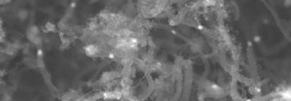
5 material gas (CH 4 ) flow rate Q m is 0.3 l/min; assist gas (H 2 ) flow rate Q a is 8 l/min; Ni powder flow rate Q Ni is varied from 0.02 to 0.2 g/min; processing duration time T is varied from 30 s to 10 min; mean diameters of injected Ni powders are 40 μm and 20 μm; and substrate material is Si. Prepared products are characterized by scanning electron microscope (SEM), energy dispersing X-ray (EDX) analysis and Raman spectroscopy. 3. Experimental results and discussion The effect of catalysts on carbon nanocluster synthesis is studied. Ni is one of the catalysts commonly used in the synthesis of CNTs. At first, we test the effect of Ni powder injection and the processing duration time for production of carbon nanoclusters. Figure 2 shows SEM images of the products on the Si substrate with using Ni powders for various processing duration times T; T = 30 s in Fig. 2(a), 5 min in Fig. 2(b), 10 min in Fig. 2(c) and 20 min in Fig. 2(d). In these cases, during 30 s from the beginning of the process, Ni powders are injected into the plasma jet simultaneously with CH 4 and H 2 gases through the feed ring. After that, only CH 4 and H 2 gases are injected continuously. Mean diameter of injected Ni powders is about 40 μm. In Fig. 2(a), fuzz-like structures are observed on the Ni particles sprayed on the 5
6 substrate after plasma processing. As is shown clearly in Figs. 2(b)-(d), many carbon nanoclusters are observed. In these cases, white particles are also observed inside of the carbon nanoclusters. According to the SEM images of Figs. 2, diameters of carbon nanoclusters are nearly the same size as the diameter of white particles and are distributed in a certain range, i.e nm. Next, we identify the white particles observed inside of the carbon nanoclusters. Figure 3(a) shows a SEM image of magnified view of the products shown in Fig. 2(b). Two white particles can be observed inside of the fiber-like structures. The diameters of the products are nearly equal to the diameters of white particles, and are about 500 nm. Figure 3(b) shows the result of line analysis with using the EDX analysis along the line drawn on the two white particles as shown in Fig. 3(a). Two peaks of Ni are observed clearly just on the two white particles, respectively. It is also confirmed that the products are composed of two elements, namely, C and Ni. From these results, we confirm that white particles are Ni particles. According to the Ref. 15, the diameter of the carbon nanoclusters is nearly the same as the diameter of the catalysts. Therefore, the diameter of the synthesized carbon nanoclusters might depend on the size of Ni particles on the substrate. According to the results shown in Fig. 2, it can be suggested that growth of carbon nanoclusters is started from Ni particle prepared through plasma processing. It is not clear, 6
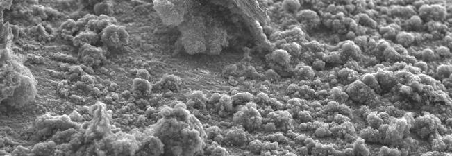
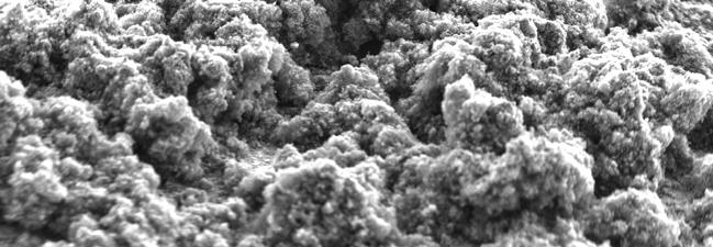
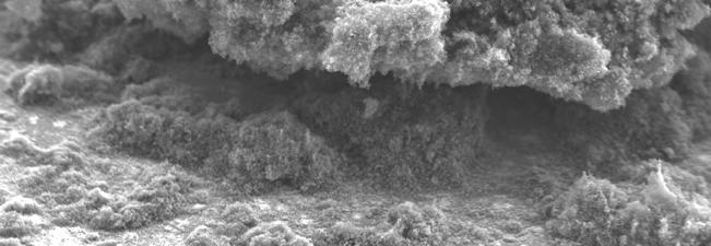
7 however, where is the origin prepared. Then, we discuss the origin of carbon nanoclusters and also discuss whichever of gas-phase reaction and surface reaction is the main reaction in our plasma jet processing. To this end, another approach is tested for preparation of carbon nanoclusters. Namely, during 30 s from the beginning of the process, only Ni powders are injected into the plasma jet through the feed ring with H 2 gas. After this process, CH 4 and H 2 gas mixtures are injected continuously. Mean diameter of injected Ni powders are about 40 μm. Figures 4, 5 and 6 show SEM images of the products on the Si substrate for three different conditions. Namely, Ni powder flow rate Q Ni = 0.02 g/min in Fig. 4, 0.1 g/min in Fig. 5, and 0.2 g/min in Fig. 6, respectively. Ni powder flow rate is controlled by changing the rotating speed of disk of powder feeder. After pre-preparation of the Si substrate with Ni powder injection, surface of the Si substrate are varied for different Ni powder flow rate. When Q Ni = 0.02 g/min, Ni powders are sprayed in patches on the Si substrate. With increasing Ni powder flow rate, Ni is sprayed fully on whole area of the Si substrate. Figures 4(a), 5(a) and 6(a) show SEM images of bundles on the Si substrate. Amount of the bundles that contain carbon nanoclusters are increased with increasing flow rate of Ni powders. Figures 4(b), 5(b) and 6(b) show SEM images of the magnified view of products. Numerous fiber-like structures are clearly observed. The diameters of the fiber-like structures 7
8 are distributed from 40 to 100 nm. Amount of fiber-like structures are also increased with increasing flow rate of Ni powders. In addition, the diameter of the fiber-like structure seems to be nearly the same within three different cases. Ni particles are also observed inside of the fiber-like structures as shown in Figs. 2 and 3. These fiber-like structures are prepared under the large bundles. So, it is considered that most fiber-like structures are grown up from the back of the Ni layer prepared with Ni powder injection. However, relationship between fine-structure of prepared Ni layer and Ni powder flow rate is now under study. Finally, we discuss whether production of carbon nanoclusters depend on the mean diameter of injected Ni powders or not. Nanoclusters are prepared by the same process described above with using another Ni powders (mean diameter is about 20 μm). But, there is no clear difference in the products between two cases, i.e. using 20 μm and 40 μm powders. It suggests that fine structure of prepared Ni layer is scarcely varied by changing powder diameter from 40 μm to 20 μm. As a whole, production of carbon nanocluster is well enhanced with injecting Ni powders. According to the present experimental results and discussion, it is confirmed that origin of growth point is prepared with surface reaction. Reaction process is as follows: At first, the Si substrate is coated with spraying Ni powders, then surface of prepared Ni layer becomes finely-resolved. Atomic carbons are easily prepared from CH 4, heated and 8
9 accelerated in the plasma jet. These carbons are collided with prepared Ni layer and melted into Ni particles. Then, carbon nanoclusters start growing up from the Ni particles whose diameter is suitable for synthesizing carbon nanoclusters. 4. Summary We have studied synthesis of carbon nanoclusters such as multi-walled carbon nanotubes (MWCNTs) or carbon nanofibers (CNFs) using the thermal plasma reactor. Production of carbon nanoclusters are well enhanced by injecting Ni powders compared with production by using only CH 4 / H 2 gas mixtures. Main reaction for origin production is surface reaction in the present process. The diameter of the synthesized carbon nanoclusters might depend on the size of Ni particles on the substrate. In the future, with optimizing process conditions (i.e. jet power, flow rate, pressure, substrate temperature and position), we will study whether diameter of carbon nanoclusters could be controlled or not by varying injection of Ni powders. On production of carbon nanoclusters, difference between using Ni powders and using Ni substrate should be also clarified from the view point of mass production. Acknowledgements 9
10 The authors would like to thank S. Fujimoto of Yamaguchi University for his support in the experiment. Part of this work was supported by a Grant-in-Aid for Scientific Research (A) from Japan Society for the Promotion of Science. 10
11 References 1) S. Iijima: Nature 354, 56 (1991). 2) C. Journet, W. Maser, P. Bernier, A. Loiseau, M. L. Chapelle, S. Lefrant, P. Deniard, R. Lee and J. E. Fische: Nature 388 (1997) ) Y. Yabe T. Ishitobi, Y. Show and T. Izumi: Diamond Relat. Mater. 13 (2004) ) J. Hann, J. H. Han, J. E. Yoo, H. Y. Jung and J. S. Suh: Carbon 42 (2004) ) O. Fukumasa: Oyo Buturi 67 (1998) 181 [in Japanese]. 6) O. Fukumasa and T. Fujiwara: Thin Solid Films 435 (2003) 36. 7) S. Sakiyama, O. Fukumasa, T. Murakami and T. Kobayashi: Jpn. J. Appl. Phys. 36 (1997) ) K. Yoshie et al., Appl. Phys. Lett. 61 (1992) ) C. M. Lee, S. I. Choi, T. H. Hwang and S. H. Hong: Abstract 7th Asia Paciffic Conf. Plasma Sience and Technology / 17th Symp. Plasma Science for Materials, 2004, p ) S. I. Choi, J. S. Nam, J. I. Kim, T. H. Hwang, J. H. Seo and S. H. Hong: Abstract 7th Asia Paciffic Conf. Plasma Sience and Technology / 17th Symp. Plasma Science for Materials, 2004, p ) J. Hahn, J. H. Han, J. E. Yoo, H. Y. Jung and J. S. Suh: Carbon 42 (2004) ) Y. Yamatani and O. Fukumasa: Proc. Plasma Science Symp / 22nd Symp. Plasma Processing, 2005, p ) Y. Yamatani and O. Fukumasa: Jpn. J. Appl. Phys. 45, (2006). 14) T. Ohishi and O. Fukumasa: Proc. 24th Symp. Plasma Processing, 2007, p ) Y. B. Zhu, W. L. Wang, K. J. Liao and Y. Ma: Diamond Relat. Mater. 12 (2003)
12 Figure Captions Fig.1 Schematic diagram of thermal plasma reactor system with forced constricted-type plasma jet generator. Fig.2 SEM images of carbon nanoclusters prepared on the Si substrate with Ni powders for various processing duration time : (a) T = 30 s (b) T = 5 min (c) T = 10 min (d) T = 20 min. The experimental conditions are as follows : P t = 760 Torr, W j = 5 kw, L = 80 mm, Q w = 20 l/min, Q m = 0.3 l/min, Q a = 8.0 l/min, Q Ni = 0.2 g/min and mean diameter of injected Ni powders is 40 μm. Fig.3 Characterization of carbon nanoclusters prepared on the Si substrate, where T = 5 min : (a) the magnified SEM image of products in Fig. 2(b), and (b) line analysis results by using the EDX analysis. Fig.4 SEM images of carbon nanoclusters prepared on the Si substrate, Q Ni = 0.02 g/min : (a) SEM image and (b) the magnified SEM image of products. Experimental conditions except Q Ni are the same as ones in Fig. 2. Fig.5 SEM images of carbon nanoclusters prepared on the Si substrate, Q Ni = 0.1 g/min : (a) SEM image and (b) the magnified SEM image of products. Experimental conditions except Q Ni are the same as ones in Fig. 2. Fig.6 SEM images of carbon nanoclusters prepared on the Si substrate, Q Ni = 0.2 g/min : (a) SEM image and (b) the magnified SEM image of products. Experimental conditions are the same as ones in Fig
13 Fig.1 13
 2μm")
 2μm")


14 (a) 2μm (b) 2μm (c) 2μm (d) 2μm Fig.2 14

15 (a) 1μm (b) C C Ni Ni distance Fig.3 15
 2μm")


16 (a) 100μm (b) 2μm Fig.4 16
 2μm")


17 (a) 400μm (b) 2μm Fig.5 17
 2μm")


18 (a) 400μm (b) 2μm Fig.6 18