Efficient Organic Solar Cells based on Small Molecules
|
|
|
- Bryce Rose
- 5 years ago
- Views:
Transcription

1 Fakultät Mathematik und Naturwissenschaften Institut für Angewandte Photophysik Efficient Organic Solar Cells based on Small Molecules C. Körner, R. Fitzner, C. Elschner, F. Holzmüller, P. Bäuerle, K. Leo and M. Riede DPG AKE Meeting 2013 AKE
 bulk heterojunction (BHJ) high currents (small D/A distances) thicker layers possible charge transport disturbed higher recombination multi-parameter optimization")
2 Organic Solar Cells flat heterojunction (FHJ) charge transport easy to process limited to thin layers (little absorption, low currents) metal electron transport layer (ETL) acceptor donor:acceptor donor hole transport layer (HTL) bulk heterojunction (BHJ) high currents (small D/A distances) thicker layers possible charge transport disturbed higher recombination multi-parameter optimization glass + ITO Slide 2


3 Reasons/Ways for Improvement towards Higher Efficiency material purity? processing issues?!!molecules!! module integration? contacts materials? stack design? Slide 3


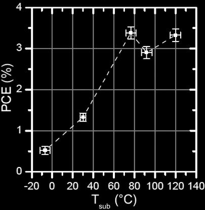
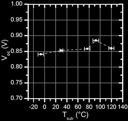
4 current density (ma/cm 2 ) Processing: Substrate Heating FHJ BHJ BHJ heated 0-10 T sub = RT T sub = 88 C substrate heating bias (V) Influence morphology increase FF in BHJ solar cells charge transport (nano-)crystallinity phase separation Slide 4


5 Molecules: Variability! The 2006 K. Schulze C. Uhrich R. Schüppel D. Wynands M. Levichkova H. Ziehlke C. Körner C. Elschner 2013 Material System Slide 5


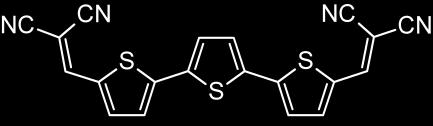
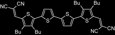
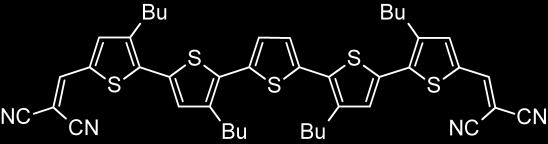
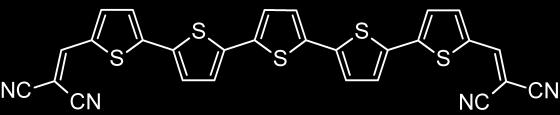
6 The DCVnT-Zoo 3T 4T 5T 6T Me Et Bu ** Slide 6
7 The DCVnT-Zoo Similar properties different performance Slide 7

8 The Starting Point outstanding performance for compound 33 high efficiency of 6.1% reached already for nonoptimized standard device T sub = 90 C Fitzner, Elschner et al., J. Am. Chem. Soc. 2012, 134, Slide 8
9 Thin Film Morphology via GIXRD :C 60 24:C 60 33:C 60 C 60 pristine films mixed films pristine films: highest crystallinity for comp. 15 mixed films: highest crystallinity for comp. 33 ongoing investigations! Fitzner, Elschner et al., J. Am. Chem. Soc. 2012, 134, Slide 9


10 Roadmap for High Efficiency optimize mixing ratio DCV5T/C60: 2:1 optimal substrate temperature: T sub =80 C optimize thickness of the active blend layer: 35-40nm d optimize thickness of window layer: 35-40nm d Slide 10
11 current density j (ma/cm 2 ) 7.2% reached! h EQE (norm.) h EQE voltage V (V) wavelength (nm) certified efficiency at Fraunhofer ISE: h = 7.2% Slide 11

 tandem structures 1.5 1.0 0.")
12 extinction coefficient k Summary molecules and thin film morphology are crucial for high efficiency record efficiency of 7.2% achieved for small molecule organic solar cells Further optimization by increased absorption red-shifted absorption (optical gap at 1.4eV) tandem structures wavelength (nm) Slide 12

13 Acknowlegdments OSOL-group at IAPP Thank You For Your Attention Slide 13
14 IAPP Seminar Dissertation Talk /06/28 Slide 14
15 Thanks to the OSOL group Appendix


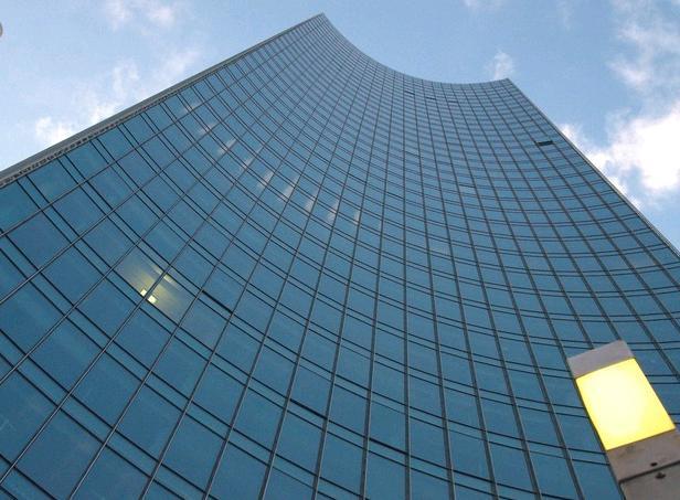
16 Introduction leight-weight flexible cheap colorful transparent superior temperature, angle and low-light performance fotografie/frankfurt-glasfassade.jpg building integration facades mobile applications pictures taken from Slide 16

; heliatek press releases")
17 Solar Cell Efficiency Development 12.0% Sources: NREL ( heliatek press releases Slide 17
 electrode donor acceptor electrode")
 charge transfer charge collection exciton")
18 Charge Carrier Generation Scheme C. Tang, APL 48, 183 (1986) electrode donor acceptor electrode LUMO LUMO 5 HOMO photon absorption 5 4 HOMO (exciton generation) charge transfer charge collection exciton diffusion charge transport Slide 18
19 Organic Solar Cells metal acceptor donor glass + ITO Slide 19
20 Organic Solar Cells metal Why transport layers? electron transport layer (ETL) acceptor set active layer to maximum of optical field (window layers) donor independent of contact material hole transport layer (HTL) avoid charge transport to wrong electrode glass + ITO Slide 20

21 Solar Cell Characterization jv-characteristics P el j V PCE P P out in j MPP V P in MPP V oc FF 1 j sc MPP PCE j sc V P oc in FF Slide 21
 DCV4T Substrate heating Substrate heating")
22 Substrate Heating Review David Wynands: /Franz Selzer: DCV6T-Bu(1,2,5,6) DCV4T Substrate heating Substrate heating Slide 22
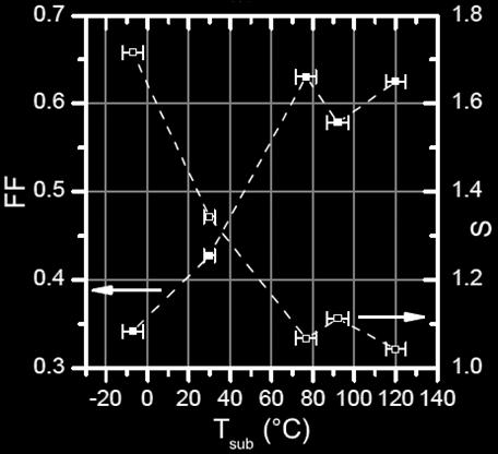
23 Comparison 33 vs 15 Variation of Substrate Temperature j [ma/cm²] RT 80 C 110 C U [V] critical temperature higher for compound 15 improvement up to T sub =80 C above a critical temperature, j sc and V oc are decreased j [ma/cm²] RT 80 C 110 C 140 C U [V] Slide 23
24 EQE Morphological Changes upon Substrate Heating C absorption T sub = 80 C/110 C DCV5T absorption 0.4 T sub = RT 0.2 T sub = 140 C wavelength [nm] Koerner et al., DCV4T, Organic Electronics 13, (2012) Slide 24
: glass together with Chris Elschner, in coop. with Univ.")
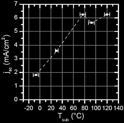
25 Substrate Heating Detailed Investigations surface topography (AFM): increased roughness phase demixing 90 C PL quenching decrease: 30 C DCV4T:C 60 2:1, 20nm C 60 (15nm) excitons are lost structure investigations (GIXRD): glass together with Chris Elschner, in coop. with Univ. of Stanford absorption decrease: p-stacking / molecular orientation changed decrease in j sc Slide 25
26 IAPP Seminar Dissertation Talk /06/28 Slide 26
27 Organic Solar Cells electrode absorber electrode electrode acceptor absorber donor electrode Slide 27


28 Organic Solar Cells LUMO E electrode absorber electrode HOMO very strong exciton binding energy negligible photocurrent! Slide 28

29 absorption Organic Solar Cells x molecules: broad-band narrow-band absorbers solar radiation intensity electrode acceptor donor electrode electrode acceptor photoactive material donor wavelength electrode Slide 29
30 Substrate Heating Review David Wynands: DCV6T-Bu(1,2,5,6) Similar results for DCV6T-Et(2,2,5,5) Substrate heating et. al. DPG AKE Dresden 2013 Slide 30


31 Substrate Heating Solar Cell Characteristics DCV4T x x x x x x x x Au (50nm) ETL (55nm) DCV4T:C 60 2:1, 20nm x x x x x C 60 (15nm) glass + ITO x x x et. al. DPG AKE Dresden 2013 Slide 31

 glass et. al.")
32 Substrate Heating Blend Layer Absorption decrease in absorption j sc directed transmission integrated transmission A 1 R T DCV4T C 60 DCV4T:C 60 2:1, 20nm C 60 (15nm) glass et. al. DPG AKE Dresden 2013 Slide 32
")


33 Substrate Heating Blend Layer Topography (AFM) 30 C 50 C 70 C 90 C AFM-pictures taken by Franz Selzer 90 C 30 C DCV4T:C 60 2:1, 20nm C 60 (15nm) glass et. al. DPG AKE Dresden 2013 Slide 33
34 Substrate Heating Photoluminescence Quenching reference: blends: DCV4T:C 60 2:1, 20nm C 60 (15nm) glass S 1 x CT D/A S 0 donor et. al. DPG AKE Dresden 2013 Slide 34
 glass DCV4T (13.3nm) C 60 (6.7nm) C 60 (15nm) glass et. al.")
35 @ 90 C Substrate Heating Photoluminescence Quenching reference: blends: DCV4T:C 60 2:1, 20nm C 60 (15nm) glass DCV4T (13.3nm) C 60 (6.7nm) C 60 (15nm) glass et. al. DPG AKE Dresden 2013 Slide 35
36 Substrate Heating Structure Investigations (GIXRD) increased crystallinity of DCV4T and C 60 phase : 30 C (blue) 90 C (orange) Change in p-stacking direction (out-of-plane in-plane reflections) = explanation for decrease in absorption (unfavorable molecule orientation to incoming light) et. al. DPG AKE Dresden 2013 Slide 36