Chapter 8. Material-Removal
|
|
|
- Osborn Ross
- 5 years ago
- Views:
Transcription


1 A M A N U F A C T U R I N G P R O C E S S E S Chapter 8. Material-Removal Processes: Cutting Sung-Hoon Ahn School of Mechanical and Aerospace Engineering Seoul National University


 Advanced")
2 Machining ( 기계가공 ) 2 Machining is the broad term used to describe removal of material from a workpiece. Cutting ( 절삭가공 ) Abrasive processes ( 입자가공 ) Advanced machining processes ( 특수기계가공 )


3 High speed machining 3
 Oblique cutting ( 경사절삭 ) Positive Rake")
 ( 여유각 ) (")
4 Chip formation ( 칩형성 ) 4 Orthogonal cutting ( 직교절삭 ) Oblique cutting ( 경사절삭 ) Positive Rake angle ( 경사각 ) Chipaway from the workpiece Negative Rake angle Sturdy ( 경사각 ) ( 여유각 ) ( 전단면 ) ( 전단각 )
5 Orthogonal cutting model 5
6 Shear-angle relationships Merchant model 6 t tc t OD = = where r = < 1 sin φ cos( φ α ) t r cosα tanφ = 1 r sinα C F F R N = F C = F C sinα + F T cosα cos α F sinαα T


7 Strain hardening 7 Machined material (chip) has higher hardness than uncut material due to high strain hardening (shear strain, γ ~20) Vickers indentation test :
8 Chip morphology ( 칩형상 ) (1) 8
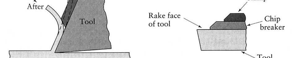
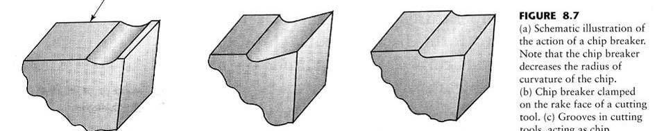
9 Chip morphology ( 칩형상 ) (2) 9 Continuous chips ( 연속형칩 ) High cutting speeds / high rake angles (secondary shear zone) Good for tool life & surface finish (may need chip breaker) Ductile materials with low coefficient of friction Serrated chips ( 톱니형칩 ) Nonhomogeneous / segmented chips Zones of low and high shear strain Ti : sharp decrease of strength and thermal conductivity with increased temperature Built-up Edge chips (BUE, 구성인선 ) High friction coefficient workpiece weld on the tool edge Periodical separation of material bad surface It can be reduced d by increasingi the cutting speed and the rake angle, decreasing the depth of cut, using a tool with asmall tip radius and effective cutting fluid. Discontinuous chips ( 불연속칩 ) Brittle materials (ductile materials with high friction coefficient) : Cast iron, bronze Chatter, vibration


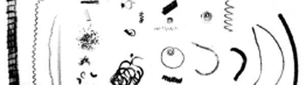

10 Chip morphology ( 칩형상 ) (3) 10 Depending on : cutting speed, temperature, tool angle, friction, vibration
11 Oblique cutting ( 경사절삭 ) 11 Inclination angle ( 기움각 ), i


 w:depth")
12 Turning tool 12 Rate of removal = Vfw Where V f : cutting speed (m/min) : feed (mm/rev) w:depth of cut (mm)

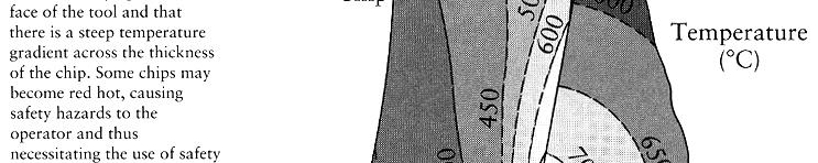


13 Temperature 13
 14")

14 Tool wear ( 공구마멸 ) 14 Flank wear Crater wear Chipping
15 Flank wear 15 F. W. Taylor s tool life equation VT n = C logv = logc nlogt n(hss) = 0.15, V = 50m/min n(tungsten Carbide) = 0.25, V = 70m/min log C
16 Tool condition monitoring 16


17 Surface finish 17
18 Machinability ( 절삭성 ) 18 Surface finish & integrity Tool life Machinability rating: cutting speed per 60min, e.g ft/min (0.5m/s) Force and power requirements Chip control Free-machining steel ( 쾌삭강 ) Steel with : lead, bismuth, sulfur, calcium Easy to machine : aluminum, brass, magnesium Difficult to machine : wrought-copper, titanium, tungsten

")
 Inserts Easy")
19 Cutting-tool materials 19 Carbon steels High Speed Steels (HSS, 고속도강 ) (M and T series) Cast cobalt alloys Carbides ( 초경합금 ) WC (tungsten carbide) TiC (titanium carbide) Inserts Easy to replace tools


20 Coated tool ( 피복공구 ) 20 TiN, TiC, TiCN Al 2 O 3 ( 알루미나 ) Diamond Ion implantation Multiphase
21 Cutting Processes 21
22 Lathe-round shape 22
23 Lathe components 23
24 Drill 24
25 Drilling operations 25
 Slab milling")
 Recommended,")

 Less chatter Production")
26 Milling 26 Depth of Cut (DOC) Width of Cut (WOC) Slab milling ( 평밀링 ) Conventional Milling (up milling, 상향절삭 ) Recommended, clean surface before machine Climb Milling (down milling, 하 향절삭 ) Efficient cut (larger chip) Less chatter Production work WOC DOC WOC DOC
27 Material removal by milling 27 Cutting speed (m/min) V = πdn (D : diameter of cutter(m), N : rotational speed of the cutter(rpm)) Material Removal Rate (MRR) MRR = WOC * DOC * f f = feed rate (mm/min) = n * N * t Cutting Tool - cross section Example V = 50 m/min, t = 0.1 mm/tooth, number of tooth (n)= 2, D = 4 mm, DOC = 0.2, WOC = 3, Cutter RPM (N) = 50000/(πx4) = 3979 f = 2 *3979 * 0.1 = 796 mm/min, MRR = 3* 0.2 * 796 = 4776 mm 3 /min
28 Burr Formation 28
29 FEM Simulation 29 Demo: EMSIM edu/testbeds/emsim/html/index2 shtml
30 Cost Estimation 30
31 Turning conditions 31
32 Drilling conditions 32
33 Milling conditions 33
34 Broaching( 브로칭 ) & Sawing( 톱작업 ) 34


35 Micro Machining System 35 Micro endmills Tip of 127μm endmill Main computer Spindle Positional resolution : 1 μm Tool diameter : 50 μm ~1000 μm High speed : 46,000 RPM Tool material : HSS & TiN coating Work piece : Metal, Polymer, etc Controller X-Y stage Vice Precision stage Microscope
36 Prototyping Size & Time 36 Typical Feature Size 1m 100mm 10mm 1mm Rapid Prototyping Injection Molding 100μm 10μm 1μm Micro Machining MEMS (Days) Typical Prototyping Time
37 DFM - Micro Milling 37 10mm endmill 10μm stage error 0.1% for slot cutting A tip is not exact edge in micro scale 100μm endmill 10μm stage error 10% for slot cutting average Tool Cost ( ) 100,000 TiAlN coating Cost structure of micro machining is different from that of macro machining. Tool cost dominates 10,000 1, Tool diameter (mm)
 + Error Terms (vibration, thermal deformation, etc) <")
 < Result of Total Indicator Reading (TIR) > < Total Indicator Reading (TIR)")
38 Spindle run-out 38 Run-out effect on the final geometry is critical in micro machining Total run-out = TIR (Total Indicator Reading) + Error Terms (vibration, thermal deformation, etc) < Concept of run-out > t ( μm ) Run-ou μm 200 μm Tool length (mm) < Result of Total Indicator Reading (TIR) > < Total Indicator Reading (TIR) Measurement >


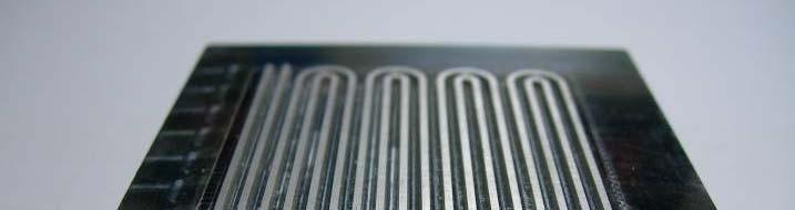
39 Micro walls 39 Barrier ribs Rib width: 60 μm 300 Height: 500 μm Tool: φ200 μm Spindle: 24,000rpm DOC: 25μm Feed rate: 100μm /s Time: 3hr 28min 300 Geometric error: ~ 5 μm (including error of microscope)


40 Micro machined mold mm 1.221mm 1.005mm 0.753mm


41 From Concept to Part 41 Part for UAV/MAV ABS plastic l = 2.9mm, t= 300mm, Pivot D=250 mm Specification CAD design Micro machining Rotor with micro channel Micro injection molded rotor Aluminum mold Total time: 5 days


42 More Meso/Micro Parts 42 Micro corotor Micro molding (ABS) Freeform surface 300mm 3mm Micro pyramid


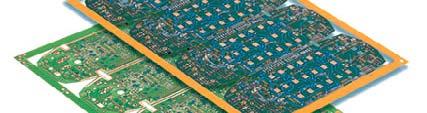

43 Micro Tools 43 Drill PCBs for semiconductor Shape of Micro drill End mill PCBs for cell phone

44 CNC Lathe 44 CNC lathe can achieve multi-functional machining using attached milling turret, sub-spindle, etc. Cutting tool Turret Spindle Chuck Cutting Workpiece Milling tool Turret Cutting + Milling
 45")

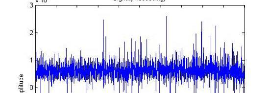
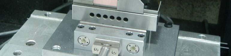
45 Dynamometer ( 공구동력계 ) 45 Measured Signal The whole system configuration Amplifier Cable Dynamometer