Residual Stresses and Distortion in Weldments
|
|
|
- Myra Tate
- 5 years ago
- Views:
Transcription
1 Residual Stresses and Distortion in Weldments By: Aziz Shafiei Residual Stresses 1
2 Causes of Residual Stresses Residual stresses in metal structures occur for many reasons during various manufacturing stages. Residual stresses may be produced in many structural elements, including plate, bar, and sections, during rolling, casting, or forging. They may occur during forming and shaping of metal parts by such processes as shearing, bending, machining, and grinding. 3 of 92 Development of Residual Stresses Thermally induced stresses: (a)during heating; (b)during cooling; (c)residual stresses in weld. 4 of 92 2
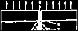
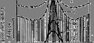
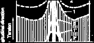
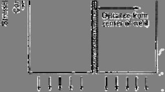
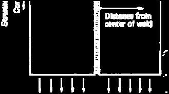
3 Thermal Stresses During Welding 5 of 92 Residual Stresses in a Butt Weld Stress distribution is characterized by two parameters: (1) the maximum stress at weld Region (σ m ) (2) the width of the tension zone of residual stress (b) In weldments made of lowcarbon steel, the maximum residual stress (σ m ) is usually as high as the yield stress of the weld metal. 6 of 92 3

4 Measurement of residual stresses A- Stress-relaxation B- X-ray diffraction C- Stress-sensitive property analysis D- Cracking techniques 7 of 92 Measurement of residual stresses A- Stress-relaxation B- X-ray diffraction C- Stress-sensitive property analysis D- Cracking techniques 8 of 92 4
5 Measurement of residual stresses A- Stress-relaxation B- X-ray diffraction C- Stress-sensitive property analysis D- Cracking techniques 9 of 92 Measurement of residual stresses 10 of 92 5
6 Stress-relaxation Techniques Elastic strain release is measured to determine residual stresses in stressrelaxation analysis. Residual stress is relaxed by removing a piece from the specimen, or by cutting the specimen into pieces. Generally, strain release is measured with electric or mechanical strain gages. 11 of 92 Stress-relaxation Techniques Stress-relaxation techniques are widely used to measure residual stress in weldments, because they produce reliable and quantitative data. However, stress-relaxation techniques are destructive. The specimen must be sectioned either partly or entirely. 12 of 92 6
7 Stress-relaxation Techniques Five techniques for measuring residual stresses, based on stress-relaxation techniques that can be used for weldments, are: or mechanical ain gages Elastic stra Sectioning Technique Using Strain Gages. Mathar-Soete Drilling Technique. The Gunnert Drilling Technique. Rosenthal-Norton Sectioning Technique. Photoelastic Coating-Drilling Technique. PLATE 3D SOLIDS 13 of 92 Stress-relaxation Techniques 14 of 92 7
8 Stress-relaxation Techniques 15 of 92 Stress-relaxation Techniques Mathar-Soete Drilling Technique. 16 of 92 8
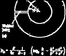
9 Stress-relaxation Techniques Rosenthal-Norton Sectioning Technique. This technique proposed a technique for determining residual stresses in heavy weldments. Two narrow blocks with full thickness of the plate, one parallel to the weld and the other transverse to the weld, are cut from the weld. Residual stress remaining in the narrow blocks is then measured. Formulas have been proposed to estimate residual stresses in the interior of the weldment from strain changes that occur while cutting the narrow blocks and residual stresses that are left in the blocks. 17 of 92 Stress-relaxation Techniques Photoelastic Coating-Drilling Technique. Using this method, a hole is drilled to a certain depth (for instance, equal to the diameter) at the measuring point through the photoelastic coating and a portion of the specimen. Birefringence occurs in areas near the drilled hole if residual stresses exist. By analysis, the birefringence strain release that took place during drilling is determined. Then the residual stresses that existed in the drilled area are calculated. 18 of 92 9
10 X-ray Techniques Elastic strains can be determined nondestructively (without machining or drilling). This is the only technique suitable for measuring residual stresses in applications such as gear teeth and ball bearings. It also is suitable for measuring residual surface stress after machining or grinding. 19 of 92 X-ray Techniques 20 of 92 10
11 Drawbacks X-ray Techniques They are slow processes. Measurements must be made in two directions at each measuring point. Each measurement requires 15 to 30 min of exposure for the film technique. Measurements are not very accurate, particularly with heat treated materials in which atomic structures are distorted. 21 of 92 Hardness Testing Techniques Hardness testing techniques use stress induced changes in hardness. These techniques have not been developed past the laboratory stage, and none has been used with success for measuring residual stresses in weldments. 22 of 92 11
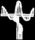
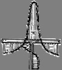
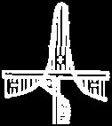
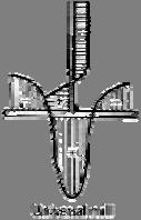
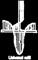
12 Cracking Techniques Residual stresses can be studied by observing cracks cac in specimens e s produced poducedby residual stresses. These cracks may be induced by the presence of hydrogen or stress corrosion. In studying complex structural models that have complicated residual stress distributions, these cracking techniques have been useful. These techniques result in qualitative rather than quantitative data. 23 of 92 Distribution of Residual Stress in Weldments Plug Weld. Welded Shapes and Columns. I Welded Pipe. 24 of 92 12
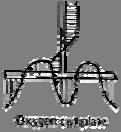
13 Distribution of Residual Stress in Weldments Plug Weld. 25 of 92 Distribution of Residual Stress in Weldments Welded Shapes and Columns. 26 of 92 13


 Welding procedure and sequence (welded on outside")
 28 of 92 14")
14 Distribution of Residual Stress in Weldments Welded Shapes and Columns. 27 of 92 Distribution of Residual Stress in Weldments Welded Pipe. Distribution of residual stresses is affected by: Diameter and wall thickness of the pipe Joint design (square butt, V, X, etc.) Welding procedure and sequence (welded on outside only, welded on both sides, outside first, or welded on both sides, inside first) 28 of 92 14


15 Distribution of Residual Stress in Weldments Welded Pipe. 29 of 92 Residual Stress in Weldments in Various Materials In welding low- carbon steel, the maximum residual stress in the weld is as high as the yield stress of the material. 30 of 92 15

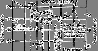
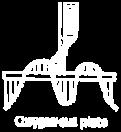
16 Residual Stress in Weldments in Various Materials The magnitude and distribution of residual stress are affected by: Temperature distribution in the weldment. Thermal expansion characteristics of the material. Mechanical properties of the material at room and elevated temperatures. 31 of 92 Residual Stress in Weldments in Various Materials Comparison of some physical properties of steel, aluminum, and titanium 32 of 92 16


17 Residual Stress in Weldments in Various Materials 33 of 92 Residual Stress in Weldments in Various Materials Maximum mechanical strains observed at locations 1 in. from weld line (μin./in.) versus yield strength th (ksi) of the base plate. 34 of 92 17
18 Residual Stress in Weldments in Various Materials Welds in High-Strength Steels. Welds in Aluminum Alloys. Welds in Titanium Alloys. 35 of 92 Residual Stress in Weldments in Various Materials Welds in High-Strength Steels. Are peak values of residual stresses as high as the yield stresses of the weld metal and base metal? How wide are the areas with high tensile residual stresses? 36 of 92 18
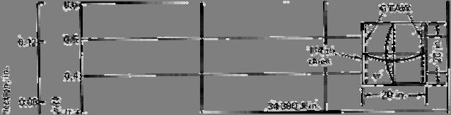
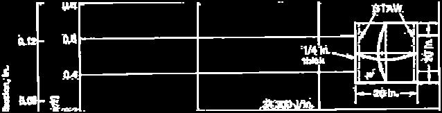
19 Residual Stress in Weldments in Various Materials Welds in High-Strength Steels. Distribution of longitudinal residual stresses in a butt weld in high-strength steel. 37 of 92 Residual Stress in Weldments in Various Materials Welds in Aluminum Alloys. Distribution of yield strength and longitudinal residual stresses in a welded 5456-H321 plate 36 in. wide and 1/2 in. thick. 38 of 92 19

,")


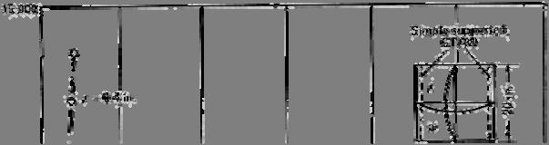
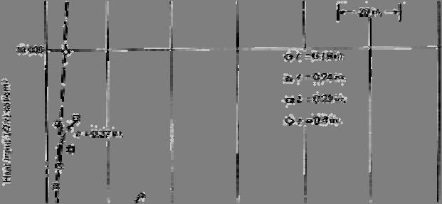
20 Residual Stress in Weldments in Various Materials Welds in Titanium Alloys. Distribution of residual stresses in weldment of Ti-6Al-2Nb-1Ta-1Mo alloy made by gas metal arc welding (GMAW), using Ti-6A1-2Nb-1Ta-0.8Mo filler wire. 39 of 92 Effects of Specimen Size on Residual Stress When measuring residual stress in a weldment, welded specimens must be large enough to contain residual stresses as high as those that exist in actual structures. Effect of Specimen Length. Effect of Specimen Width. 40 of 92 20
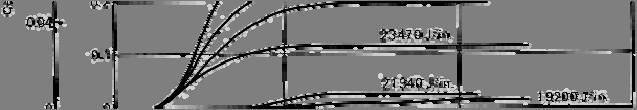
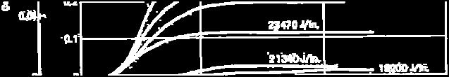
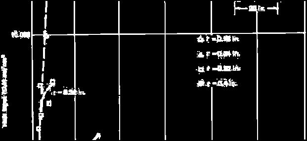
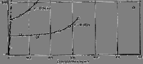
21 Effects of Specimen Size on Residual Stress Effect of Specimen Length. Longitudinal residual stress values must be zero at both ends of the weld, while high tensile stresses exist in the central region. The peak stress in the central region increases with increasing weld length. 41 of 92 Effects of Specimen Size on Residual Stress Effect of Specimen Length. Longitudinal residual stress values must be zero at both ends of the weld, while high tensile stresses exist in the central region. The peak stress in the central region increases with increasing weld length. Welds longer than 18 in. are needed to produce high tensile stresses in the longitudinal direction. 42 of 92 21
22 Effects of Specimen Size on Residual Stress Effect of Specimen Length. Longitudinal residual stress values must be zero at both ends of the weld, while high tensile stresses exist in the central region. The peak stress in the central region increases with increasing weld length. Welds longer than 18 in. are needed to produce high tensile stresses in the longitudinal direction. In welds longer than 18 in., longitudinal residual stresses in the central region became uniform. 43 of 92 Distortion 22
23 Distortion in Weldments During heating and cooling in the welding cycle, thermal strains accurse in the weld metal and basemetal regions near the weld. The strains produced during heating are accompanied by plastic upsetting. The stresses resulting from these strains combine and react to produce internal forces that cause bending, buckling, and rotation. It is these displacements that are called distortion. 45 of 92 Fundamental Types of Distortion Transverse shrinkage perpendicular to the weld line. Longitudinal shrinkage parallel to the weld line. Angular distortion (rotation around the weld line). 46 of 92 23
24 Distortion in welded structures Slide 7 Slide 7 47 of 92 Distortion in Weldments 48 of 92 24
25 Transverse Shrinkage of Butt Welds Major factors causing non-uniform transverse shrinkage in butt welds are: Rotational Distortion. Joint Restraint. Slide of 92 Transverse Shrinkage of Butt Welds Major factors causing non-uniform transverse shrinkage in butt welds are: Rotational Distortion. The rotational distortion is affected by welding heat input and the location of tack welds. 50 of 92 25


26 Formulas for Transverse Shrinkage Spraragen and Ettinger. S is transverse shrinkage, in. A, is cross-sectional area of weld, in. 2 t is thickness of plates, in. d is free distance or root opening, in. 51 of 92 Formulas for Transverse Shrinkage Capel. Δl is transverse shrinkage, in. s is thickness of layer of weld metal, in. u is welding speed, in./min W is electric power of welding arc, W p 60 V-groove, without a root gap GTAW SMAW SMAW 52 of 92 26
27 Formulas for Transverse Shrinkage Capel. 53 of 92 Mechanisms of Transverse Shrinkage The major portion of transverse shrinkage of a butt weld is due to contraction of the base plate. Shrinkage of the weld metal is only about 10% of the actual shrinkage. 54 of 92 27


28 Mechanisms of Transverse Shrinkage δ s : Thermal expansion of the base metal at t = t metal at t = t s δ: Additional thermal deformation of the base metal caused in AA' at t > t s S w : Thermal contraction of the weld metal at t > t s 55 of 92 Mechanisms of Transverse Shrinkage 56 of 92 28

29 Transverse Shrinkage During multipass Welding 57 of 92 Transverse Shrinkage During multipass Welding Three methods to reduce transverse shrinkage: 58 of 92 29


30 Transverse Shrinkage During multipass Welding The effects of various factors on transverse shrinkage, including: Greatest Effect Root opening Joint design Type and size of electrodes 0 Heat input 59 of 92 Effect of Welding Sequence on Transverse Shrinkage 60 of 92 30


31 Effect of Restraint on Transverse Shrinkage 61 of 92 Effect of Restraint on Transverse Shrinkage 62 of 92 31


32 Effect of Restraint on Transverse Shrinkage Slit-type specimen. 63 of 92 Effect of Restraint on Transverse Shrinkage Circular-ring type specimen. 64 of 92 32


33 Longitudinal Shrinkage of Butt Welds The amount of longitudinal shrinkage in a butt weld is on the order of I/I000 of the weld length, much less than the transverse shrinkage. I is the welding current, A L is the length of weld, in. t is the plate thickness,in. Slide of 92 Longitudinal Shrinkage of Fillet Welds As plate width and thickness increase, restraint is more effective. Therefore, total cross section of the welded plate in the transverse section is called the "resisting cross section". For A p to A w is less than 20: 66 of 92 33
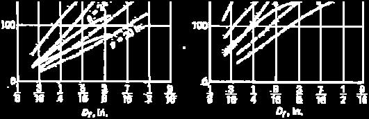
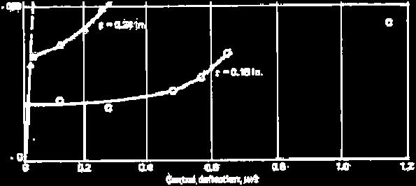
34 Angular Change in Fillet Welds Φ<Φ 0 67 of 92 Angular Change in Fillet Welds Φ<Φ 0 Rigidity idit of the bottom plate: Angular rigidity coefficient: 68 of 92 34
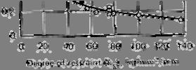
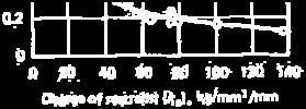
35 Angular Change in Fillet Welds Values of angular rigidity coefficient C for low-carbon steel 69 of 92 Angular Change in Fillet Welds 70 of 92 35
36 Angular Change in Fillet Welds 71 of 92 Angular Change in Fillet Welds Values of angular rigidity coefficient C for 5086-H32 aluminum alloy 5086-H32 was gas metal arc welded with alloy 5356 filler wire. 72 of 92 36


37 Angular Change in Fillet Welds 73 of 92 Angular Change in Fillet Welds 74 of 92 37


38 Angular Change in Fillet Welds 75 of 92 Bending Distortion Produced by Longitudinal Shrinkage T-beams were fabricated by fillet welding a web plate 4 or 6 in. hightoaflangeplate4in.wide. The 5052-H32 alloy plates were 0.5 in. thick and 48 in. long; they were welded by GMAW using 4043 and 2319 filler wires. 76 of 92 38

39 Buckling Distortion 77 of 92 Buckling Distortion 78 of 92 39


40 Comparison of Distortion in Aluminum and Steel Weldments The value of thermal conductivity of aluminum is about five times that of steel. The coefficient of linear thermal expansion of aluminum is about two times that of steel. The value of Young's modulus of aluminum is about one third that of steel. 79 of 92 Comparison of Distortion in Aluminum and Steel Weldments Transverse Shrinkage of a Butt Weld. 80 of 92 40


41 Comparison of Distortion in Aluminum and Steel Weldments Angular Change of a Fillet Weld. 81 of 92 Comparison of Distortion in Aluminum and Steel Weldments Longitudinal Distortion. 82 of 92 41
42 Effects of Residual Stresses and Distortion on Service Behavior of Welded Structures Changes of Residual Stresses in Weldments Subjected to Tensile Loading The stress distribution across the weld becomes more even as the level of applied stress increases. As the level of loading increases, theresidual stress distribution after unloading becomes more even. As the level of applied stress increases, the effect of residual stress decreases. 84 of 92 42


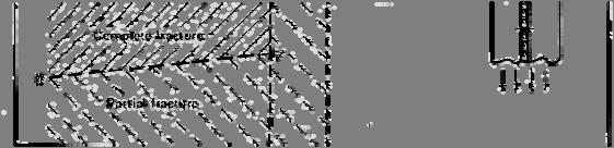
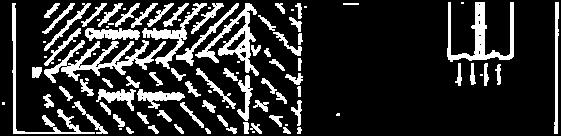
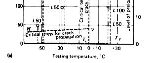
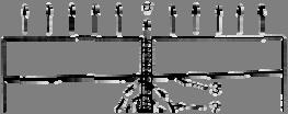
43 Effects of Residual Stresses on Brittle Fractures of Welded Structures 85 of 92 Effect of Stress-Relieving Treatments on Brittle Fracture of Weldments Mechanical Stress Reliving 86 of 92 43

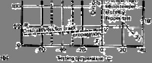
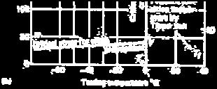
44 Effect of Stress-Relieving Treatments on Brittle Fracture of Weldments Thermal Stress Reliving 87 of 92 Effects of Residual Stresses on Fatigue Fracture of Welded Structures 88 of 92 44

45 Buckling Under Compressive Loading 89 of 92 Buckling Under Compressive Loading 90 of 92 45


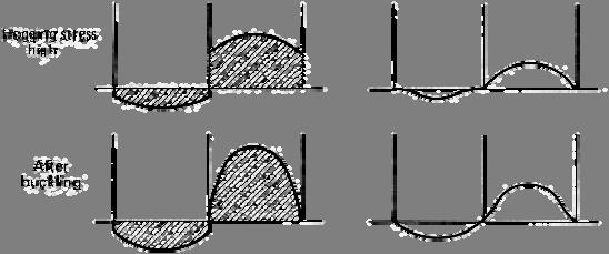
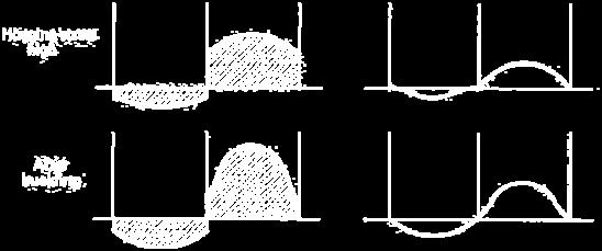
46 Buckling Under Compressive Loading Combined Effects of Residual Stresses and Distortion. 91 of 92 Buckling Under Compressive Loading Combined Effects of Residual Stresses and Distortion. 92 of 92 46