Hail University College of Engineering Department of Mechanical Engineering. Joining Processes and Equipment. Fusion-Welding.
|
|
|
- Beatrice Lyons
- 5 years ago
- Views:
Transcription
1 Hail University College of Engineering Department of Mechanical Engineering Joining Processes and Equipment Fusion-Welding Ch 30

2 Joining is an all-inclusive term covering processes such as welding, brazing, soldering, adhesive bonding, and mechanical fastening. Various parts in a typical automobile
 A tubular part fabricated by joining individual components.")
3 These processes are an essential and important aspect of manufacturing and assembly operations, for one or more of the following reasons: 1-Even a relatively simple product may be impossible to manufacture as a single piece. Consider, for example, the tubular construction Examples of parts utilizing joining processes. (a) A tubular part fabricated by joining individual components. This product cannot be manufactured in one piece by any of the methods described in the previous chapters if it consists of thin-walled, large-diameter, tubular-shaped long arms. (b) A drill bit with a carbide cutting insert brazed to a steel shank an example of a part in which two materials need to be joined for performance reasons. (c) Spot welding of automobile bodies.
4 Joining important aspect of manufacturing and assembly operations 2.The product, such as a cooking pot with a handle, is easier and more economical to manufacture as individual components, which are then assembled into a product 3.Products such as hair dryers, appliances, and automobile engines need to be designed to be able to be taken apart for maintenance or replacement of their parts. 4. Different properties may be desirable for functional purposes of the product. For example, surfaces subjected to friction, wear, corrosion, or environmental attack generally require characteristics that differ significantly from those of the component's bulk. Examples are (a) masonry drills with carbide cutting tips brazed to the shank of a drill 5.Transporting the product in individual components and assembling them later may be easier and less costly than transporting the completed item.

5 Although there are different ways of categorizing the wide variety of available joining processes, we will follow the classification by the American Welding Society (AWS)

6 Joining processes joining processes fall into three major categories Welding, Adhesive bonding and Mechanical fastening Welding processes, in turn, are generally classified into three basic categories: Fusion welding,solid-state welding and Brazing and soldering Comparison of Various Joining Methods

7 Fusion welding is defined as the melting together and coalescing of materials by means of heat, usually supplied by chemical or electrical means; filler metals mayor may not be used. Fusion welding is composed of consumable-and non consumable electrode arc welding and high-energy-beam welding processes. In solid-state welding, joining takes place without fusion; consequently, there is no liquid (molten) phase in the joint. The basic processes in this category are diffusion bonding and cold, ultrasonic, friction, resistance, and explosion welding. Brazing uses filler metals and involves lower temperatures than welding. Soldering uses similar filler metals (solders) and involves even lower temperatures. Examples of joints that can be made through the various joining processes
8 Joining processes Adhesive bonding has unique applications that require strength, sealing, thermal and electrical insulating, vibration damping, and resistance to corrosion between dissimilar metals. Mechanical fastening involves traditional methods of using various fasteners, especially bolts, nuts, and rivets. The joining of plastics can be accomplished by adhesive bonding, fusion by various external or internal heat sources, and mechanical fastening.
9 Fusion-Welding Processes The Fusion welding processes involve the partial melting and fusion between two members to be joined. Here, fusion welding is defined as melting together and coalescing materials by means of heat Filler metals, which are metals added to the weld area during welding, also may be used. Fusion welds made without the use of filler metals are known as autogenous welds.
10 Fusion-Welding Processes General Characteristics of Fusion-welding Processes
11 Oxyfuel-gas Welding Oxyfuel-gas welding (OFW) is a general term used to describe any welding process that uses a fuel gas combined with oxygen to produce a flame. The flame is the source of the heat that is used to melt the metals at the joint. The most common gas welding process uses acetylene; the process is known as oxyacetylene-gas welding (OAW) and is typically used for structural metal fabrication and repair work. OAW utilizes the heat generated by the combustion of acetylene gas (C 2 H 2 ) in a mixture with oxygen. The heat is generated in accordance with a pair of chemical reactions. The primary combustion process, which occurs in the inner core of the flame involves the following reaction: This reaction dissociates the acetylene into carbon monoxide and hydrogen and produces about one-third of the total heat generated in the flame.
12 Oxyfuel-gas Welding The secondary combustion process is This reaction consists of the further burning of both the hydrogen and the carbon monoxide and produces about two-thirds of the total heat. Note that the reaction also produces water vapor. The temperatures developed in the flame can reach 3300 C. Flame Types The proportion of acetylene and oxygen in the gas mixture is an important factor in oxyfuel-gas welding Neutral, At a ratio of 1:1 oxidizing flame, With a greater oxygen supply reducing, or carburizing, flame, flame having excess acetylene Other fuel gases (such as hydrogen and. methylacetylene propadiene) also can be used in oxyfuel-gas welding. However, the temperatures developed by these gases are lower than those produced by acetylene. Hence, they are used for welding (a) metals with low melting points (such as lead)
13 Three basic types of oxyacetylene flames used in oxyfuel gas welding and cutting operations: (a) neutral flame; (b) oxidizing flame; (c) carburizing, or reducing, flame. The gas mixture in (a) is basically equal volumes of oxygen and acetylene. (d) The principle of the oxyfuel gas welding process.

14 Filler Metals Filler metals are used to supply additional metal to the weld zone during welding. They are available as filler rods or wire and may be bare or coated with flux. The purpose of the flux is to retard oxidation of the surfaces of the parts being welded by generating a gaseous shield around the weld zone. The flux also helps to dissolve and remove oxides and other substances from the weld zone, thus contributing to the formation of a stronger joint. The slag developed (compounds of oxides, fluxes, and electrodecoating materials) protects the molten puddle of metal against oxidation as it cools.
15 Welding Practice and Equipment of oxyfuel-gas welding Oxyfuel-gas welding can be used with most ferrous and nonferrous metals for almost any workpiece thickness, but the relatively low heat input limits the process to thicknesses of less than 6 mm. Small joints made by this process may consist of a single-weld bead. Deep-V groove joints are made in multiple passes. Cleaning the surface of each weld bead prior to depositing a second layer is important for joint strength and in avoiding defects. The equipment for oxyfuel-gas welding consists basically of a welding torch connected by hoses to high-pressure gas cylinders and equipped with pressure gages and regulators The equipment for oxyuel-gas welding consists basically of a welding torch connected by hoses to high-pressure gas cylinders and equipped with pressure gages and regulators. The use of safety equipment (such as goggles with shaded lenses, face shields, gloves, and protective clothing) is essential. Proper connection of the hoses to the cylinders is an important factor in safety. Oxygen and acetylene cylinders have different threads, so the hoses cannot be connected to the wrong cylinders.
16 (a) General view of, and (b) cross section of, a torch used in oxyacetylene welding. The acetylene valve is opened first. The gas is lit with a spark lighter or a pilot light. Then the oxygen valve is opened and the flame adjusted. (c) Basic equipment used in oxyfuel gas welding. To ensure correct connections, all threads on acetylene fittings are left handed, whereas those for oxygen are right handed. Oxygen regulators usually are painted green and acetylene regulators red. oxyfuel-gas welding

17 Pressure-gas Welding In this method, the welding of two components starts with the heating of the interface by means of a torch using (typically) an oxyacetylenegas mixture After the interface begins to melt, the torch is withdrawn. A force is applied to press the two components together and is maintained until the interface solidifies. Note the formation of a flash due to the upsetting of the joined ends of the two components. Schematic illustration of the pressure-gas welding process: (a) before and (b) after. Note the formation of a flash at the joint; later the flash can be trimmed off.
18 3. Arc-welding Processes: No consumable Electrode the heat required is obtained from electrical energy. The process involves either a consumable or a nonconsumable electrode. An AC or a DC power supply produces an arc between the tip of the electrode and the workpiece to be welded. The arc generates temperatures of about 30,000 C, which are much higher than those developed in oxyfuel-gas welding. (a) The gas tungsten-arc welding process, formerly known as TIG (for tungsten inert-gas) welding. (b) Equipment for gas tungsten-arc welding operations.
19 Arc-welding Processes: No consumable Electrode In no consumable-electrode welding processes, the electrode is typically a tungsten electrode. Because of the high temperatures involved, an externally supplied shielding gas is necessary to prevent oxidation of the weld zone The selection of current levels depends on such factors as the type of electrode, metals to be welded, and depth and width of the weld zone.

20 Arc-welding Processes: No consumable Electrode In straight polarity-also known as direct-current electrode negative (DCEN)the workpiece is positive (anode), and the electrode is negative (cathode). DCEN generally produces welds that are narrow and deep In reverse polarity-also known as direct-current electrode positive (DCEP}- tbe workpiece is negative and the electrode is positive. Weld penetration is less, and the weld zone is shallower and wider DCEP is preferred for sheet metals and for joints with very wide gaps. In the AC current method, the arc pulsates rapidly. This method is suitable for welding thick sections and for using large-diameter electrodes at maximum currents The effect of polarity and current type on weld beads: (a) DC current with straight polarity; (b) DC current with reverse polarity; (c) AC current.
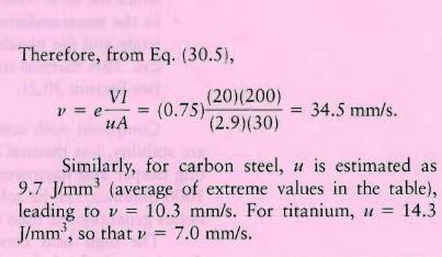
21 Heat Transfer in Arc Welding The heat input in arc welding is given by the equation where H is the heat input (J or BTU), l is the weld length, V is the voltage applied, I is the current (amperes), and j/ is the welding speed. The term e is the efficiency of the DC (+) process and varies from around 75% for shielded metal-arc welding to 90% for gas metal-arc welding and submerged-arc welding. The heat input of melts a certain volume of material, usually the electrode or filler metal, and can also be expressed as where u is the specific energy required for melting, V m is the volume of material melted so the expression of the welding speed:

22 Heat Transfer in Arc Welding
23
24
25 Gas Tungsten-arc Welding In gas tungsten-arc welding (GTAW), formerly known as TIG (for "tungsten inert gas") welding, the filler metal is supplied from a filler wire Because the tungsten electrode is not consumed in this operation, a constant and stable arc gap is maintained at a constant current level. The filler metals are similar to the metals to be welded, and flux is not used. The shielding gas is usually argon or helium (or a mixture of the two). Welding with GTAW may be done without filler metals-for example, in the welding of close-fit joints. Plasma-arc Welding In plasma-arc welding (PAW), concentrated plasma arc is produced and directed towards the weld area. The arc is stable and reaches temperatures as high as 33,000 C, A plasma is an ionized hot gas composed of nearly equal numbers of electrons and ions. The plasma is initiated between the tungsten electrode and the orifice by a low-current pilot arc. What makes plasma-arc welding unlike other processes is that the plasma arc is concentrated because it is forced through a relatively small orifice.

26 There are two methods of plasma-arc welding transferred-arc method nontransferred method Compared with other arc-welding processes, plasma-arc welding has better arc stability, less thermal distortion, and higher energy concentration, thus permitting deeper and. narrower welds. In addition, higher welding speeds, from 120 to 1000 mm/min, can be achieved. Two types of plasma-arc welding processes: (a) transferred and (b) nontransferred. Deep and narrow welds can be made by these processes at high welding speeds.
27 Atomic-hydrogen Welding. In atomic-hydrogen welding (AHW), an arc is generated between two tungsten electrodes in a shielding atmosphere of hydrogen gas. The arc is maintained independently of the workpiece or parts being welded. The hydrogen gas normally is diatomic (H 2 ), but where the temperatures are over 6,000 C near the arc, the hydrogen breaks down into its atomic form, simultaneously absorbing a large amount of heat from the arc. When the hydrogen strikes the cold surface of the workpieces to be joined, it recombines into its diatomic form and rapidly releases the stored heat. The energy in AHW can be varied easily by changing the distance between the arc stream and the workpiece surface.
 is one of the oldest, simplest, and most versatile joining processes.")
28 30.4 Arc-welding Processes: Consumable Electrode There are several consumable-electrode arc-welding processes. 1. Shielded Metal-arc Welding 2. Gas Metal-arc Welding 1. Shielded Metal-arc Welding Shielded metal-arc welding (SMAW) is one of the oldest, simplest, and most versatile joining processes. About 50% of all industrial and maintenance welding currently is performed by this process. Schematic illustration of the shielded metal-arc welding process. About 50% of all large-scale industrial-welding operations use this process.
29 1. Shielded Metal-arc Welding The electrodes are in the shapes of thin, long rods (hence, this process also is known as stick welding) that are held manually. The heat generated melts a portion of the electrode tip, its coating, and the base metal in the immediate arc area. The molten metal consists of a mixture of the base metal (the workpiece), the electrode metal, and substances from the coating on the electrode The electrode coating deoxidizes the weld area and provides a shielding gas to protect it from oxygen in the environment. The current, which may be DC or AC, usually ranges from 50 to 300 A. For sheet-metal we ding, DC is preferred because of the steady arc it produces. Power requirements generally are less than 10 kw. The SMAW process has the advantages of being relatively simple, versatile, and requiring a smaller variety of electrodes. The equipment consists of a power supply, cables, and an electrode holder. The SMAW process commonly is used in general construction, shipbuilding, pipelines, and maintenance work.

30 Shielded Metal-arc Welding SMAW is best suited for workpiece thicknesses of 3 to 19 mm, although this range can be extended easily by skilled operators using multiple-pass techniques. The multiple-pass approach requires that the slag be removed after each weld bead. Unless removed completely, the solidified slag can cause severe corrosion of the weld area and lead to failure of the weld, but it also prevents the fusion of weld layers and, therefore, compromises the weld strength. A deep weld showing the buildup sequence of eight individual weld beads.
31 Gas Metal-arc Welding (MIG) In gas metal-arc welding (GMAW), formerly called metal inert-gas (MIG) welding, the weld area is shielded by an effectively inert atmosphere of argon, helium, carbon dioxide, or various other gas mixtures (a) Schematic illustration of the gas metal-arc welding process, formerly known as MIG (for metal inert-gas) welding. (b) Basic equipment used in gas metal-arc welding operations.
32 Shielded Metal-arc Welding The consumable bare wire is fed automatically through a nozzle into the weld arc by a wire-feed drive motor In addition to using inert shielding gases, deoxidizers usually are present in the electrode metal itself in order to prevent oxidation of the molten-weld puddle. Multiple-weld layers can be deposited at the joint. Metal can be transferred by three methods in the GMAW process: 1. In spray transfer, small, molten metal droplets from the electrode are transferred to the weld area at a rate of several hundred droplets per second- High DC currents and voltages and. large-diameter electrodes are used with argon or an argon-rich gas mixture as the shielding gas. 2. In globular transfer, carbon-dioxide-rich gases are utilized, and globules are propelled by the forces of the electric-arc transfer of the metal, resulting in considerable spatter. Heavier sections commonly are joined by this method. 3.In short circuiting, the metal is transferred in individual droplets (more than 50 per second) as the electrode tip touches the molten weld metal and shortcircuits. Low currents and voltages are utilized with carbon-dioxide-rich gases and electrodes made of small-diameter wire. The power required is
33 Shielded Metal-arc Welding The temperatures generated in GMAW are relatively low; consequently, this method is suitable only for thin sheets and sections of less than 6 mm; otherwise incomplete fusion may occur. The operation, which is easy to perform, is commonly used for welding ferrous metals in thin sections. Pulsed-arc systems are used for thin ferrous and nonferrous metals. The GMAW process is suitable for welding most ferrous and nonferrous metals and is used extensively in the metal-fabrication industry. Because of the relatively simple nature of the process, the training of operators is easy. The process is versatile, rapid, and economical, and welding productivity is double that of the SMAW process.
34 30.5 Electrodes for Arc Welding Electrodes for consumable arc-welding processes are classified according to the following properties: Strength of the deposited weld metal Current (AC or DC) Type of coating. Electrodes are identified by numbers and letters or by color code if the numbers and letters are too small to imprint. Typical coated-electrode dimensions are in the range from 150 to 460 mm in length and 1.5 to 8 mm in diameter.
35 Electrodes for Arc Welding Specifications for electrodes and filler metals (including dimensional tolerances, quality control procedures, and processes) are published by the American Welding Society (AWS) and the American National Standards Institute (ANSI). Some specifications appear in the Aerospace Materials Specifications (AMS) by the Society of Automotive Engineers (SAE). Electrodes are sold by weight and are available in a wide variety of sizes and specifications. Criteria for selection and recommendations for electrodes for a particular metal and its application can be found in supplier literature and in the various handbooks and references Electrode Coatings Electrodes are coated with claylike materials that include silicate binders and powdered materials, such as oxides, carbonates, fluorides, metal alloys, cotton cellulose, and wood flour. The coating, which is brittle and takes part in complex interactions during welding, has the following basic functions: Stabilize the arc. Generate gases to act as a shield against the surrounding Control the rate at which the electrode melts. Act as a flux to protect the weld against the formation of oxides, nitrides, Add alloying elements to the weld zone to enhance the properties of the joint among these elements are deoxidizers to prevent the weld from becoming brittle.

36 Laser-beam Welding Laser-beam welding (LBW) utilizes a high-power laser beam as the source of heat, to produce a fusion weld. Because the beam can be focused onto a very small area, it has high energy density and deep-penetrating capability. The beam can be directed, shaped, and focused precisely on the workpiece. Consequently, this process is suitable particularly for welding deep and narrow joints with depthto-width ratios typically ranging from 4 to 10. Laser-beam welding has become extremely popular and is used in most industries. In the automotive industry, welding transmission components are the most widespread application. Among numerous other applications is the welding of thin parts for electronic components. The laser beam may be pulsed (in milliseconds) with power levels up to 100 kw for applications such as the spot welding of thin materials. Continuous multi-kw Comparison of the sizes of weld beads: (a) laser-beam or electron-beam welding and (b) tungsten arc welding. Source: Courtesy of American Welding Society.
37 30.9 The Weld Joint, Quality, and Testing Three distinct zones can be identified in a typical weld joint 1. Base metal 2. Heat-affected zone 3. Weld metal. The metallurgy and properties of the second and third zones depend strongly on the type of metals joined, the particular joining process, the filler metals used (if any), and welding process variables Characteristics of a typical fusion-weld zone in oxyfuel gas and arc welding.
38 The Weld Joint, Quality, and Testing A joint produced without a filler metal is called autogenous, and its weld zone is composed of the resolidified base metal. A joint made with a filler metal has a central zone called the weld metal and is composed of a mixture of the base and the filler metals. Solidification of the Weld Metal After the application of heat and the introduction of the filler metal (if any) into the weld zone, the weld joint is allowed to cool to ambient temperature. The solidification process is similar to that in casting and begins with the formation of columnar (dendritic) grains. These grains are relatively long and form parallel to the heat flow. Because metals are much better heat conductors than the surrounding air, the grains lie parallel to the plane of the two components being welded.in contrast, the grains in a shallow weld

39 Solidification of the Weld Metal The resulting structure depends on the particular alloy, its composition, and the thermal cycling to which the joint is subjected. For example, cooling rates may be controlled and reduced by preheating the general weld area prior to welding. Preheating is important, particularly for metals having high thermal conductivity, such as aluminum and copper. Without preheating, the heat produced during welding dissipates rapidly through the rest of the parts being joined. Grain structure in (a) a deep weld and (b) a shallow weld. Note that the grains in the solidified weld metal are perpendicular to their interface with the base metal. (c) Weld bead on a cold-rolled nickel strip produced by a laser beam. (d) Microhardness (HV) profile across a weld bead.
40 Heat-affected Zone. The heat-affected zone (HAZ) is within the base metal itself. It has a microstructure Indifferent from that of the base metal prior to welding because it has been temporarily subjected to elevated temperatures during welding. The portions of the base metal that are far enough away from the heat source do not undergo any microstructural changes during welding because of the far lower temperature to which they are subjected. The properties and microstructure of the HAZ depend on (a) the rate of heat input and cooling and (b) the temperature to which this zone was raised. In addition to metallurgical factors (such as the original grain size, grain orientation, and degree of prior cold. work), physical properties (such as the specific heat and thermal conductivity of the metals) influence the size and characteristics of the HAZ. Weld Quality The major discontinuities that affect weld quality are described here. Porosity. Slag Inclusions. Incomplete Fusion and Penetration

41 Incomplete fusion produces poor weld beads, A better weld can be obtained by the use of the following practices: Raising the temperature of the base metal. Cleaning the weld area before welding. Weld Incomplete fusion Weld Base metal Examples of various discontinuities in fusion welds. Incomplete penetration occurs when the depth of the welded joint is insufficient. Penetration can be improved by the following practices: Increasing the heat input. Reducing the travel speed during the welding. Modifying the joint design. Ensuring that the surfaces to be joined fit each other properly.

42 Weld Profile Weld profile is important not only because of its effects on the strength and appearance of the weld, but also because it can indicate incomplete fusion or the presence of slag inclusions in multiple-layer welds. Examples of various defects in fusion welds.

43 Cracks Cracks may occur in various locations and directions in the weld area. Typical types of cracks are longitudinal, transverse, crater, underbead, and toe cracks Types of cracks developed in welded joints. The cracks are caused by thermal stresses, similar to the development of hot tears in castings,

44 Cracks generally result from a combination of the following factors: 1.Temperature gradients that cause thermal stresses in the weld zone. 2.Variations in the composition of the weld zone that cause different rates of contraction during cooling. 3.Embrittlement of grain boundaries caused by the segregation of such elements as sulfur to the grain boundaries and occurring when the solid-liquid boundary moves when the weld metal begins to solidify. 4. Hydrogen embrittlement 5.Inability of the weld metal to contract during cooling Crack in a weld bead. The two welded components were not allowed to contract freely after the weld was completed..

45 The basic crack-prevention measures in welding are the following: 1.Modify the joint design to minimize stresses developed from shrinkage during cooling. 2. Change the parameters, procedures, and sequence of the welding operation. 3. Preheat the components to be welded. 4. Avoid rapid cooling of the welded components Distortion of parts after welding. Distortion is caused by differential thermal expansion and contraction of different regions of the welded assembly.
46 Testing of Welds As in all manufacturing processes, the quality of a welded joint is established by testing. Several standardized tests and test procedures have been established. They are available from many organizations, such as the American Society for Testing and Materials (ASTM), the American Welding Society (AWS), the American Society of Mechanical Engineers (ASME), the American Society of Civil Engineers (ASCE), and various federal agencies. Welded joints may be tested either destructively or nondestructively Destructive Testing Techniques: Tension test Tension-shear test Bend test Fracture toughness test Nondestructive Testing Techniques Visual Radiographic (X-rays) Magnetic-particle Liquid-penetrant Ultrasonic.
47 Testing of Welds (a) Specimens for longitudinal tension-shear testing and for transfer tension-shear testing. (b) Wraparound bend-test method. (c) Three-point transverse bending of welded specimens.