A Scanning Probe Investigation of Inter-Granular Corrosion in Sensitised Stainless Steel Nuclear Fuel Cladding
|
|
|
- Gwendoline Lane
- 5 years ago
- Views:
Transcription
 Professor Geraint Williams (Swansea University) Dr.")
1 A Scanning Probe Investigation of Inter-Granular Corrosion in Sensitised Stainless Steel Nuclear Fuel Cladding Ronald Clark (Final year PhD.) Professor Geraint Williams (Swansea University) Dr. Steve Walters (National Nuclear Laboratory) M2A EngD Seminar Great Hall, Swansea University Bay Campus 5th April 2016 Hinkley Point B Advanced Gas-cooled Reactor, EDF Energy
2 AGR Fuel Cladding Austenitic (γ-phase) stainless steel (SS) fuel cladding is used in British Advanced Gascooled Reactors (AGR) High-nickel, high-chromium, niobium-stabilised alloy specially designed for the AGR programme Typical composition of AGR cladding shown below [1] Cr Ni Mn Si Nb C N Fe <10 x wt%. C Balance [1] C. Taylor, The Formation of Sensitised Microstructures during the Irradiation of AGR Fuel Cladding, pp Symposium on Radiation-Induced Sensitisation of Stainless Steels,
3 AGR Fuel Cladding Vast majority of fuel is unaffected by radiation during use Small proportion ~22 % are potentially affected by radiation, and may have become sensitised [2] We can induce sensitisation by heat treatments (thermal sensitisation method) This represents a challenge, given the relative long storage life of cladding within cooling ponds, pending final geological disposal. Some estimates envisage durations of 80 years in long-term storage. [2] Martin Scott Adam. The Characteristics of Failed AGR Fuel. NNL Internal report, NNL (10) 1(8):1 39,

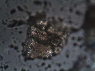
 XRD Characterisation Hematite iron")
4 Thermal Treatment Heat treatment 1150 ⁰C 30 minutes 600 ⁰C 2 weeks SS is sensitised In aqueous environments may be susceptible to Intergranular Corrosion (IGC) XRD Characterisation Hematite iron oxide present


5 Intergranular Corrosion IGC is a type of corrosion affecting grain boundaries Attack is focussed on Cr-depleted zones Example given: Sensitised 310SS exposed to 10 wt% FeCl 3, Crevice sites, 24 Hr 5


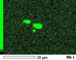
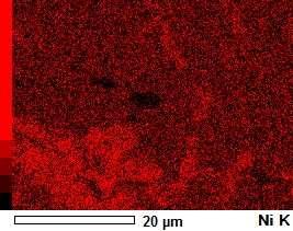
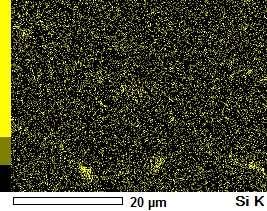

6 SEM/EDS NbC Fe and Cr depletion Ni and Si enrichment 6


7 Niobium Carbide Post corrosion (polarised) SEM analysis of sensitised 800⁰C, 192 Hr Nb tube where pits initiate at NbC inclusions. C. H. Phuah, Corrosion of Thermally-Aged Advanced Gas Reactor Fuel Cladding, Imperial College London, Localised corrosion seems to nucleate on NbC interfaces C. M. Chan, Localised Corrosion of AGR Fuel Cladding, 2nd NDA seminar, Manchester,
 to conduct Scanning Kelvin Probe-Force Microscopy (SKP-FM) mapping Analysis of Volta potential differences on the")
8 AFM / SKPFM Atomic Force Microscopy (AFM) is a type of scanning probe microscopy Probe is in the form of a small cantilever which rasters across the surface under interaction of localised forces Using feedback from the topography, the probe hovers at a user defined height (50 nm) to conduct Scanning Kelvin Probe-Force Microscopy (SKP-FM) mapping Analysis of Volta potential differences on the microscale allows for evaluation on the relative nobility of phases within the SS 8


9 AFM - Carbide Site AFM Cr-carbides KPM AFM: Lighter areas proud of matrix KPM: Darker areas represent nobility Not all GBs show high Volta potentials


10 AFM - Carbide Site AFM KPM Cr carbide appears to show a higher potential wrt matrix


11 AFM - Carbide Site AFM KPM Heavily Cr-depleted area, discrete areas sensitive to IGC


12 AFM - NbC Site AFM KPM NbC acts cathodic with respect to the matrix
 Both current and charge decrease with polish depth Scale 179.2 66.3 117 56 0.37 0.")
13 Anodic charge, C Repassivation charge, C Anodic max current, ma Repassivation max current, ma Ratio (Charge) Ratio (Current) DL-EPR Test Test for sensitisation 0.5 Mol dm -3 sulphuric acid Mol dm -3 potassium thiocyanate Ratio of charge and current are a function of the degree of sensitisation (DOS) Both current and charge decrease with polish depth Scale µm Polish Less sensitised away from surface 70 µm Polish

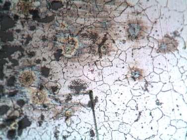
14 Specimen Preparation Technique Mount specimen in resin at an oblique angle Grind hematite scale away This leaves highly sensitised areas to be investigated Green area represents area to be imaged The dark outer box represents the Hematite oxide which forms after conducting the heat treatment Orange sections represent areas in which there is a greater degree of sensitisation, compared to the grey area in the centre 14
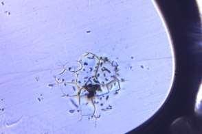
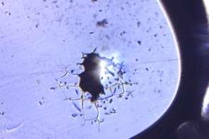
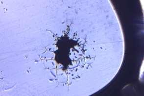
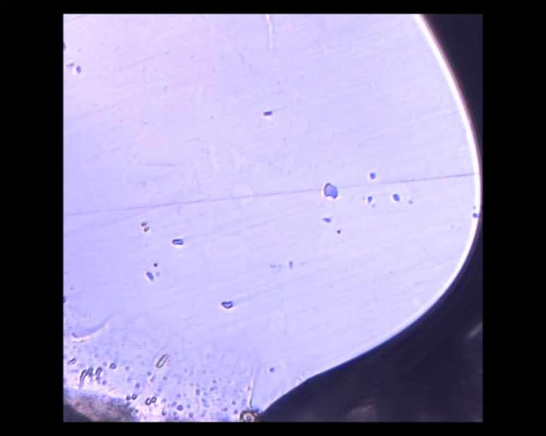
15 Time Lapse Microscopy 15
16 c. 175um

17 3 Mol dm -3 NaCl, OCP, 48hr c. 400um

18 Pre/Post Experiment c. 400um


19 Corrosion under scale c. 100um
20 TL-AFM Electrochemical cell glass block used with o-ring Contact mode imaging used with low (relative) setpoint; 0.36 V V Tip velocity 30 μs -1 (0.3 Hz line rate) 50 μm 2 scans = ~30 mins 1 Mol dm -3 NaCl
21 TL-AFM Optical a b Manifestation of IGC c Development of corrosion product ring d Corrosion product continues to increase despite AFMs showing little increase in IGC TL-AFMs at (a) 30, (b) 60, (c) 120, (d) 240 minutes Immersion at open circuit potential in 1 Mol dm-3
22 Corrosion Product d FeO(OH) OHproduced at cathode Fe2+ produced at anode S. B. Lyon, Corrosion of Carbon and Low Alloy Steels, Shreir s Corros.,

23 TL-AFM NbC? Anodes appear as intergranular pits Pit covers evident Grain boundary swelling Corrosion around what appears to be NbC inclusion TL-AFMs at (a) 30, (b) 60, (c) 120, (d) 240 minutes Immersion at open circuit potential in 1 Mol dm-3

24 TL-AFM 3D Each frame = 30 mins Corrosion pits but passivate rapidly as pit covers disturbed Large amount of corrosion product visible
25 Conclusions RIS simulated by a heat treatment NbC still present after solution anneal (SEM/EDS) NbC appear noble wrt matrix (SKPFM) In-situ IGC successfully imaged (Optical, AFM) IGC does not appear to affect NbC (TL-AFM) NbC appears to be acting as a cathodic activator (TL-AFM) Corrosion initiates at inclusion, and highly sensitised grain boundaries through an intergranular pitting mechanism 25

26 Acknowledgements Geraint Williams Steve Walters Justin Searle Simon Dumbill May Chan MACH1, Swansea University Nuclear Decommissioning Authority National Nuclear Laboratory Westinghouse fuels Ltd. Thank you!!
27 EXTRA SLIDES 27
28 Polarised Time-lapse Microscopy 0.01 Mol dm -3 NaCl SCE reference, Pt gauze counter electrode Corrosion follows grain boundaries Intergranular-pitting mechanism present IGC initiates at surface scratch which is also the location of triple point grain boundary NbC inclusions appear to be unaffected (perturbed system) 28
29 Potentiodynamic Trace 29

30 TLM 250µm 30
31 200µm 31


32 Post TLM - Optical IG Pitting 32