MULTI-SCALE APPROACH TO INVESTIGATE THE TENSILE AND FRACTURE BEHAVIOR OF NANO COMPOSITE MATERIALS
|
|
|
- Arron Todd
- 5 years ago
- Views:
Transcription
1 MULTI-SCALE APPROACH TO INVESTIGATE THE TENSILE AND FRACTURE BEHAVIOR OF NANO COMPOSITE MATERIALS Dr. C. T. Liu AFRL/PRSM, 10 E. Saturn Blvd. Edwards AFB CA Tel. No ; Fax No Address: Narrative Description of the Program: This program is concerned with the effects of nano size particles on the tensile and fracture behavior of particulate composite materials. The program s basic approach involves a blend of experimental and analytical studies. In general, mechanisms and mechanics involved in the damage process and cohesive fracture are emphasized. Special issues that will be addressed are: (1) To what extent and by what mechanism do the nano size particles affect damage initiation and evolution processes, deformation process, and crack growth behavior? (2) What are the deformation and failure mechanisms on the meso and the macro levels? (3) How do the nano size particles affect the characteristics of the interphase between the particle and binder? And (4) what is role of the interphase properties in damage initiation and evolution processes? The objectives of the proposed research are to (1) obtain a fundamental understanding of the effects of nano size aluminum particles on the constitutive and crack growth behavior of particulate composite materials, (2) investigate the effects of aluminum particle size on deformation mechanism, damage process, hysteresis, and fracture strength under a constant strain rate condition, (3) determine the role of the interphase in damage initiation and evolution processes, (4) determine the deformation and failure mechanisms on meso and macro scales, (5) develop a statistical based technology to evaluate the inherent material quality,and (6) provide guidance for developing high strength solid propellants containing nano size particles. Detailed Technical Approach for FY05: In FY 05, there are two major tasks: Task 1 Meso and Macro Scale Strain Measurements and Damage Analysis Task 2 Multi-Scale Modeling on Particles Interaction. Task 1 Meso and Macro Scale Strain Measurements and Damage Analysis In FY 05, the deformation and failure mechanisms in two composite materials [Tetrahydrofuran- Polyethylene Glycol (TPEG)) with 20%by weight of 6 micron aluminum particles and 10% by weight of 40 micron AN particles and TPEG with 20% by weight of 0.2 micron aluminum particles and 10% by weight of 40 micron AN particles ] were investigated. The specimens were tested under a constant strain rate condition in a Hitachi scanning electron microscope (model S- 2460N), which was equipped with a displacement controlled loading device. The crosshead of the loading device can travel continuously. Approved for public release; distribution unlimited
2 Report Documentation Page Form Approved OMB No Public reporting burden for the collection of information is estimated to average 1 hour per response, including the time for reviewing instructions, searching existing data sources, gathering and maintaining the data needed, and completing and reviewing the collection of information. Send comments regarding this burden estimate or any other aspect of this collection of information, including suggestions for reducing this burden, to Washington Headquarters Services, Directorate for Information Operations and Reports, 1215 Jefferson Davis Highway, Suite 1204, Arlington VA Respondents should be aware that notwithstanding any other provision of law, no person shall be subject to a penalty for failing to comply with a collection of information if it does not display a currently valid OMB control number. 1. REPORT DATE 26 JUL REPORT TYPE 3. DATES COVERED - 4. TITLE AND SUBTITLE Multi-Scale Approach to Investigate the Tensile and Fracture Behavior of Nano Composite Materials 6. AUTHOR(S) C Liu 5a. CONTRACT NUMBER 5b. GRANT NUMBER 5c. PROGRAM ELEMENT NUMBER 5d. PROJECT NUMBER e. TASK NUMBER f. WORK UNIT NUMBER 7. PERFORMING ORGANIZATION NAME(S) AND ADDRESS(ES) Air Force Research Laboratory (AFMC),AFRL/PRSM,10 E. Saturn Blvd.,Edwards AFB,CA, PERFORMING ORGANIZATION REPORT NUMBER 9. SPONSORING/MONITORING AGENCY NAME(S) AND ADDRESS(ES) 10. SPONSOR/MONITOR S ACRONYM(S) 12. DISTRIBUTION/AVAILABILITY STATEMENT Approved for public release; distribution unlimited 13. SUPPLEMENTARY NOTES 11. SPONSOR/MONITOR S REPORT NUMBER(S) 14. ABSTRACT This program is concerned with the effects of nano size particles on the tensile and fracture behavior of particulate composite materials. The program s basic approach involves a blend of experimental and analytical studies. In general, mechanisms and mechanics involved in the damage process and cohesive fracture are emphasized. Special issues that will be addressed are: (1) To what extent and by what mechanism do the nano size particles affect damage initiation and evolution processes, deformation process, and crack growth behavior? (2) What are the deformation and failure mechanisms on the meso and the macro levels? (3) How do the nano size particles affect the characteristics of the interphase between the particle and binder? And (4) what is role of the interphase properties in damage initiation and evolution processes? The objectives of the proposed research are to (1) obtain a fundamental understanding of the effects of nano size aluminum particles on the constitutive and crack growth behavior of particulate composite materials, (2) investigate the effects of aluminum particle size on deformation mechanism, damage process, hysteresis, and fracture strength under a constant strain rate condition, (3) determine the role of the interphase in damage initiation and evolution processes, (4) determine the deformation and failure mechanisms on meso and macro scales, (5) develop a statistical based technology to evaluate the inherent material quality,and (6) provide guidance for developing high strength solid propellants containing nano size particles. 15. SUBJECT TERMS
3 16. SECURITY CLASSIFICATION OF: 17. LIMITATION OF ABSTRACT a. REPORT unclassified b. ABSTRACT unclassified c. THIS PAGE unclassified 18. NUMBER OF PAGES 38 19a. NAME OF RESPONSIBLE PERSON Standard Form 298 (Rev. 8-98) Prescribed by ANSI Std Z39-18
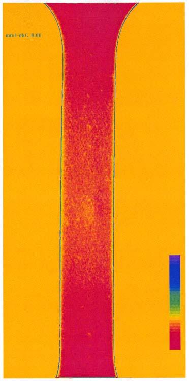
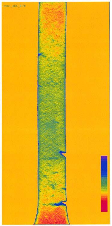
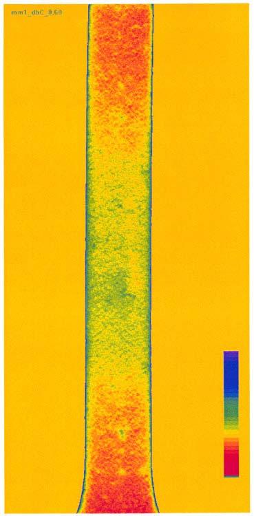
4 Experimental findings reveal that the deformation mechanisms, large displacement and ligament formation, and the failure mechanisms, voids formation and elongation around the particles, of the two materials are similar (Fig.1). In addition, the effects of microstructure on the strain fields in specimens made of solid propellant and in specimens made of pure matrix material are similar. In FY04, we analyzed the X-ray data in a 2mm x 2mm area where a crack was formed. In FY 05, we conducted similar analysis at different locations where cracks were formed in different specimens. The results of the analyses reveal that the statistical density function is a function of the applied strain. On the first approximation, when the applied strain level is below a critical applied strain level, the statistical density function can be assumed to be a normal statistical density function. When the applied strain level is above the critical applied strain level, the statistical density function starts skewing to the right. Currently, we are continuing to analyze the x-ray data to develop a technique to determine the critical x-ray intensity, or critical damage intensity, for crack formation. The developed technique can be used to evaluate the quality of a solid propellant. In FY04, we used Lockheed Research Lab s High Energy X-Ray Systems to investigate microstructural evolution in a solid propellant specimen under a constant strain rate condition. Experimental findings reveal that, at a critical applied strain level, a crack is formed in the weak region in the specimen, and it doesn t propagate. As the applied strain level is increased, the number of the non-propagating cracks increases. Finally, two non-propagating cracks coalesce, resulting in a long crack which propagates and leads to the fracture of the specimen. In FY 05, in order to obtain a fundamental understanding of the mechanism associated with the nonpropagating crack, we conducted numerical modeling analyses to determine the effect of inhomogeneity of microstructure on the stress field at the crack tip. Figure 2 shows the geometry of the nonhomogeneous specimen with an edge crack in a soft region in the specimen. The soft region is modeled by reducing the volume fraction of particle, and the corresponding Young s modulus is calculated by the use of Mari-Tanaka method. The results of modeling analyses show that the normal stress at the crack tip decreases as the volume fraction of particle is reduced (Table 1). If the stress is below a critical stress for crack growth, the crack will not propagate. The damage field near the crack tip in edge-cracked sheet specimens, made of a solid propellant, subjected to cyclic loads was investigated using Lockheed Martin Advanced Technology Center s High-Energy X-Ray Systems. The specimen was subjected to an incremental cyclicstrain loading condition, which had a triangular shape and seven strain cycles. The minimum strain level for each cycle is 0% and the maximum strain level for each cycle were 1.75%, 4.55%, 9.5%, 9.5%, 10%, 15%, and 19%. After the last strain cycle, the specimen was pulled to fracture at a constant strain rate of 0.05 cm/cm/min. that was used during the cyclic-strain test. The recorded x-ray data were processed to create a visual indication of the energy absorbed in the material. A region of high absorption (i.e., a low damage area) produced a dark area, whereas a region of low absorption (i.e. a high damage area) produced a light or white area, with 4094 shades of gray in between. Experimental findings reveal that, when the specimen is strained, the high intensity of stress near the crack tip will damage the material. As the material is damaged, the x-ray image shows a light Approved for public release; distribution unlimited
5 area near the crack tip. Initially, the size of the light area or the size of the damage zone increases with increasing applied strain level. This phenomenon is expected because the local stresses near the crack tip increase with increasing applied strain level. However, the damage zone size will not continuously increase with increasing applied strain level. Real-time x-ray data reveal that the damage zone size starts decreasing when a certain applied strain level is reached. This applied strain level is close to the strain level corresponding to the maximum applied stress. Since the applied stress will continuously decrease beyond the maximum applied stress, the local stress near the crack tip will also decrease. Since damage zone size is directly proportional to the local stress near the crack tip, the decrease in applied stress results in a reduction in local stress near the crack tip, which, in turn, results in a reduction in damage zone size. Figure 3 shows the contours of transmitted x-ray energy near the crack tip when the specimen is strained at 9.5% applied strain for 2 min and 44 sec. In this figure, the number between two contour lines is the minimum intensity level of a range of I t between the minimum intensity level and the next intensity level. A small number indicates that the intensity of the transmitted x-ray energy is high or the damage is high. These contour plots show the details of the size and shape of the damage zone as well as the damage intensity inside the damage zone. According to Fig. 3, it is seen that under the constant strain condition, the crack propagates and the damage zone size and the intensity of damage increase. It is known that for a viscoelastic material the stress in the material will relax under the constant strain condition. The growth of the crack and the increase in the damage zone size near the crack tip is probably due to the material s viscoelastic nature. In other words, a time scale or phase shift exists between the applied stress and the local stress in the material, especially near the crack tip. Under this condition, even the global stress starts relaxing but the local stress near the crack tip is still high enough to propagate the crack. It is interesting to point out that, after the specimen is unloaded to 0% strain from a higher applied strain during the cyclic loading test, the damage zones still exist. Due to viscoelastic nature of the material, the microvoid size will decrease with increasing time. Consequently, the damage zone size and the damage intensity will decrease as the length of time is increased. Task 2 Multi-Scale Modeling on Particles Interaction In this task, two methods, boundary element method and element overly method, were used to investigate the stress distribution in a unit cell with different number of particles. In the first study, linear elastic analysis, based on the boundary element method, was used to determine (1) the stress distribution among the randomly distributed particles with different size distributions and (2) the effective material properties of the material. The results of modeling analysis reveal that as long as the particle volume fraction is the same and there is no debonding at the particle-matrix interface the effective material properties, Young s modulus and Poisson s ratio, are independent of the distribution of the particle size. For example, for a 10% volume fraction of particle, the Young s modulus and the Poisson s ratio are psi and when the particles sizes distributions are 200 and 0.2 microns and 200, 50, 0.2 microns. It is known that the efficiency of the boundary element method diminishes when the material undergoes nonlinear deformation. In order to analyze particulate composites with the matrix material deformed nonlinearly, a method, based on a combination of the element overlay method Approved for public release; distribution unlimited
6 and the homogenization method, is developed, which is suited for the mesoscopic analysis of particulate composites. In the method, each particle and its vicinity is modeled by a finite element mesh, which is called a local model or mesoscopic model. A unit cell or a structure made of the composite is discretized by a coarse finite element mesh, which is called a global model or macroscopic model. In the element overlay method the local models are superposed on the global model and the material properties are specified such that the global model has the material properties of matrix material only and the materials other than matrix material are specified in the local model. By comparing with the ordinary finite element method, the element overlay method is much simpler to build and modify when a numerical model consists of a large number of particles. In order to evaluate the accuracy of the element overlay method, stress distributions in a plate containing one or four circular holes under a uniform tension are determined, based on the element overlay method and the ordinary finite element method, and the results are shown in Fig. 4. According to Fig.4, it is seen that a good correlation exists between the stresses determined by the two methods. The element overlay method was used to determine the two-dimensional stress distribution in a unit cell containing either 250 randomly distributed holes or 250 randomly distributed particles and the three-dimensional stress distribution in a unit cell containing either 35 randomly distributed voids or 35 randomly distributed spherical particles. Plots of the distribution of the normalized stress, which is equal to the calculated stress divided by the applied stress, for the 35 void/particle are shown in Fig.5. The results of the analyses indicate that, for the void model, high stresses are developed on either side of the void whereas, for the particle model, high stresses are developed at the top and the bottom of the particle. In addition, the randomly distributed particles induce randomly distributed high stress locations in the material. Volume Fraction of Particle (VFP) σ yy (KPa) (Region B) σ yy (KPa) (Region C) 50% % % % Table 1. Summary of σ yy at Different Regions for Different Volume Fractions of Particle Approved for public release; distribution unlimited


7 Figure 1. Local Behavior at Crack Tip. Figure 2. Specimen Geometry (a) Time = 11 min. 5 sec. (b) Time = 8 min. 21 sec. Figure 3. Iso-Intensity Contour Plots of X-Ray Images at 9.5% Applied Strain. Approved for public release; distribution unlimited
 Holes (b) Particles Figure 5. Distributions of Normalized Stress in a Section of the Unit Cell.")
8 Element Overlay Method Figure 4. Stress Distributions versus the Distance from the Center of the Model. (a) Holes (b) Particles Figure 5. Distributions of Normalized Stress in a Section of the Unit Cell. Approved for public release; distribution unlimited


9 Multi-Scale Approach to Investigate the Tensile and Fracture Behavior of Nano Composite Materials. AFOSR Program Review 30 August 2005 C. T. Liu AFRL/PRSM Edwards AFB CA. Distribution A: Approved for public release; distribution unlimited
10 Multi-Scale Approach to Investigate the Tensile and Fracture Behavior of Nano Composite Materials. Objectives: Obtain a fundamental understanding of the tensile and fracture behavior of nano composite materials. Develop a microstructure and statistical based technology to evaluate the inherent material quality. State of the Art: Uniaxial tensile and combustion characteristics tests were conducted. Fracture behavior not studied. Approaches: Multi-scale experimental, analytical, and numerical modeling analyses Damage mechanics, experimental mechanics, fracture mechanics, and statistical mechanics Applications: Strategic and tactical missile systems. 2
11 Multi-Scale Approach to Investigate the Tensile and Fracture Behavior of Nano Composite Materials. Past Year Accomplishments: Conducted constant strain rate tests on composite material (TPEG and 20% by weight of 0.2 micron AL particles + 10% by weight of 40 micron AN and TPEG+20% by weight of 6 micron AL + 10% by weight of 40 micron AN). Investigated the deformation and failure mechanisms. Conducted X-ray tests to determine damage characterization near crack tip in a solid propellant under a cyclic loading condition. Conducted 2D and 3D multi-scale modeling analysis to determine stress fields in randomly distributed particles system. Research Payoff: Provide a fundamental understanding of the role of nano size particles on the deformation and damage processes as well as crack growth behavior. Provide guidance for developing high strength nano composite materials. Related Research Program: EPFC Program (AFRL/PRSP) 3
12 Multi-Scale Approach to Investigate the Tensile and Fracture Behavior of Nano Composite Materials. Uniqueness of Research: Unique Material (dual function and highly filled multisize particles material). Account for microstructurral effect on tensile and crack growth behavior. Multi-scale microstructure controlling factors for damage and crack growth. Bridge the gap between meso and macro analyses. 4
13 Multi-Scale Approach to Investigate the Tensile and Fracture Behavior of Nano Composite Materials. Success Story: Based on multi-scale strain measurements and multi-scale analyses of x-ray data, techniques are developed which can be used to predict the representative area or the representative volume of particulate composites with good accuracy. Based on a combination of representative volume and multi-scale analysis approach, microstructure and damage evolution processes can be simulated with good accuracy. Based on an element overlay approach, an efficient and accurate numerical modeling is developed which can be used to predict elastic and elastic-plastic stress fields in particulate composites. 5
14 Multi-Scale Approach to Investigate the Tensile and Fracture Behavior of Nano Composite Materials. Applications: The developed techniques can be used to formulate high performance solid propellants for future strategic and tactical missile systems. 6

 embedded in polymer matrix Approach: Experimental Mechanics Damage Mechanics Fracture Mechanics Statistical Mechanics")
15 Multi-Scale Approach to Investigate the Tensile and Fracture Behavior of a Nano Composite Materials Technical Challenge: Multi-Scale Failure Mechanisms Microstructure Controlling Factors for Failure are Different for Different Length Scales Meso-Scale Macro-Scale Interphase region AN particle (200 μm) Aluminum Nanoparticles (~0.18 μm) embedded in polymer matrix Approach: Experimental Mechanics Damage Mechanics Fracture Mechanics Statistical Mechanics Numerical Modeling Nondestructive Testing and Evaluation 7

16 Testing Set-Up 8


17 Top View of TPEG + 10% by Weight of 40 Micron AN + 20% by Weight of 0.2 Micron AL 9

18 Top View of TPEG + 10% by Weight of 40 Micron AN + 20% by Weight of 6 Micron AL 10

19 X-Ray Testing Set-up Distribution Approved A: for Approved public release; for public distribution release; distribution unlimited. unlimited 11


20 X-Ray Images and Iso-intensity Contour Plots of X-Ray Images 0% / applied strain 9.5% / applied strain 0% / applied strain 9.5% / applied strain 12
21 X-Ray Images and Iso-intensity Contour Plots of X-Ray Images(9.5% Applied Strain) 0% applied strain when t > 2 min. 32 sec. Time = 2 min. 32 sec. Time = 8 min. 21 sec. 0% applied strain when t < 8 min. 21 sec. Time = 2 min. 32 sec. Time = 8 min. 21 sec. 13
22 X-Ray Images and Iso-intensity Contour Plots of X-Ray Images(9.5% Applied Strain) 9.5% applied strain when t < 8 min. 21 sec. Time = 8 min. 21 sec. Time = 11 min. 5 sec. 9.5% applied strain when t < 11 min. 5 sec. Time = 8 min. 21 sec. Time = 11 min. 5 sec. 14

23 X-Ray Images 15

24 Histogram of Ix as a Function of Stretch 16

25 Histogram of Ix as a Function of Stretch 17
26 Percentage of I x Exceeds I xc Versus Stretch Percentage of I x Exceeds a critical I x 18

27 Determination of Effective Material Properties Using Numerical Modeling Techniques Particle size Volume fraction(%) Number of particle Effective elastic modulus(mpa) Effective Poisson's ratio Particle size Volume fraction(%) Number of particle Effective elastic modulus(mpa) Effective Poisson's ratio Particle Size Young s Modulus (Test) 6 micron 0.53 MPa 0.2 micron 0.66 MPa 19


28 Comparison of Finite Element and Element Overlay Methods Both solutions agree very well Element Overlay Method Normalized stress distribution along X1-X1 FEM Analysis Element Overlay Method AVE Distribution of normalized stress σ /σ

29 Two-Dimensional Linear Elastic Multi-Scale Stress Analysis 250 holes are randomly distributed Hole: E* / E = 1 / 100 Distribution of normalized stress σ /σ AVE 21

30 Two-Dimensional LinearElastic Multi-Scale Stress Analysis 250 particles are randomly distributed Hole: E* / E = 10 Distribution of normalized stress σ /σ AVE 22


31 Three-Dimensional Linear Elastic Multi-Scale Stress Analysis Voids: E* / E = 1 / 100 Particle: E* / E = 10 overview Local model section 23


32 Three-Dimensional Linear Elastic Multi-Scale Stress Analysis 35 Voids are randomly distributed 35 Particles are randomly distributed Voids: E* / E = 1 / 100 Particle: E* / E = 10 Distribution of 22 AVE normalized stress σ /σ 22 (in a section) 24

 Global mesh is")
33 Three-Dimensional Elastic-Plastic Multi- Scale Stress Analysis (9 Particle) Global mesh is 10x10x10 25
")

 Section through the center")
34 Three-Dimensional Elastic-Plastic Multi- Scale Stress Analysis (9 Particle) Equivalent stress (elastic) 3 Overall Strain ε = 6 10 ε = 0.03 Overall Strain Equivalent stress (elastic-plastic) Section through the center of the cube Equivalent strain (elastic-plastic) 26


 Equivalent strain")
35 Equivalent stress (elastic) 3 Overall Strain ε = 6 10 Three-Dimensional Elastic-Plastic Multi-Scale Stress Analysis ε = 0.03 Overall Strain Equivalent stress (elastic-plastic) Equivalent strain (elastic-plastic) Offset section through 4 particles 27
36 Numerical Modeling on Inhomogeneity of Microstructure with Crack 28
37 yy Numerical Modeling on Inhomogeneity of Microstructure with Crack Volume Fraction of Particle (VFP) Young s Modulus E (KPa) Poisson s Ratio 70% % % % % % Young s Modulus and Poisson s Ratio Computed by Mori-Tanaka Method Volume Fraction of Particle (VFP) (KPa) (region B) (KPa) (region C) 50% % % % Maximum Value of Sigma yy vs. Volume Fraction of Particles in the Soft Region for Region B and C 29


38 Numerical Modeling on Inhomogeneity of Microstructure with Crack S, S22 (Ave. Crit.: 75%) e e e e e e e e e e e e e e e e e e e+02 S, S22 (Ave. Crit.: 75%) e e e e e e e e e e e e e e e e e e e+02 yy Distributions of sigma YY near the crack tip with VFP = 50% in the soft region computed for (a) region B (b) region C 30


39 Determination of Effective Material Properties for Different Percentages of Dewetted 6 Micron Particles using Numerical Technique Dewetted particles are in red 31
40 Conclusions 1. The damage zone size and the damage intensity in the damage zone are highly dependent on the loading history. 2. Under constant strain condition, Crack propagates 3. The x-ray technique is a promising technique to monitor damage evolution during crack propagation. 4. The reduction of the crack tip stress in the soft region is a contributing factor to the existence of the non-propagating crack. 5. The multi-scale modeling technique, based on the element overlay method, is an accurate and efficiency technique to determine the effect of particle interaction on the stress field in particulate composites. 32