Arch. Metall. Mater., Vol. 61 (2016), No 2B, p
|
|
|
- Camilla Logan
- 5 years ago
- Views:
Transcription
1 Arch. Metall. Mater., Vol. 6 (206), No 2B, p DOI: 0.55/amm A. POSMYK* #, J. MYALSKI**, B. HEKNER** GLASSY CARBON COATING DEPOSITED ON HYBRID STRUCTURE OF COMPOSITE MATERIALS This paper presents a method of production metal matrix composites with aluminum oxide foam covered by glassy carbon layer used as reinforcement. The glassy carbon coating was formed for decreasing of friction coefficient and reducing the wear. In first step of technology liquid glassy carbon precursor is on ceramic foam deposited, subsequently cured and carbonated at elevated temperature. In this way ceramic foam is covered with glassy carbon coating with thickness of 2-8 μm. It provides desirable amount of glassy carbon in the structure of the material. In the next step, porous spheres with carbon coating are infiltrated by liquid matrix of Al-Cu-Mg alloy. Thereby, equable distribution of glassy carbon in composite volume is achieved. Moreover, typical problems for composites reinforced by particles like sedimentation, agglomeration and clustering of particles are avoided. Tribological characteristics during friction in air versus cast iron as a counterpart were made. Produced composites with glassy carbon layer are characterised by friction coefficient between , thus meeting the typical conditions for solid lubricants. Keywords: hybrid composite, glassy carbon, ceramic foam, solid lubricant, wear. Introduction Nowadays the construction of vehicles aims at reducing the weight of vehicles for fuel saving and the amount of harmful wastes emitted into environment. Lower vehicle mass improves vehicle dynamics due to lower inertia of the moving parts. Mass reduction can be achieved through structural designing and the use of engineering materials with lower density and higher strength. Thus, the composites which feature higher specific strength defined as the relation of strength and density are classified as engineering materials [,2]. New trend in designing and manufacturing vehicle parts is based on replacing lubricating oils with solid lubricants embedded into the surface layers of engineering materials [3,4]. This enables to reduce friction resistance and the wear of sliding parts as well as to decrease the amount of lubricating oils used to ensure faultless sliding. At the Silesian University of Technology the method of obtaining a new generation composite containing embedded glassy carbon which functions as a solid lubricant has been developed [5-7]. The uniqueness of the elaborated technology is the fact that glassy carbon is generated directly in a ceramics from previously introduced precursor. Such solution, compared with the so far applied methods, where the prepared carbon particles are mixed with matrix alloy [8], appear to offer some advantages. Firstly, the manufacturing costs are lower because there is no need for expensive procedure of mixing the reinforcing phase with melted matrix. Secondly, glassy carbon distribution within the entire volume of the composite is uniform, with sedimentation or agglomeration and particles clustering being no matter of concern. Similar effect might be achieved in composites with porous ceramic matrix saturated with glassy carbon precursor subjected to pyrolysis in the presence of argon [9]. The presence of uniformly distributed glassy carbon greatly affects tribological properties of the composite. This is possible due to low shear resistance and high hardness as well as excessive resistance of glassy carbon to high temperatures. An additional advantage seems to be low thermal expansion (.2 to K ). Friction coefficient determined during rubbing against cast iron GJL-350 in the conditions of friction in air ranges between 0.08 to The presented article describes the method of manufacturing new generation composite and its selected properties. The composite is characterized by the matrix of light metals casting alloys (Mg, Al), and hybrid reinforcing phase of ceramic foam modified with glassy carbon which acts as solid lubricant. 2. Production of composites Porous preforms made of aluminum oxide or silicon carbide with high open porosity into which liquid carbon precursor is introduced e.g. furfuryl polyalcohol constitute the basis for a composite. Soaked porous ceramic sample is subjected to catalytic acting (e.g. hydrochloric acid) in temperature ranging from * SILESIAN UNIVERSITY OF TECHNOLOGY, FACULTY OF TRANSPORT, KATOWICE, POLAND ** SILESIAN UNIVERSITY OF TECHNOLOGY, FACULTY OF MATERIALS ENGINEERING AND METALLURGY, KATOWICE, POLAND # Corresponding author: andrzej.posmyk@polsl.pl

2 to 90 C for monomer polymerization from furfuryl alcohol. This is then followed by precursor pyrolysis in argon atmosphere in the temperature of about 000 C. The result is a thin film of glassy carbon covering the walls of ceramic spheres and filling the places of joint. The last stage consists in pressure infiltration of pre-forms with liquid matrix alloy. The cast aluminum alloy AC-AlCu3Mg used for manufacturing machine parts has been used. Magnesium, copper and silver alloys can be used as matrix material. Composites with silver alloy matrix can be employed as the material for contacts of current switches working at strong pressure since ceramic foam considerably boosts compressive strength of a composite, whereas glassy carbon reduces friction forces and increases the resistance to high temperatures caused by electric arc during contacts opening. Porosity of ceramics can range from 85 to 95%, which means that the composite would contain 5 to 5% of ceramic reinforcing phase [0,]. Much more extensive porosity decreases compressive strength of a composite as well as its wear resistance. Stereological parameters of ceramic spheres determine both resistance and tribological properties of a composite. The shape and size as well as the presence of open pores in the walls of spheres condition their chance to be saturated with carbon precursor and to be infiltrated with a liquid matrix metal. Larger pores make it easier for the precursor and matrix metal to penetrate. They also shorten the time which the precursor needs to fill the spheres. The impact of stereological features of porous foam upon the properties of a composite requires some additional studies. Viscosity of carbon precursor should be adjusted to the size of pores in ceramic spheres and to the required thickness of a glassy carbon film covering their walls. Lower viscosity facilitates the penetration of the precursor. However, when too low it might lead to the situation where the precursor not only covers the walls, but fills them blocking the introduction of matrix metal. Figure shows the diagram of ceramic, porous spheres immersed in liquid precursor. It also presents the places (4) impossible for the precursor to reach if introduced under atmospheric pressure. For better filling the spaces (4) between the joined spheres, pressure infiltration is required, though hydrostatic pressure should not be so high as to cause damage of the porous structure. Fig.. The model of filling ceramic structure with liquid carbon precursor ( and macrographs of ceramic structure (b) ( 70), sphere wall, 2 a pore in cross section, 3 view of a pore, 4 closed spaces between spheres which might not be introduced by a precursor, 5 glassy carbon layer on ceramic sphere, 6 joined sphere walls, p h hydrostatic pressure of liquid precursor facilitating its penetration into porous spheres 3. Structure and properties of the composite Scanning Microscopic investigations of the structure of composites in individual stages of their production have been performed. Figure 2a presents the structure of ceramic foam before saturation with carbon precursor. Figure 2b presents the structure of foam after saturation with carbon precursor and their pyrolysis. Figure 2b shows joints of the spheres filled with glassy carbon as well as the pores in the walls of the spheres covered with glassy carbon film. In the spheres are pieces of glassy carbon film placed. Microstructure of the composite presented in Figures 3 and 4 confirms that the porous foam has been filled with the glassy carbon and metal matrix. Pores in the oxide spheres make possible to infiltrate the ceramic preform with liquid matrix metal (Fig. 4). When the diameter of the pores is too small, the sphere could be closed with glassy carbon layer. It could leads to none completely filling of the sphere with the liquid metal, what causes inhomogeneous structure of the composite. In Figure 5 could be the lamellar deposits of the glassy carbon in the ceramic sphere observed. The glassy carbon coating is not homogenous (Fig. 4), what mitigate hers removing due to delaminating of single carbon layers. Those thin carbon layers influent the friction processes. Hybrid composite has been elaborated to be used for cylinder liners of piston machines e.g. air compressors working in the conditions of friction in air or combustion engines operating in the conditions of limited lubrication. Preliminary, comparative


 after metal")
")


,")

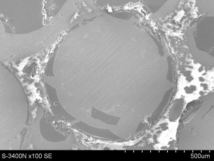
3 047 b) 2 Fig. 2. Ceramic foam before infiltration ( and after saturation with precursor and pyrolysis (b): pore with small diameter, 2 pore with small diameter partially closed with glassy carbon laye FFig. 3. View from the composite reinforced with ceramic foam without carbon ( and with ceramic foam coated with glassy carbon (b) after metal matrix infiltration (b glassy carbon as darker places) b) 3 2 Fig. 4. View from the composite reinforced ceramic foam coated glassy carbon after metal matrix infiltration (, single ceramic sphere coated glassy carbon and filling metal (b), metal matrix, 2 layer of glassy carbon, 3 ceramic foam


 results from the time which a cold machine needs to reach a thermodynamic equilibrium. Fig. 6.")
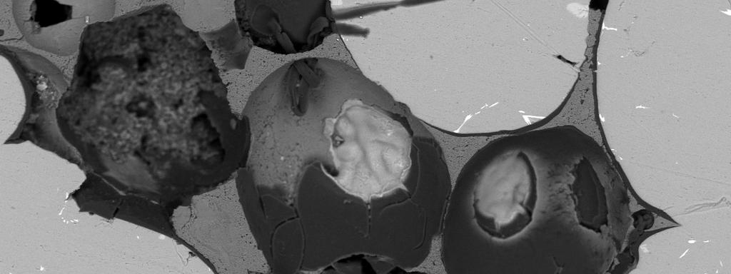
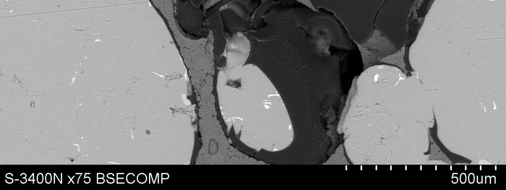
4 048 Fig. 5. The ceramic sphere coated inside with glassy carbon having its characteristic laminar structure tribological research have been carried out on two composite materials, it is: including only aluminum oxide spheres as reinforcement, including aluminium oxide spheres as reinforcement and additionally glassy carbon layer as solid lubricant. The cold start of piston machines perform when cold oil viscosity is too high and splash lubrication is ineffective. Segments cut out of the piston skirt (composite pin of 0 mm diameter, Figure 6) and of the cylinder liner (cast iron GJL-350 disc φ = 45 6 mm) constitute the friction contact at the stand. The short duration of investigation (sliding distance of s = 000 m) results from the time which a cold machine needs to reach a thermodynamic equilibrium. Fig. 6. Composite sample (pin) and countersample (disc) used for tribological investigation Figure 7 shows the average values (trend line) of friction coefficient measured during the sliding of both composites. The mass loss of composite (average from 3 tests) including only aluminia foam was Δmc = 8.7 mg and of composite including aluminia foam coated with glassy carbon Δmcg c = 4 mg. The mass loss of cast iron disc sliding against first composite was Δm = 2,2 mg and against the second was Δm = 2.76 mg. Fig. 7. Friction coefficient in cast iron/composite contact (p = 0,5 MPa, v = 0,55 m/s, friction in air) After tribological investigation the surfaces of samples and countersamples was investigated using scanning electron microscope. The results are presented in Figures 8 and 9. Figure 8 presents the views of the composites surfaces after sliding against cast iron. There are worn and soft cracked oxide spheres (3) filled with matrix alloy () to see (Fig. 8 and surface of one sphere covered with glassy carbon film recovered during friction, 2 in Fig. 8b. On the worn ceramic spheres walls are glassy carbon and graphite wear debris placed. The views of cast iron discs surfaces after sliding against investigated composites have been presented in Figure 9. The SEM micrograph in 9a shows a view of cast iron surface after rubbing against composite including only aluminia foam. The matrix of cast iron is graphite devoid and shows traces of intensive plastic deformation and ploughing. Te micrograph in Fig. 9b shows a view of cast iron surface after rubbing against composite including aluminia foam coated with glassy carbon. There are some graphite lamellas in pearlitic matrix and soft plastic deformation to see.
 with ceramic foam coated with glassy carbon (friction in air, p = 0,5 MPa, v = 0,55 m/s, τ = 30 min),")

.")

5 049 b) Fig. 8. View from the composite surface after sliding against cast iron GJL-350: ( with ceramic foam, (b) with ceramic foam coated with glassy carbon (friction in air, p = 0,5 MPa, v = 0,55 m/s, τ = 30 min), metal matrix, 2 glassy carbon, 3 ceramic foam b) Fig. 9. View from cast iron surface after sliding against composite with alumina foam ( and hybrid composite (b) 4. Discussion of the results The carried out investigations have shown that is possible to introduce the liquid glassy carbon precursor through the pores into the aluminum oxide spheres (Fig. ) used as reinforcing phase. The liquid precursor wets well the surface of aluminum oxide, what causes sedimentation of thin layer of carbon. Pyrolysis of precursor causes blocking of some pores with smaller diameter (Fig. 2b). Figures 3a and 3b show that the liquid carbon precursor introduced into porous spheres and its pyrolysis are effective. Thin film of glassy carbon has been developed upon the walls of Al 2 O 3 spheres and in places of their joints. Some spheres were filled with carbon strips and pores in some spheres were closed with a film of carbon. Their compressive strength is lower than pressure resulting from hydrostatic pressure of the liquid matrix alloy. Therefore after infiltration the spheres which were not filled with the matrix alloy were observed. As the result of infiltration the composite with homogenous structure and with almost uniform distribution of reinforcing material i.e. ceramic spheres and solid lubricant (glassy carbon) has been obtained (Fig. 3). The performed tribological research proves that the introduced glassy carbon improves the tribological properties of the composite. For comparison, tests on a composite which contained only ceramic spheres were done where friction coefficient of about 0.40 was obtained during the final test time. The contact surface was lubricated only with graphite included in cast iron. The GJL- 350 cast iron has a hard pearlitic matrix and soft lamellar graphite precipitates. The precipitate was after a short time removed from cast iron matrix (empty cavities in Fig. 9. During friction of the composite with spheres and glassy carbon the value of friction coefficient was initially 0.06 and 0.2 after 200 m sliding distance. The initial value of friction coefficient was caused by glassy carbon film on the sliding surfaces. After short time some of oxide spheres was broken and their splitters caused increase of friction forces (μ = 0.22). When
6 050 the splitters have been disintegrated, friction coefficient was mitigated and dropped for a shot time on level 0.2 (oscillating friction force have been not showed in the diagram). The view of composite surface (Fig. 8) and cast iron (Fig. 9) after sliding is the evidence of soft friction and dominant abrasive wear which is proved by slight scratches along the direction of friction. Figure 8 shows the revealed carbon film covering the sphere of aluminum oxide with some traces of wear, being the result of friction. Wear products are deposited upon cast iron surface forming discontinuous sliding film. The presence of sliding film from glassy carbon reduces the intensity of wear and friction coefficient in cast iron contact. 5. Summary The carried out investigations have shown that is possible to introduce the liquid glassy carbon precursor through the pores into the aluminum oxide spheres and have confirmed the possibility of production of hybrid composite including ceramic foam. During the process of precursor depositing and its pyrolysis can some pores decrease in diameter, what causes worsening of metal matrix infiltration into the ceramic spheres. Ceramic foam modified with glassy carbon layer (thickness 2-8 μm) as a structural element of hybrid composite can be used as a solid lubricant. The glassy carbon in form of thin coating on the ceramic spheres is regularly distributed in whole composite, which results in better tribological properties (μ = , Δm = 4 mg) compared to composite including only ceramic spheres (μ = , Δm = 8.7 mg). High hardness, low shear strength and laminar structure of glassy carbon cause decreasing of friction forces. Acknowledgements Financial support of Structural Funds in the Operational Programme Innovative Economy (IE OP) financed from the European Regional Development Fund Project No POIG /08 is gratefully acknowledged. REFERENCES [] M. Sanchez, J. Rams, A. Urena, Composites: Part A. 4, (200). [2] K. Shibata, U. Hideaki, Tribology International. 27 (), (994). [3] M. Nakada, Tribology International. 27 (), 3-7 (994). [4] Y. Fukui, Y. Watanabe, Metallurgical and Materials Transactions A: Physical Metallurgy and Materials Science, 27 (2), (996). [5] A. Posmyk, J. Myalski, Solid State Phenomena, 9, (202). [6] A. Posmyk, Composites. 0 (), (200). [7] Method for aluminium-ceramic composite including solid lubricants production, Patent PL, P.3983 [WIPO ST 0/C PL3983] (202). [8] J. Myalski, J. Śleziona, Journal of Materials Processing Technology, 75, (2006). [9] A. Posmyk, H. Wistuba, Archives of Metallurgy and Materials. 56 (4) (20). [0] M. Potoczek, A. Zima, Z. Paszkiewicz, A. Slosarczyk, Ceram. Int. 35, (2009). [] M. Potoczek, Mater. Lett., 62 (), (2008). [2] H. Ernst, An Interpretive Review of 20 th Century Machining and Grinding Research. TechSolve Inc. Cincinati (OH), [3] A. Posmyk, H. Wistuba, P. Falkowski, Composites. (2), 97-0 (20).