Agenda. Hitsaustekniikka Kon Gas Metal Arc Welding Conventional control (solid wire) - Fundaments
|
|
|
- Garey Dorsey
- 5 years ago
- Views:
Transcription
 - Fundaments Materials Joining and Non-Destructive Testing Version 1/2013 Professor Pedro Vilaça (pedro.vilaca@aalto.")
1 Department of Engineering Design and Production Master Degree in Mechanical Engineering Hitsaustekniikka Kon Gas Metal Arc Welding Conventional control (solid wire) - Fundaments Materials Joining and Non-Destructive Testing Version 1/2013 Professor Pedro Vilaça (pedro.vilaca@aalto.fi) Agenda Process fundaments Equipments and accessories Welding parameters Advantages and limitations Transfer modes of filler metal electrode Typical industrial applications Possible imperfections Technological variants Kon : Gas Metal Arc Welding 2 1

 and the workpieces The electrode is stored in a bobbin and is")

2 Fundaments GMAW Process Fusion welding process using the electric arc as heat power source Electric arc is established between a consumable fusible (non thermoionic) electrode (typically of the same physical nature of the workpiece materials) and the workpieces The electrode is stored in a bobbin and is continuously feed into the welding gun by an electrode feed system Kon : Gas Metal Arc Welding 3 Fundaments GMAW Process Apparatus Kon : Gas Metal Arc Welding 4 2

 Arc start is performed with")


3 Fundaments GMAW Process: Apparatus Kon : Gas Metal Arc Welding 5 Fundaments GMAW Process Current: DCEP or AC (still very few applications) Arc start is performed with short-circuit Electrode diameter is typically small (e.g.: 0.8 to 1.2mm) to enable conditions of high current density, which is crucial for the stability of the process (focusing metal transfer) Kon : Gas Metal Arc Welding 6 3


, or mixtures of Argon + CO2 + O2 Kon-67.")
 MAG (promotes reactions of oxidation and reduction) Kon-67.")
4 Shielding gases are used to: Fundaments GMAW Process Promote the protection of weld pool, hot electrode wire and metal transfer Most used shielding gases are: Remove original atmosphere and promote an adequate atmosphere for the plasma formation MIG Argon or Helium or mixtures of both (most used: 50% or 75% de Argon) MAG - CO2 mixtures of Argon + CO2 (5%, 18% or 20%), or mixtures of Argon + O2 (1%, 3%, 5%), or mixtures of Argon + CO2 + O2 Kon : Gas Metal Arc Welding 7 Fundaments GMAW Process MIG (No chemical reactions) MAG (promotes reactions of oxidation and reduction) Kon : Gas Metal Arc Welding 8 4


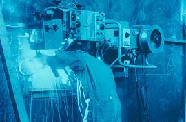
5 Fundaments GMAW: Control Conventional Equipment Kon : Gas Metal Arc Welding 9 Fundaments GMAW: Control Conventional Equipment Kon : Gas Metal Arc Welding 10 5
 1 + 7 5 6 5 Kon-67.")
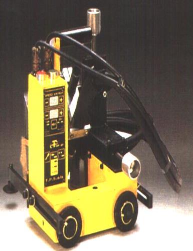
6 1. Power source Equipment Main Components Gas gauges Wire feed system 3. Welding gun (torch) 3 4. Gas cylinder/source 5. Ground and weld cables 6. Ground clamp 7. Chiller (refrigeration system) Kon : Gas Metal Arc Welding 11 Equipment Main Components: General Cautions Ground clamp should be correctly designed/selected for the electrical power involved in weld procedures Clamps and connections should in perfect conditions to avoid hot spots (local sparks) Ensure the electrical insulation of all cable system Electric system should always have ground connection Kon : Gas Metal Arc Welding 12 6


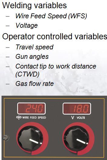
7 Voltage Equipment Power Source: Type Static Conventional Working V-I Typical Ducty-cycle of about 60% Current Constant-Voltage Sources: The Self-Correcting characteristic regulates the electrode burn-off rate Kon : Gas Metal Arc Welding 13 Equipment Power Source: WFS versus Current Wire Feed Speed, WFS: WFS I I 2 where: ; - Constants depending on type and diameter of electrode I Current Stick-out Kon : Gas Metal Arc Welding 14 7


 Kon-67.")

 and threaded metal nut insert (yellow), (3) Shielding")
8 Equipment Power Source: Synergic Control Arc control is based on arc voltage Variable speed in wire feed system Constant-Current Sources Electronic devise continuously assessing arc voltage and comparing it with standard values for the application condition (parameters and characteristics) Kon : Gas Metal Arc Welding 15 Equipment Main Components: Welding Guns GMAW torch nozzle cutaway image. (1) Torch handle, (2) Molded phenolic dielectric (shown in white) and threaded metal nut insert (yellow), (3) Shielding gas diffuser, (4) Contact tip, (5) Nozzle output face Kon : Gas Metal Arc Welding 16 8


9 Equipment Main Components: Feed System Componentes do Sistema: Feeder Rollers Guides Kon : Gas Metal Arc Welding 17 Equipment Feed System: Push/Pull System Sistema de Push/Pull Sistema de Pull Sistema de Push Kon : Gas Metal Arc Welding 18 9


10 Equipment Main Components: Shielding Gas Gauges Kon : Gas Metal Arc Welding 19 Parameters Key Variables Current WFS Voltage Arc length Travel Speed Shielding gas Composition and flow Pre-flow and post-flow time Inductance Electrode Diameter Composition Stick-out extension Kon : Gas Metal Arc Welding 20 10


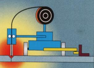
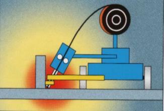
11 Parameters Key Variables: Electrode Stickout Nozzle Contact tip Setback distance Real Stickout Workpieces Working clearance Filler metal electrode Kon : Gas Metal Arc Welding 21 Parameters Influence of Stickout on the Electrode Burn Rate Long Short Kon : Gas Metal Arc Welding 22 11


12 Parameters Key Variables: Inductance Kon : Gas Metal Arc Welding 23 Parameters Key Variables: Inductance Inductance corresponds to the response speed (dynamic) of the power source More relevant for the short-circuit transfer mode Less Inductance Faster response More Inductance Slower response Kon : Gas Metal Arc Welding 24 12
 Particular situations, e.g.: Thin plates: CO 2 +O 2 +Ar or CO 2 +H 2 +Ar Stainless steels : Ar+O 2 or Ar+CO 2 Kon-67.")
13 Parameters Key Variables: Shielding Gases I Inert: All weldable materials but focusing non ferrous metals and stainless steels M1; M2; M3 e C Mixtures of Ar with active gases and active gas only (CO 2 weld of ferrous metals) Particular situations, e.g.: Thin plates: CO 2 +O 2 +Ar or CO 2 +H 2 +Ar Stainless steels : Ar+O 2 or Ar+CO 2 Kon : Gas Metal Arc Welding 25 Parameters Key Variables: Shielding Gases Kon : Gas Metal Arc Welding 26 13


14 Parameters Shielding Gases Influence on Weld Bead Shape Kon : Gas Metal Arc Welding 27 Parameters Shielding Gases Influence on Weld Steels Kon : Gas Metal Arc Welding 28 14


15 Parameters Shielding Gases Influence on Weld Stainless Steels Kon : Gas Metal Arc Welding 29 Parameters Shielding Gases Influence on Spatter Kon : Gas Metal Arc Welding 30 15


16 Parameters Key Variables: Electrode Wire Consumables Kon : Gas Metal Arc Welding 31 Parameters Rules to Select Electrode Wire Electrode should be metallurgically, physically and chemically compatible with base materials Comply with the dilution of the weld bead Comply with the mechanical properties prescribed for the weld joint Comply with weld current/thickness of base material and weld position Kon : Gas Metal Arc Welding 32 16
17 Transfer Modes Most Significant Modes Short-circuit Globular Spray (Axissymmetric and rotational) Drop-spray (axial spray of drop by drop in pulse current) Kon : Gas Metal Arc Welding 33 Transfer Modes Control Factors Shielding gas type (composition) Electrode wire type (composition) Diameter of electrode wire WFS (proportional to current) Static electric characteristic curve (voltage/arc length) Kon : Gas Metal Arc Welding 34 17
18 Transfer Modes Forces Involved in Metal Transfer F g F d Gravity Force Plasma Drag Force F em Electromagnetic Force F F v Surface Tension Force Vaporization Force A drop transfers when: F g + F d + F em > F + F v Kon : Gas Metal Arc Welding 35 Transfer Modes Qualitative Relations for Forces and Weld Parameters Transfer Mode Electric Parameters Main Force in Metal Transfer I [A] V [V] Short-Circuit Low Low Surface Tension Globular Low Medium Gravity Spray High* High Electromagnetic Note: High* - curent above transition current (I>I trans ) The electromagnetic force becomes dominant leading to the immediate deployment of any small drop is formed at the tip of the wire electrode Kon : Gas Metal Arc Welding 36 18
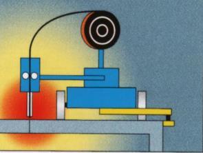
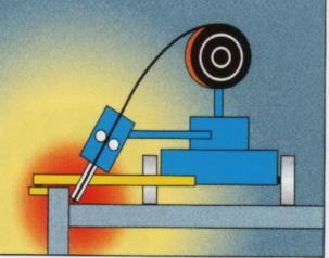
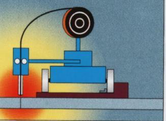
19 Transfer Modes Short Circuit Transfer Mode Kon : Gas Metal Arc Welding 37 Transfer Modes Short Circuit Transfer Mode Kon : Gas Metal Arc Welding 38 19


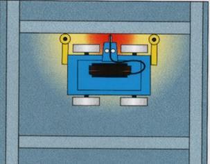
20 Transfer Modes Short Circuit Transfer Mode Kon : Gas Metal Arc Welding 39 Transfer Modes Globular Transfer Mode Characteristics: Drops well above the size of electrode diameter Possible spatter and some short-circuits (affecting arc stability) Kon : Gas Metal Arc Welding 40 20
![Transfer Modes Spray Transfer Mode: Transition Currents Gas Mixtures Transition Current[A] Ar+2%CO 2 226 Ar+8%CO 2](/docs-images/89/97977236/images/21-0.jpg "228 Ar+18%CO 2 257 Ar+5%O 2 196 Ar+8%O 2 215 Ar+3%CO 2 +1%O 2 220 Ar+5%CO 2 +4%O 2 212 Obtaining lower values of")

21 Transfer Modes Spray Transfer Mode: Transition Currents Gas Mixtures Transition Current[A] Ar+2%CO Ar+8%CO Ar+18%CO Ar+5%O Ar+8%O Ar+3%CO 2 +1%O Ar+5%CO 2 +4%O Obtaining lower values of current transition for Spray transfer mode, can became an important factor, especially for carrying out filling passes Kon : Gas Metal Arc Welding 41 Transfer Modes Spray Transfer Mode: Axial Kon : Gas Metal Arc Welding 42 21
 Spray (rotational) Kon-67.")
22 Current (A) Transfer Modes Spray Transfer Mode: Rotational For very high current density conditions in wire electrode it is possible to reach conditions for transferring by Spray with a filament in rotational movement Spray (axial) Spray (rotational) Kon : Gas Metal Arc Welding 43 Transfer Modes Spray Transfer Mode: Drop Spray Transition Current Time (ms) I m I p t t p p I t b b t b V I HI v m Kon : Gas Metal Arc Welding 44 22


23 Transfer Modes Comparison Between Transfer Modes Kon : Gas Metal Arc Welding 45 Transfer Modes Comparison Between Transfer Modes Kon : Gas Metal Arc Welding 46 23


24 Transfer Modes Comparison Between Transfer Modes Drop-Spray Short-Circuit Kon : Gas Metal Arc Welding 47 Transfer Modes Applications Kon : Gas Metal Arc Welding 48 24
25 Advantages (1) The GMAW process enjoys widespread use because of its ability to provide high quality welds, for a wide range of ferrous and non-ferrous alloys, at a low price The ability to join a wide range of material types and thicknesses Simple equipment components are readily available and affordable Higher welder efficiencies and operator factor, when compared to other open arc welding processes GMAW is easily adapted for high-speed robotic, hard automation and semiautomatic welding application Kon : Gas Metal Arc Welding 49 Advantages (2) All-position welding capability Excellent weld bead appearance. Lower hydrogen weld deposit generally less than 5 ml/100 g of weld metal Lower heat input when compared to other welding processes A minimum of weld spatter and slag makes weld clean up fast and easy Less welding fumes when compared to SMAW (Shielded Metal Arc Welding) and FCAW (Flux-Cored Arc Welding) processes Kon : Gas Metal Arc Welding 50 25
26 Limitations The lower heat input characteristic of the short-circuiting mode of metal transfer restricts its use to thin materials The higher heat input axial spray transfer generally restricts its use to thicker base materials The higher heat input mode of axial spray is restricted to flat or horizontal welding positions Very sensitive to air drafts (not allowing out door applications) The use of argon based shielding gas for axial spray and pulsed spray transfer modes is more expensive than 100% CO 2 Kon : Gas Metal Arc Welding 51 Applications The alloy material range for GMAW includes: carbon steel and stainless steel, aluminum, magnesium, copper, nickel, silicon bronze and tubular metal-cored surfacing alloys The GMAW process lends itself to semiautomatic, robotic automation and hard automation welding applications Kon : Gas Metal Arc Welding 52 26
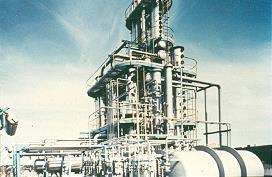
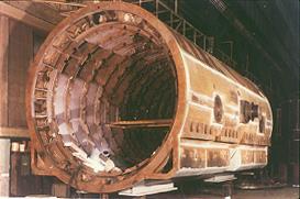
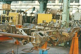

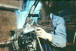
27 Applications Kon : Gas Metal Arc Welding 53 Applications Kon : Gas Metal Arc Welding 54 27
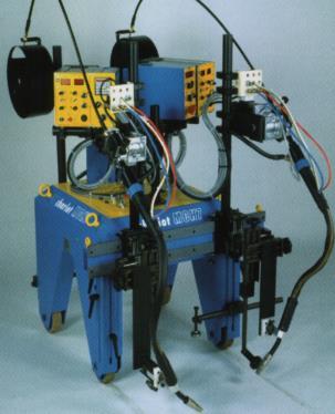
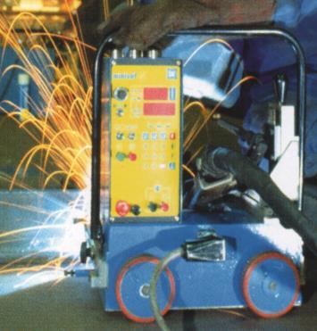
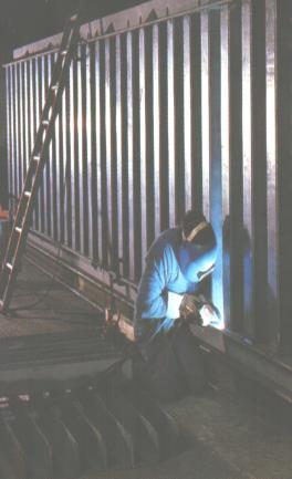
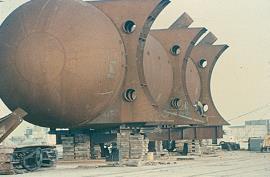
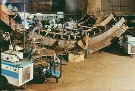
28 Applications Automatization Kon : Gas Metal Arc Welding 55 Applications Automatization Kon : Gas Metal Arc Welding 56 28
29 Applications Automatization Kon : Gas Metal Arc Welding 57 29