Development of innovative hybrid sandwich panel slabs Part I: Experimental results
|
|
|
- Gwendoline Bridges
- 6 years ago
- Views:
Transcription
1 Development of innovative hybrid sandwich panel slabs Part I: Experimental results M. Mastali*, ISISE, Dep. Civil Eng., School Eng., University of Minho Campus de Azurém Guimarães, Portugal. Corresponding author *: Telephone*: I. B. Valente, Assistant Professor, Minho University, Department of Civil Engineering, Campus de Azurém, Guimarães, Portugal. Joaquim A. O. Barros, Full Professor, Minho University, Department of Civil Engineering, Campus de Azurém, Guimarães, Portugal. Delfina M. F. Gonçalves, CIVITEST - Pesquisa de Novos Materiais para a Engenharia Civil, VILA NOVA DE FAMALICÃO, FAMALICÃO, Portugal. ABSTRACT In this paper, a new generation of composite sandwich slab is proposed as a solution for the rehabilitation of slabs in old masonry buildings. An innovative solution was developed during this research formed by four components: a Deflection Hardening Cement Composite (DHCC) layer on the top compression skin, a Glass Fiber Reinforced Polymer (GFRP) skin at the bottom tension surface, GFRP ribs to transfer shear from top to bottom layers, and foam core for thermal-insolation purposes. The DHCC layer contributes significantly for the load carrying and deflection capacity due to its stiffness, compressive strength and toughness, offers resistance to the occurrence of buckling phenomena in the GFRP ribs, improves the performance of this structural concept against impact and fire, and constitutes an excellent medium for the application of finishing materials, like ceramics or timber. Two different hybrid composite slabs were developed and tested, and their behavior was assessed under flexural loading. The results showed that the developed hybrid sandwich slabs accomplish all design requisites for serviceability and ultimate limit states, and assure a stiffness/dead-weight and loadcapacity/dead-weight ratios much higher than conventional structural slab systems. Keywords: Hybrid sandwich panel; Deflection Hardening Cement Composite; GFRP shear connectors; GFRP skin; Polyurethane foam; Flexural loading.
2 1. Introduction Rehabilitation of slabs in old masonry buildings is gaining increasing attention. In fact, rehabilitation of these elements with traditional materials introduces significant dead loads in constructions, increasing their seismic vulnerability, and poses constructive problems associated to transport, elevation and placement operations on narrow accesses. Glass fiber reinforced polymer materials (GFRP) may be successfully used in sandwich panels for the development of new generation of structural elements that present several advantages over traditional ones, namely, higher mechanical performance, cost competitive solutions, better behavior in terms of insulation, lower maintenance and higher durability. Sandwich panel elements formed by composite materials are generally composed of top and bottom FRP skins that assure the flexural capacity and stiffness. A foam core material is used in the middle layer to increase the thermo-insolation and to lighten the construction system, and to contribute for the transference of shear stresses between the FRP skins. Due to their high strength-to-weight and stiffness-to-weight ratios, sandwich panels have been commonly used in aerospace and automotive industries [1]. Civil infrastructures and transportation applications are more recent applications of sandwich structures [1]. The typical sandwich panels used in structural applications consist of two thin and stiff outer skins that have in between them a thick and relatively flexible core, bonded with an adhesive. The skins provide flexural stiffness and strength to the panel, while the core provides shear stiffness, composite action and stress transference between the skins. Typical skin materials include aluminum, FRP systems and, in some structural applications, reinforced or pre-stressed concrete [1]. Core materials typically include polymeric foams, balsa wood or lightweight honeycomb structures. Extensive studies have been done by several researchers on new generation solutions for these structural elements. In 2014, Lu Wang et al. [3] investigated the flexural behavior of an innovative sandwich panel with GFRP face sheets and a foam-web core (GFFW panels). These authors have developed and tested a kind of foam-filled lattice composite sandwich panel (see Fig. 1a). Regarding this, GFRP sheets were used as face skins and GFRP lattice webs were embedded in urethane foams to have innovative foam-filled lattice composite panels. Vacuum
3 assisted resin infusion process was used to manufacture these sandwich panels. An experimental program was carried out to validate the effectiveness of this type of panels in terms of flexural capacity. The experimental results indicate that compared to the traditional sandwich panels, the presence of the webs in the GFFW panels has provided a maximum increase of about 410% in terms of ultimate flexural capacity. Thicker and higher web have significantly increased the ultimate flexural capacity and the initial flexural stiffness of GFFW panels (see Fig. 1a). Delamination between skins and foam core occurs frequently in traditional sandwich panels, which results in a significant decrease of the load carrying capacity and deflection performance of these panels. In 2008 Reis and Rizkalla [4] proposed a new type of sandwich panel consisting of top and bottom skins of GFRP laminates connected together with through thickness unidirectional glass fibers to prevent delamination between skins and foam core (see Fig. 1b). The increase of both the load carrying and deflection capacities was caused by the improved composite action between GFRP laminate skins and foam core through thickness unidirectional glass fibers. In 2010, Fam and Sharaf [5] investigated the flexural performance of sandwich panels comprising polyurethane core, GFRP skins and ribs of various configurations to connect top and bottom GFRP skins and to increase both flexural and shear stiffness of sandwich panel (see Fig. 1c). Their studies showed that by using the ribs, the strength and stiffness of the panels have increased in comparison to sandwich panels without internal ribs. This increase level was dependent of the configuration of the ribs. In the panel without ribs, the shear deformation of the core contributed for the mid-span deflection more than 50%. By using ribs, the shear deformation of the panels was limited to 15-20% of the total deflection. In 2012, Sopal et al. [6] developed GFRP sandwich panels built with GFRP corrugated sheets in addition to the through-thickness fibers to enhance their structural characteristics (see Fig. 1d). Using through-thickness fibers has prevented delamination between skins and foam core, while GFRP corrugated sheets have increased the shear and flexural stiffness for the proposed GFRP sandwich panels. Experimental results showed that adding corrugated GFRP sheet has
4 increased significantly the shear and flexural stiffness, and has delayed the formation of cracks in the foam, resulting an improved resistance to fatigue loading. Norton [7] proposed a deck consisting of two skins of E-glass fabric and truss webs made by GFRP materials to act as flexural members supported by the girders. Each skin was formed by two orthogonal woven fabrics that were stitched together by fibers in the perpendicular direction to form a 3-D GFRP material for the entire cross section [7], Fig. 1e. Balsa cores were inserted between truss GFRP webs to maintain the configuration of the cross section during the vacuum infusion process using epoxy resin. They also used a concrete layer on the top skin to obtain a hybrid sandwich panel. As shown in Fig. 1f, steel and composite connectors were used to connect the top concrete layer to the bottom GFRP skin, as well as to provide a composite action to the GFRP cross section [7]. The tests carried out by these authors showed that the bond between the concrete and GFRP was inadequate (see Fig. 1e). The authors proposed that by roughening the top GFRP skin surface or using a bonding agent, a stronger bond between concrete and top GFRP skin is assured. In 2014, Shams et al. [8] studied the behavior of sandwich panels made by outer layers of Textile Reinforced Concrete (TRC) of 3cm thickness. Alkali-resistant (AR) glass fibers of µm diameter and carbon fibers of 7 µm diameter were used for the reinforcement of these TRC outer layers, Fig. 1g. Additionally, expanded polystyrene, extruded polystyrene, and polyurethane were used as rigid foams in this study. The main purpose of this study was to develop a good connection system between top and bottom concrete skins for the load transference between the two separate concrete layers. For this purpose two types of connectors made of fiber-reinforced polymers (FRP) with low thermal conductivity were employed. The first type of connector consisted of a pin made of glass fiber reinforced polymer, while the second type of connector was a continuous shear grid that was cut as strips at an angle of 45 degree (see Fig. 1g). The obtained results revealed that utilizing continuous shear grids the stiffness and ductility of the sandwich panel is higher than when adopting pin connectors. This fact is maybe derived from the action of the shear grids as ties of a truss system along with the struts formed by the foam core counteracting the shear deformation [8].
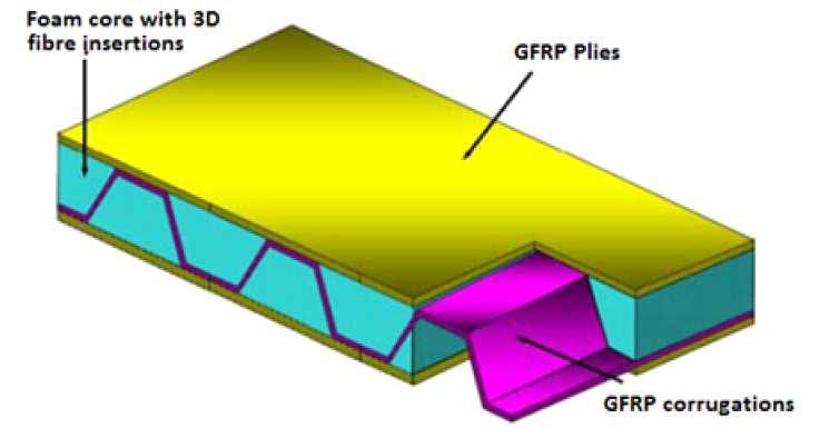
5 Fig Structural concept of the proposed sandwich composite slab The innovative hybrid GFRP-DHCC sandwich slabs proposed in the present paper have a GFRP laminate on the bottom tension skin, and a Deflection Hardening Cement Composites (DHCC) layer on the top compression skin. The DHCC layer has the purpose of increasing the strength and ductility, and allowing easy application of floor cover materials. Utilizing DHCC materials in the compressive layer increases the flexural stiffness of the slab, its acoustic and thermal performance, and resistance against impact. Furthermore, it also provides extra fire protection for the core of the panel. Shear stresses in the proposed new hybrid sandwich panel are transferred by both GFRP ribs and foam core, but it is expected that most part of the stress is carried out by the GFRP ribs. In this case, the shear connection is obtained by executing openings in the upper part of the GFRP ribs (Fig. 1b). These openings are filled with DHCC during casting, forming DHCC dowels that are capable of transferring the mobilized shear forces. Another important aspect related to the sandwich slab is the adhesive bond between the foam and the skin layers. This adhesive bond is introduced for enhancing the transference of shear forces between layers, by contributing in this way for the desired composite action [2]. According to the aforementioned reasons, these structural elements can also be used in other applications like walls or roofs, where a combination of relatively high flexural stiffness and low dead weight justifies the use of constituent materials of higher price than traditional ones. Fig. 2a presents the geometry of the sandwich slab developed in the scope of the present research project. Each component can be considered as relatively weak by itself, but together they provide a strong and lightweight structural system. Fig. 2b presents the holes pattern executed in the GFRP rib to promote an appropriate solution for connecting this rib to the DHCC layer. Furthermore, to ensure proper transfer of stress from the DHCC layer to the GFRP skin through GFRP rib, the connection zone between GFRP skin and rib was further improved with a rounded transition, as shown in Fig. 2c. The main aim of the present study is to assess the performance
6 for serviceability and limit state conditions of the proposed innovative hybrid sandwich panels under flexural loading. Fig 2. Table 1 lists the geometry of the components forming the two types of sandwich panels developed, herein designated by Slab 1 and Slab 2. Each array of the properties corresponds to a column in Table 1, where the meaning of the letters is represented in Fig. 2d. Table Assessment of material properties by experimental tests The developed hybrid sandwich panel is composed of different materials. An extensive experimental program was executed for assessing the properties of GFRP ribs, GFRP skin and Polyurethane foam core. Furthermore, a new fiber reinforced cement mortar for having a deflection hardening behavior (DHCC) and a high ductility was developed within this study Properties of the Deflection Hardening Cement Composites (DHCC) Fiber reinforced cement composites (FRCC) can be classified into two main categories (Naaman and Reinhard, 2005): strain softening cement composites (SSCC); strain hardening cement composites (SHCC) [9]. The strain character of a FRCC is evaluated by executing direct tensile tests with un-notched dog-bone type specimens. If after crack initiation the tensile strength is increased with the tensile strain, the FRCC is assumed pertaining to the SHCC category, otherwise is considered a SSCC. During the strain hardening phase of a SHCC a diffuse crack pattern is formed up to the coalescence of several micro-cracks in the macro-failure crack. The formation of multiple cracks means that fiber bridging action is capable of arresting the further opening of cracks, and as a result, new cracks tend to form in the close vicinity. The macro crack, in general, occurs for a tensile strain higher than 1.5%. In bending (un-notched specimens), SSCC can present a deflection softening (DSCC) or a deflection hardening (DHCC) nature. During the deflection hardening phase of a DHCC several
7 cracks are formed in the tensile face of the specimen, up to the formation of the failure macrocrack. It should be noted that the deflection hardening level is not only influenced by the fiber reinforcement mechanisms and matrix properties, but also by the dimension and cross-section geometry of the sample, since these aspects influence the fiber orientation and distribution [10]. The fiber reinforced mortar developed in the scope of the present research project has a DHCC character. Due to the formation of several cracks, the SHCC and DHCC are also connoted as high to ultra-high ductile materials since during the process of formation of several cracks, high energy is absorbed, and the ultimate tensile strain (in the case of SHCC) and the ultimate deflection (in the case of DHCC) are much higher than the corresponding values at crack initiation. This capability of forming diffuse crack patterns up to relatively high level of deformation has strong benefits in terms of the durability of the materials, since thinner cracks offer more resistance to the penetration of aggressive environmental agents. The parameters that have higher influence on the mechanical performance of a FRCC are the material type, geometry, orientation, distribution and volume content of fibers, matrix properties, fiber-matrix bond, casting technology to apply the FRCC, and the geometry of the element to be cast [10]. Fiber-matrix bond is a governing requisite for the performance of a FRCC [11-13]. Based on the results obtained in [11] a comparative assessment of the effectiveness of PP (polypropylene), PAN (Polyacrylonitrile) and nylon fibers for the increase of flexural strength and ductility performance of cement based materials, it was verified that PAN fibers were the most effective for both strength and ductility purposes. PAN fibers were also the most effective in terms of controlling crack width. Taking into account this information, as well as the availability of FISIPE (company that produces PAN fibers in Portugal), and CiviTest (company with expertise on the development of FRCC) to collaborate in this project, the PAN fibers were those selected for the development of the DHCC. This decision was also supported on the results obtained in a preliminary experimental program for the selection of the most appropriate fiber reinforcement system, where considerations like reinforcement effectiveness, cost competitiveness and technological aspects for the production and application of a thin layer of DHCC in the sandwich slab to be
8 developed were taken into account. Based on the results of this preliminary experimental program, and considering the synergetic benefits of fibers of different properties in terms of assuring effective crack control at different stage of the crack propagation [11-14], the two types of PAN fibers, whose relevant properties are listed in Table 2, were used for the development of the DHCC. From SEM images of the hydrophilic PAN6 and PAN12 fibers adopted in the present study, it was verified the PAN 6 fibres have a bean shape cross section and PAN 12 fibres cross section consists of circles in a trihedral configuration shape. In result of an optimization process for the hybrid fiber reinforcement system, a total fiber volume content of 4% was obtained, composed of 3% of PAN12 and 1% of PAN6. Table 2. The constituent materials for the DHCC were: Portland cement type 42.5R, fly ash, limestone filler (of average diameter of 3.7 μm), sand, water, viscosity modification agent (VMA) and superplasticizer. The optimized composition is presented in Table 3. Table 3. To characterize the flexural behavior of the developed DHCC, four point bending tests with specimens of 250 mm 80 mm 18 mm dimensions that were cut from panels with dimensions of 500 mm 500 mm 18 mm after have been cured during 28 days in a controlled environmental chamber at 23 C temperature and 70% relative humidity. The span length of the specimen was 230 mm, with a distance of 80 mm between each reaction support and its closest applied load (the reactions and applied loads are distributed in the width of the specimen). From the four point bending tests carried out under displacement control at a displacement rate of 0.6 mm/min it was obtained the force versus mid-span relationship, from which the flexural stress at crack initiation, the flexural strength and its corresponding deflection, and the energy absorption from crack initiation up to this deflection were determined, and the crack pattern registered (Fig. 3). The load was measured with a load cell of 10 kn capacity, while the deflection was recorded by a Linear Variable Differential Transformer (LVDT) of 10 mm stroke. According to the results presented in Fig. 3, the developed DHCC shows a pronounced
9 hardening behavior and high energy absorption capacity in bending. Flexural strength equal to 7.85 MPa recorded at maximum hardening deflection of 3.48 mm. Additionally, for the developed DHCC material, the ductility and energy absorption were computed 8.76 and N/mm, respectively. To calculate ductility for DHCC material, the following equation was used: D D U µ = (1) Y where D U is the deflection at flexural strength (deflection measured when the failure crack is formed, and the applied load starts decreasing) and D Y is the maximum deflection in linear behavior (the deflection when the first crack is formed) (see Fig. 3c). Fig 3. SEM images were used to better understand the fiber reinforcement mechanisms provided by the used PAN fibers. Due to the excellent bond of PAN fibers to cement based materials, as shown in Fig. 4a where the surface of the fibers is covered by cement hydrated particles, the SEM images obtained in the fracture surface of tested specimens show a tendency for the rupture of the longer fibers (PAN12), while the smaller fibers (PAN6) have preponderantly failed by debond (Fig. 4b). The rupture of PAN12 fibers justifies the abrupt decay of the flexural capacity for a deflection in the interval of 5 to 7 mm (Fig. 3a) in this type of specimens. Fig 4. To calculate the energy absorption in the fracture process of the developed DHCC, three and four point bending tests (TBT and FPB, respectively) were carried out with notched three prismatic specimens of 60 (width) mm 40 (height) mm 245 (total length) mm. The span length of the specimen was 234 mm, with a distance of 74 mm between each reaction support and its closest applied load. The notch was executed in the mid-span of the specimen, and has a depth of 10 mm and an average width of 2 mm. Furthermore, three specimens of this type of un-notched prismatic specimens were tested in FPB configuration in order to assess the flexural behavior and crack pattern when a stress concentration induced by the notch is not present. Both FPB and TPB tests were carried out with a deflection rate of 0.6 mm/min under displacement control. In the tests with notched specimens the deflection and the crack mouth
10 opening displacement (CMOD) were measured, while in the un-notched specimens only the deflection was registered. According to the obtained results, the energy absorption in the fracture process up to a CMOD=2.5 mm was N/mm and N/mm in the TPB and FPB tests, respectively, while the flexural strength was 7.77 MPa and 8.66 MPa, respectively. In the FPB tests with un-notched DHCC specimens, an average flexural strength of 7.82 MPa was obtained at mid-span deflection of 3 mm, and multiple cracks were formed due to the deflection hardening character of this composite. By executing four compression tests with cubic specimens of 50 mm edge of 28 days age, an average compressive strength of 24 MPa was obtained. Additionally, to evaluate the Young s modulus of DHCC material, four cylinders of 50 mm diameter and 100 mm height were casted, and after 28 days curing they were tested according to the ASTM C469 recommendations, and an average value of 10 GPa was obtained for the Young s modulus [21]. Furthermore, the specific weight of the developed DHCC material was kn/m 3, which is about 75% of the one of the plain concrete. Therefore, developing a lightweight mortar with high flexural capacity and suitable compressive strength and stiffness can improve the structural performance of the hybrid sandwich panels. The properties of this DHCC will be also relevant for serving as a shear connectors for the GFRP ribs, as will be later discussed Assessment of the performance of DHCC for statically indeterminate support conditions By analyzing the support conditions of the DHCC layer in the sandwich slab represented in Fig. 2a, the statically indeterminate character provided by the supports of the GFRP ribs can have a favorable effect in terms of maximum flexural capacity of the DHCC layer due to the high stress redistribution capacity derived from the high post cracking tensile resistance of the DHCC. To assess these potentialities, an experimental program was executed with two continuous span specimens, whose geometry and test setup is represented in Fig. 5b. These specimens were extracted from two panels with dimensions of 620 mm 530 mm 16 mm (Fig. 5a) that were cured during 28 days in a controlled environmental chamber at a temperature of 23 C and 70% relative humidity. Since the stress level varies corresponding to the applied load in the DHCC layer, the dimension of specimens was chosen to well indicate the maximum flexural and high
11 stress redistribution capacity of DHCC material under the statically indeterminate condition. Three specimens were cut in the longitudinal direction of one panel (L1 to L3), and three other specimens were extracted in the transversal direction (W1 to W3), in an attempt of also assessing the influence of fiber orientation on the flexural behavior of these specimens. The test setup is shown in Fig. 5b, where it is visible that each span of the specimen was submitted to two line loads (load distributed in the width of the specimen). The test was displacement controlled at a deflection rate of 0.6 mm/min by using an LVDT of 10 mm stroke for this purpose. One LVDT was installed in the center of each span for measuring the deflection of each specimen. Fig 5. In Fig. 6 is represented the relationship between deflection (in each span) and both the total applied load, and the flexural stress (at the section of the sagging region of maximum flexural S stress, σ f,max, Fig. 6a; at the hogging region, H σ f, Fig. 6b). In the legends of this figure the Lileft/right span means the relationship between the load (or flexural stress) versus deflection in the left or right span of the specimen I (1 to 3) extracted in longitudinal direction L. Similar meaning has Wi-left/right span with the unique difference that now the specimen was extracted in the transversal direction. Due to deficient functioning of the LVDT placed at the right span of the L1 specimen it was not possible to register the corresponding deflection. It is visible that the orientation and distribution of the fibers did not have a significant influence in terms of load and flexural capacity, indicating an almost homogenous distribution and orientation of the fibers. The average value of the maximum flexural capacity at the sagging regions of specimens extracted in the longitudinal (Fig. 6a) and in the transversal (Fig. 6b) was MPa and 9.87 MPa, respectively, which are higher than the flexural strength registered in the statically determinate specimens (7.85 MPa). The favorable effect of the statically indeterminate character when using DHCC is more visible in Fig. 6c where a maximum flexural stress in the hogging region has attained a value of MPa, which is much higher than the value registered in simple supported beams. However this evaluation did not consider any moment redistribution [23] that would have occurred, but not possible to have been estimated since the reaction forces were not measured. If a moment redistribution has occurred in an
12 interval acceptable for ductile materials [24], the maximum flexural stress in the sagging region will have increased, while the maximum flexural stress in the hogging region will have decreased, for a level that will be, in any case, much higher than the flexural strength registered in the statically determinate beams. Fig. 6d represents the crack patterns in the top surface of the hogging (intermediate support) region and in the bottom surface of the sagging (mid-span) regions of the longitudinal specimens. In general, several cracks were formed in these regions, which supports the occurrence of moment redistribution between these regions. Fig GFRP rib and skin For the GFRP ribs and skins various layers of GFRP fabrics with specific fiber orientations are used. Fibers of type UNIE640 [15] are adopted in the skin as bidirectional layer, oriented at 0 and 90 degree. For this type of fibers, the percentage of stitched fibers at 0 degrees was 15 times the percentage of stitched fibers at 90 degrees. Thus, the stitched fibers at 0 and 90 degrees are aligned with the longitudinal and transversal directions of the slabs, respectively. Two fiber layers of UNIE640 type provide one millimeter thickness for skin layers. Based on preliminary FEM-based numerical simulations, it was decided to adopt 6 and 10 layers of UNIE640 for Slab 1 and Slab 2, respectively (see Table 4 and Figs 7a and 7c). For assuring an adequate shear stress capacity, the GFRP ribs were made by EBX400 [15] layers with fibers oriented at ±45 degree. For the slab 1, 15 layers were adopted, assuring a thickness of 5 mm (Fig. 7b), while in the slab 2, 9 layers were applied, resulting a thickness of 3 mm (Fig. 7d). The layered organization of these ribs was complemented with outer bidirectional UNIE640 layers with fibers oriented at 0 and 90 degree for supporting the membrane stress components that are developed in consequence of the stress transfer process between the bottom GFRP skin and the top DHCC layer. The total thickness of the ribs of slab 1 and 2 was 6 mm and 4 mm, respectively (Fig. 7b and Fig. 7d). Fig 7.
13 Resin Distitron 3501S1 [16] was used to impregnate the glass fibers placed in ribs and skins. According to the supplier, this resin presents a tensile strength of 65 MPa, tensile modulus of elasticity of 4100 MPa, flexural strength of 120 MPa, flexural modulus of elasticity of 4200 MPa and 2% elongation at break. The flexural modulus of elasticity is the ratio between the flexural stress and the flexural strain recorded in the tensile surface of the initial linear-elastic branch obtained in a three point bending test executed according to the ISO recommendations [22]. The ribs and skins are composed, in volume, by 60% of fibers and 40% of resin. All details about properties of the GFRP layers applied in the ribs and skins of the developed slabs are indicated in Table 4. Five coupons were cut in the longitudinal direction (C11, C12, C23, C24, and C25) and other six were cut in the transversal direction of GFRP skin (C8, C9, C10, C20, C21, and C22), and other fourteen coupons, including four coupons in longitudinal direction (C1, C2, C13, and C14), five coupons in transverse direction (C3, C4, C15, C16, and C17) and five specimens at ±45 degrees (C5, C6, C7, C17, and C18) were cut and prepared based on ASTM D3039/D 3039M-00 [17] recommendations (see details in Fig. 8 and Table 4). The longitudinal and transversal directions in Fig. 8 indicate the orientation of the fibers at 0 and 90 degree, respectively. Since in the ribs the highest fiber reinforcement and predominant axial stress fields are orientated at ±45 degrees, coupons were also extracted in these directions for assessing their tensile behavior. Tensile specimens with dimensions of mm 2 were prepared and tested at a displacement rate of 2 mm/min. Figs 9a, 9b, and 9c show details of the prepared type of specimen, test setup, and monitoring devices to evaluate the longitudinal tensile strains, while Fig. 9d presents representative failure modes in the tested GFRP coupons. The failure has occurred in the gage area for all the coupons, but in different zones and of distinct types. Amongst the failure modes proposed by ASTM D3039/D 3039M-00, in the present tests the following ones were observed (Fig. 9): Angled failure in the bottom (AGB) and in the middle (AGM) zone of the gage; Lateral failure in the middle zone of the gage (LGM); Explosive failure in the middle zone of the gage (EGM). Table 4. Fig 8. Fig 9.
14 From the tensile stress-strain responses obtained in the GFRP coupons, which are represented in Fig. 10, the tensile strength, modulus of elasticity and ultimate strain at failure of GFRP coupons were determined, whose average values are included in Table 5. Table 5. Fig 10. In general the stress-strain response is composed of an initial linear stage followed by a phase of a degree of nonlinearity that depends on the arrangement and percentage of fiber reinforcement with respect to the direction of the applied load. In fact, when the highest percentage of fibers are aligned with the load direction, such is the case of C11 and C12 specimens, an almost linear elastic response was obtained with the highest tensile strength and stiffness. The results in the specimens extracted from the ribs (Figs. 10a and 10c) clearly show that, by decreasing the effective fiber reinforcement ratio (percentage evaluated in the loading direction), the aforementioned nonlinear stage is more pronounced and the tensile strength is decreased. The specimens extracted in transversal direction of the skin presented a stressstrain response that can be approximated by a trilinear diagram (inset of Fig. 10b). Up to a stress level of about 30 MPa these coupons presented a linear behavior due to the composite action or polymer reinforced with fibers. At this stress level, the polymer attained its tensile strength and the consequent stress release was transferred to the surrounding fibers. This process is followed by some fiber slippage that justify the small stress plateau observed in these tests, followed by the main contribution of the fibers up to the peak tensile stress Foam core The foam core of the proposed slab can offer some resistance to the lateral buckling of the ribs, as well as to provide some support to the DHCC layer. Additionally, it also helps to improve thermal insulation of the proposed hybrid sandwich panels. In the design of the proposed hybrid sandwich slabs, the contribution of the foam core on the load carrying capacity of the panel was not considered. Due to the type of stress field expected to occur in the foam as a constituent element of the developed sandwich slab, its compressive behavior was the selected
15 one since it can provide the relevant information for modeling the contribution of the foam for this structural system. In this regard, three prism-shape coupons of Polyurethane foam (PUR D/40) [18] with density of 42.5 kg/m 3 were prepared based on ASTM C recommendations [19]. As recommended by ASTM C , the minimum and the maximum square cross section of the prism should be mm 2 and mm 2, respectively [19]. Therefore, the square cross section of mm 2 and a length of 50 mm were adopted for the dimensions of the specimens of this experimental program [5]. These specimens were tested by adopting a compressive loading controlled by imposing an axial displacement rate of 0.5 mm/min. The test setup and obtained compressive stress-strain curves are shown in Fig. 11. The strain was the displacement between the two steel loading platens divided by the initial axial length of the specimen (50 mm). The results demonstrate that this foam presents an almost linear behavior up to an average compressive stress of 0.18 MPa, of an elasticity modulus of 5.83 MPa, followed by an almost perfectly plastic behavior up to an axial strain of about 0.3, followed by a strain hardening phase due to the internal re-organization of its material structure in consequence of the large deformation and restriction to its lateral expansibility caused by the direct contact of the steel machine platens and surfaces of the foam specimen. Fig Manufacture process of the proposed sandwich slab system The process of manufacturing the slabs was developed in two phases that include (Fig. 12): 1) Fabrication of GFRP body (GFRP ribs and skin) with pre-installed foam cores, by using vacuum assisted resin transfer molding (VARTM) process; and 2) Casting the DHCC material in order to form a top compressive layer of the sandwich panel. VARTM is an advanced fabrication process for polymer-matrix composite structures. The process has been developed over the last decade and has several advantages over the traditional Resin Transfer Molding (RTM) process; since VARTM process eliminates the costs associated with matched-metal tooling, it reduces volatiles emission and allows the use of lower resin injection pressures [25]. The matched-metal tool commonly found in RTM process is replaced in the VARTM process by a formable vacuum
16 plastic bag. In VARTM process, the resin is injected through single or multiple inlet ports depending upon part size and shape. RTM process is commonly used to form molds with liquid composites. This method is primarily used to mold components with large surface areas, complex shapes and smooth finishes. The VARTM process commonly involves three steps: (a) preforming lay-up of the fiber reinforcing system on a rigid plate surface, which is surrounded by a formable vacuum bag; (b) impregnation of the fiber reinforced system with resin. The resin is injected through either a single or multiple inlet ports (depending on size and shape of the element to develop), and then transferred into the element by a pressure gradient (induced by the vacuum pressure), gravity and capillary effects; and (c) curing of the impregnated resin for at least 24 hours. In the first step of manufacture process, the layers of the GFRP skin were laid out on a steel table. Then, the layers of GFRP ribs and the pieces of foam cores were put on the layers of the GFRP skin (see Figs 12a and 12b). To perform vacuum process, the GFRP layers and foam were carefully wrapped using a plastic cover and subsequently tubes were used to suck the air content in the sandwich panel for 24 hours. After ensuring total air evacuation, the resin was injected inside the sandwich panel through multiple inlet ports (see Fig. 12c). Afterwards, the vacuumed GFRP layers were cured for 24 hours. After the cure procedure has been concluded, demolding of specimens was performed by removing the wrapped formable plastic bag which was used for vacuuming of specimens in the VARTM process. The shear connection between GFRP ribs and DHCC layer was assured by drilling holes in the GFRP ribs. Fig 12. The rheology of the DHCC was designed in order to flow properly through the holes executed in the GFRP ribs for assuring shear connection between these two components of the sandwich slab system. For the execution of the DHCC layer for each slab, approximately 50 liters of DHCC was prepared. After casting the DHCC layer, the specimens were cured for 28 days. 5. Test setup and instrumentation The behavior of the developed hybrid sandwich slabs was assessed by adopting two different flexural loading configurations: Three Point Bending (TPB), and Four Point Bending (FPB). Slab 1
17 was subjected to both TPB and FPB loading configurations, while Slab 2 was only submitted to FPB loading configuration. According to Table 6 and Fig. 13, the tests were carried out based on displacement control, and two cycles were applied in each sequence of loading, followed by a last monotonic loading up to a mid-span deflection of 60 mm (=L/30). In each cyclic loading sequence, the applied load was increased up to a certain deflection corresponding to the mentioned mid-span deflections in Table 6 and then, after reaching the target deflection at the mid-span, it was maintained constant for one minute. Both Slab 1 and Slab 2 were assessed under cyclic flexural loading by applying a displacement rate of 30 µm/sec. The first step of loading for Slab 1 was composed of the FPB test configuration represented in Fig. 14a by applying two cycles with a maximum mid-span deflection of 14.4 mm. After has been unloaded, this slab was subjected to a TPB cyclic loading configuration with the same midspan deflection. The third and the fourth loading steps were performed under FPB and TPB tests, respectively, by applying 21.6 mm deflection at mid-span. Then, in the last loading sequence to Slab 1, the mid-span deflection was increased up to 60 mm under TPB test up to failure. The loading sequences applied to Slab 2 are shown in Fig. 13b, and listed in Table 6. As shown in Table 6, the mid-span deflections for Slab 1 and Slab 2 are different. Before implementing the flexural tests, it was decided to increase the mid-span deflection up to 2δ ( δ = L 250, with L=1800 mm) for the first load sequence. Based on preliminary numerical simulations, significant damages were not expected to occur on the slabs up to a load level corresponding to the midspan deflection of 2δ ( δ = L 250, with L=1800 mm) when a four point loading configuration is adopted. Therefore this deflection limit was assumed for the first load sequence in slab 1, followed by load sequences of an increase of δ in terms of mid-span deflection (Table 6). However, the experimental response of this slab during the first load sequence has presented signs of damage, as will be later discussed. Therefore, in order to have a first load sequence with a linear response, the increment of deflection adopted in the load sequences of the slab 2 was limited to δ/2 (Table 6). Table 6.
18 Fig 13. According to Figs 14a and 14b, seven LVDTs were used to measure deflection and slip on different locations of the slabs. In Slab 1, the LVDTs 3, 4 and 5 were used to measure deflections, the LVDTs 2 and 6 for measuring vertical displacements on the top surface in the alignment of the slab s supports, and LVDTs 1 and 7 were used to measure slip between DHCC layer and GFRP ribs. Slip between GFRP ribs and DHCC layer was measured, mainly, to assess the performance of the designed shear connectors. Fig 14. In Slab 2, LDVTs 3, 4 and 5 were adopted to measure deflections, LVDT 2 measured the vertical displacement on one side support, LVDTs 1 and 7 measured slip between DHCC layer and GFRP ribs on both end sides, and LVDT 6 measured slip between foam core and DHCC layer (Fig 14c). Only a limited number of seven channels for LVDT s were available in the monitoring equipment used in the laboratory. Initially, it was decided to measure the uplift effect in both sides of the slab, but after testing Slab 1, it was recognized that it would be more important to measure the slip between the DHCC layer and the foam core, because this deformation is quite relevant, as shown in Fig. 14c. As shown in Fig. 15, eight strain gauges (SG) were used in different positions of the slabs to measure strain values. Two SGs were installed in one side of the GFRP rib (SG1 and SG2) and two other SGs were installed on top of the GFRP skin layer (SG3 and SG4). The rest of the gauges were installed at the bottom of the GFRP skin: three of them for measuring strains in longitudinal direction of the slabs (SG5, SG6, and SG7) and the other one for measuring strain in transversal direction (SG8). Fig Observed damages
19 The damages observed in the slabs due to the applied loadings are shown in Fig. 16. The failure of slabs involved the following sequence of damages: 1) Loss of contact between foam and DHCC layer with visible slip (Fig. 16a); 2) Damage in the GFRP ribs (Fig. 16b); 3) Loss of bond between the designed shear connectors in the GFRP ribs and the DHCC layer (Fig. 16c); 4) Splitting cracks formed on the surface of DHCC layer in the alignment of the GFRP ribs (Fig. 16d); 5) Crushing of foam cores around the applied load lines (Fig. 16e). Fig 16. The GFRP skin layer did not experience severe damage, without signs of tensile rupture or loss of connection with the GFRP ribs. The present study indicates that VARTM process is a very efficient method to produce the sandwich panel slabs, since it has assured the occurrence of several localized damages at different stages of the loading process, which has avoided an abrupt rupture to the developed slabs, assuring a pseudo-ductile behavior for the slabs. For this functioning of the slabs it has contributed the proper bond conditions between the constituent parts of the slab assured by this method. 7. Results and discussions Fig. 17 shows the relation between the applied load and the deflection measured at the slabs mid span through the various applied loading steps. In the first loading branch the Slab 1 has presented an almost linear force-deflection response up to 91.8 kn, when a deflection of 5.7 mm was registered (Point B in Fig. 17a). In spite of the first register of damage has been detected for a load level of about 70 kn (Point A in Fig. 17a), due to the loss of contact between foam and DHCC (Fig. 16b), the decrease of stiffness up to point B was almost imperceptible. At point B the damage level has progressed significantly, mainly due to excessive compressive strain in the GFRP ribs, the shear connection between these ribs and the DHCC layer has assured an increase of load with a larger increment of deflection (branch BC in Fig. 17a), and a load of 98.5 kn and a deflection of 11.1 mm were registered at Point C. By further increasing
20 the deflection, the deterioration of the connection between the ribs and the DHCC layer has intensified, and a splitting crack started to be visible in the top surface of the DHCC layer along the alignment of the GFRP ribs (Fig. 16d). When the target deflection of 14.4 mm was attained in the first loading step, unloading followed by another loading cycle was applied up to this deflection limit with the same setup. As Slab 1 was damaged during the first cycle, in the second cycle the stiffness of the reloading branch was decreased, but the applied load value reached 84.3 kn, which corresponds to a decrease of 11.2% in comparison with the peak load (Point C in Fig. 17a). After performing the first loading step, the test setup was changed and configured for TPB test. In this load step, the damaged Slab 1 has supported 60 kn at 14.4 mm mid-span deflection. Fig 17. The third load step was carried out by conducting a FPB test. During this step, Slab 1 showed linear behavior for up to 17.8 mm mid-span deflection and 84.5 kn of applied force. The stiffness in this reloading phase was almost equal to the one registered in the previous load step. In the first cycle of the third load step, a hardening stage was observed above 17.8 mm of deflection, and a peak load of 87.4 kn for a deflection of 21.3 mm were recorded in the Point D (Fig. 17a). Above this deflection, the Slab 1 entered in a structural softening stage, and at the target deflection of this loading cycle (21.6 mm), this slab presented a load carrying capacity of 53.8 kn, which is 55% of the peak load. In the second cycle of this third loading sequence the peak load has decreased 50% in comparison to the peak load of the first cycle of this loading sequence. Fig. 18a shows the measured slip between the DHCC layer and the GFRP ribs registered in the first cycle of the first loading sequence. It is observed that an abrupt increment of slip was occurred at a force/deflection corresponding to the end of the linear branch of the first loading cycle applied to the Slab 1. This indicates the stiffness and load carrying capacity of this slab is mainly governed by the GFRP ribs-dhcc layer connection. As already indicated, the sequence of local failures occurred during the loading process of the Slab 1 assured a gradual decrease of load carrying capacity after peak load, and an almost constant residual load carrying capacity of
21 about 14.5 kn was registered in the final stage of the last load sequence (between 90 and 100 mm, L/20), which is 15% of the peak load. Fig 18. As stated in the section 5, eight strain gauges were installed in the slabs to measure the variation of strains in relevant zones of the slabs. Fig. 19 illustrates the variation of strains during the loading process of the first and the sixth loading steps for Slab 1. According to the results, a maximum compressive strain of (see Fig. 19a) was recorded in the GFRP rib (SG1), while a maximum tensile strain of (see Fig. 19b) was registered in the GFRP skin (SG3). The tensile strains measured in the GFRP ribs and skins of Slab 1 were much lower than the ultimate strains recorded in the direct tensile tests carried out with specimens extracted from these components of the slab (see Table 5). In Slab 1, a compressive strain of (Point A in Fig. 19a) was registered in the GFRP rib (SG1) at load of 91.8 kn (Point B in Fig. 17a). During the deflection hardening stage of the slab 1 (BC in Fig. 17a) the compressive strain in the SG1 has increased significantly due to the deterioration of the shear connection between the ribs and the DHCC layer. The evolution of the strains in the other SGs was almost linear with the applied load, indicating that the damage is almost concentrated in the connection between ribs and DHCC layer. Fig 19. The test setup of Slab 2 was prepared for a FPB test based on the loading sequence described in Table 6. The tests were displacement controlled by using the LVDT included in the servoactuator for this purpose, and following the loading steps specified in Table 6. The relationship between the load versus slip between the DHCC layer and the GFRP ribs is depicted in Fig. 18b. According to the results presented in Fig. 17b, the slab 2 presented a linear-elastic behavior during the first loading step, and no slip between GFRP ribs and DHCC layer was registered (Fig. 18b). The results shown in Fig. 17b are based on external LVDTs. According to the loading sequence defined for Slab 2, mid-span deflection was set to 7.2 mm during the first loading step using internal LDVT of the servo-actuator, but the results illustrated in Fig. 17b shows 4.3 mm measured with the external LDVT. Furthermore, in the second loading step 10.5 mm was
22 applied to Slab 2 using internal LVDT, while the corresponding external LDVT measured 7.2 mm deflection at mid-span. In the first load sequence, Slab 2 presented a linear behavior up to the target deflection of 3.6 mm (δ/2, whereδ = L 250, with L=1800 mm) without observing any damage. The maximum force registered at mid-span deflection of 3.6 mm was 49 kn. As Slab 2 did not experience any damage during this first load sequence, in the second sequence the stiffness of the slab s response was almost unaltered up to 80.5 kn (Point B in Fig. 17b), at which compressive damage has occurred in the GFRP ribs (Fig 16b). Like in the Slab 1 the loss of contact between DHCC layer and foam was also observed in Slab 1 before peak load (Point A in Fig. 17b, at a load of 65 kn), but this had no significant impact in terms of loss of stiffness for the slab. Due to the damage at the ribs/dhcc connection, the slab entered in a structural softening stage immediately before the second cycle of this second load sequence, and the stiffness of this load cycle was not too different from the previous one, with a maximum load of 72.2 kn. The stiffness in the first loading branch of the third load sequence was almost equal to the one registered in the previous load step. At a load level corresponding to the maximum load registered in the previous load cycle, a pronounced nonlinear behavior has occurred due to the propagation of damage in that region up to the load level of 72.2 kn (point C), which corresponds to a decrease of about 9% in terms of load carrying capacity in comparison to point B. This was well captured in Fig. 18b where an abrupt slip was recorded at this loading stage (from 0.15 mm at 60.5 kn to 1.98 mm at 72.2 kn). In the second cycle of this load sequence, for the target deflection, the maximum load was limited to 60.8 kn. In the first loading branch of the fourth load sequence the stiffness evolution was similar to the one occurred in the previous cycle up to the peak load in this cycle, followed by a pronounced nonlinear response up to the peak load (point D). Like at the end of the first load cycle of the previous load sequence, an abrupt increase of slip (Fig. 18b) has occurred during the nonlinear stage of the first load cycle of the fourth load sequence (from 2.7 mm at 49.4 kn to 3.9 mm at 62.3 kn). In the second cycle of this load sequence, for the target deflection, the maximum load was limited to 40.7 kn. In the last load sequence, composed of a monotonically increasing deflection, the load carrying
23 capacity of the slab was decreased smoothly. From the first to the second cycle the ultimate load has decreased 14.2%, 15.8%, and 17.9% in the 2 nd, 3 rd and 4 th load sequence, respectively. The slab s load carrying capacity at the ultimate deflection (about 75 mm, L/24) was approximately 11.4 kn, which is about 14% of the peak load. The stiffness of the unloading/reloading for the loading sequences have smoothly decreased during the loading process of the slab, indicating that the linear-elastic nature of the GFRP components of the slab has a mandatory influence on the global behavior of the slab. Additionally, the relatively high permanent residual deflection at completed unloading stage of the slab is mainly caused by the damage propagation in the connection between GFRP ribs and DHCC layer. The strains recorded in the SG installed in the Slab 2 are shown Fig. 19 for the first, second and the fourth loading sequences. According to the results, a maximum compressive strain of was recorded in the GFRP ribs (SG1) (see Fig. 19c), and a maximum tensile strain of was measured in the GFRP skin (SG3) (see Fig. 19d). At peak load (80.5 kn, Point B in Fig. 17b), a maximum compressive strain of was registered in the SG1, while the maximum tensile strain was in the SG3. Therefore, it can be concluded that the maximum tensile strains measured in the GFRP ribs and skins of Slab 2 were much lower than the ultimate strains recorded in the direct tensile tests executed in specimens extracted from these GFRP elements (see Table 5). Fig. 17 presents the curves that represent the evolution of load applied to Slab 1 and Slab 2 and the corresponding mid span deflection, for both cases. In these graphics, Point B corresponds to the maximum load applied to Slab 1 and Slab 2, when considering the part of the test where there is no damage and the slab maintains its global elastic behavior. More specifically, Point B of Fig. 17a (Slab 1) corresponds to an applied load of 91.8 kn and a corresponding deflection of 5.7 mm (=L/316) and Point B of Fig. 17b (Slab 2) corresponds to an applied load of 80.5 kn and a corresponding deflection of 7.2 mm (=L/250).
24 Additionally, the flexural stiffness, EI, of Slab 1 and Slab 2 was evaluated in the elastic range considering the experimental results and the values of 1790 kn.m 2 in Slab 1 and 1160 kn.m 2 in Slab 2 were obtained. Considering these results, a simplified assumption was adopted to predict the maximum load carrying capacity of simply supported hybrid slabs with the same cross sections as the one considered for Slab 1 and Slab 2 and submitted to uniformly distributed loads, based on the assumption that the maximum load carrying capacity of hybrid slabs is obtained for a predefined mid-span deflection that is equal to a serviceability limit state of δ=l/300. Equation 2, presented in the manuscript and based on elementary sandwich theory, is able to predict the total deflection under distributed load, accounting for flexural and shear deformations, 4 5L q = ( ) 384EI Total 2 L q + ( ) 8KAG Rib (2) where, q is the applied load, L is the beam span, EI is the flexural stiffness, G rib is the shear modulus of the GFRP ribs, K is the Timoshenko shear coefficient or reduction factor of stiffness and equal to [26] and A is the cross section of the ribs. Using the calculated EI values, a deflection limit of δ=l/300 and considering now a span of 5.0 m that is commonly found in many residential buildings and the self-weight of the slabs analyzed, it was possible to obtain a maximum load of 3.73 kn/m 2 for Slab 1 and 2.35 kn/m 2 for Slab 2. The values of the slab self-weight were discounted from the maximum load values presented (Slab 1 weight is equal to 86.4 kg/m 2 and Slab 1 weight is equal to 63.2 kg/m 2 ). These values are within the range of live load values usually considered in European design codes, for residential buildings. 8. Connection of hybrid slabs to the masonry walls Frequently, in building rehabilitation, the vertical supporting elements correspond to relatively thick masonry walls. In such cases, the general solution for the slab-to-wall connections is based
25 on steel angles anchor bolted to the masonry walls. These supports must be capable of mobilizing enough strength in the masonry walls to withstand the necessary vertical support reactions. The supporting solution should also guarantee an effective load transfer and capable of being easily installed. The proposed solution is represented in Fig. 20. The steel angle is previously connected to the masonry wall using anchoring systems that are commercially available. Afterwards, a steel plate and an elastomeric layer are installed on the top part of the steel profile in order to minimize the bending moment transferred from the sandwich slab to the masonry wall. Steel bolts are then inserted in the top part of the steel profile, in order to assure proper medium for the transference of the resultant stresses from the sandwich slab to the steel profile. These bolts are fixed to the bottom GFRP skin of the panel by interposing a steel plate for avoiding the occurrence of local damages in the GFRP skin. To avoid any type of local failure around this steel bolt, a foam strip at the extremities of the sandwich panel is replaced by DHCC. Fig Conclusions In this paper, two slabs based on a new hybrid sandwich concept were built and experimentally tested. The type of materials and their disposition were conveniently developed and arranged for obtaining a slab system suitable for rehabilitation of the built patrimony. For assuring a lightweight slab with a convenient compromise of strength and ductility, this hybrid sandwich panel is formed by a top compressive layer of deflection hardening cement composite (DHCC), ribs and bottom skin in glass fiber reinforced polymer (GFRP) laminate, and a core foam with insulation requisites. The developed DHCC was reinforced with different PAN fibers, and presented a very ductile flexural behavior. For assuring an effective connection between DHCC and GFRP ribs, a simple, but efficient technology was adopted by executing holes of small diameter the top zone of the GFRP embedded in the DHCC layer. In the development of the GFRP ribs and skins, the number and organization of layers, and the orientation of fibers were selected for assuring level of stiffness and strength suitable for this type of applications.
26 The flexural performance of the proposed hybrid sandwich slabs was assessed by executing experimental cyclic tests, and from the results the following relevant observations can be pointed out: 1) Both slabs have presented an almost linear force versus mid-span response up to pick load, followed by a smooth load carrying degradation in the structural softening, which is justified by the predominance of the linear behavior of the GFRP systems; 2) Up to the deflection corresponding to serviceability limit state (L/250), no relevant damages were observed; 3) The nonlinearities observed in the response of the tested slabs are mainly caused by the damage occurred in the GFRP ribs-dhcc connection, and the splitting cracks formed in the DHCC in the alignment of the GFRP ribs; 4) The stiffness degradation in load cycles of a loading sequence, as well as between consecutive loading sequences was relatively small, resulting instantaneous permanent deflections at unloading stages that are relatively high, which is caused by the continuous damage at the GFRP ribs-dhcc connection; 5) The maximum strain levels in the GFRP components were much lower than the ultimate strain determined on the tensile tests carried out with coupons of these composites; 6) Regarding the load carrying capacity presented for hybrid slabs, it seems that the proposed hybrid slabs offer adequate potential for the proposed design purposes. This hybrid sandwich slab has a dead weight less than 1 kn/m 2, which is about 1/3 of the dead weight of conventional slabs used in residential buildings. Acknowledgements The study presented in this paper is a part of the research project RehabGFRP - Rehabilitation of Building Floors with Lightweight High Performance GFRP Sandwich Panels, with reference number of PTDC/ECM/113041/2009. Furthermore, the authors honestly appreciate the collaboration of the following labs: Civitest for developing DHCC materials, PIEP for conducting
27 VARTM process (Eng. Luis Oliveira) and Department of Civil Engineering of Minho University to perform the tests (Mr. Antonio Matos and Eng. Marco Jorge). References 1. Structural analysis, Solid Mechanics and Its Applications, 2009, Volume 163, IV, , DOI: / _ Luca Tassinari, Salvador Monleon, Cristina Gentilinib, Unified formulation for Reissner-Mindlin plates: a comparison with numerical results, Proceedings of the International Association for Shell and Spatial Structures (IASS) Symposium, 2009, Valencia, Spain. 3. Lu Wang, Weiqing Liu, Li Wan, Hai Fang, David Hui, Mechanical performance of foam-filled lattice composite panels in four-point bending: Experimental investigation and analytical modeling, 2014, Journal of Composites: Part B, Vol. 67, pp: Engin M. Reis, Sami H. Rizkalla, Material characteristics of 3-D FRP sandwich panels, 2008, Journal of Construction and Building Material, Vol. 22, pp T. sharaf, A. Fam, Flexural performance of sandwich panels comprising polyurethane core and GFRP skins and ribs of various configurations, 2010, Journal of Composite Structures, Vol. 92, pp G. Sopal, S. Rizkalla, G. Solomon, Performance of new 3D GFRP sandwich panels with corrugated GFRP sheets, Conference on FRP Composites in Civil Engineering, CICE 2012, Rome, Italy. 7. Taylor Montgomery Norton, 3D Orthogonal Woven Glass Fiber Reinforced Polymeric Bridge Deck: Fabrication and Experimental Investigation, 2004, Master thesis, North Carolina State University, USA. 8. Shams, A., Horstmann, M., Hegger, J., Experimental Investigations on Textile-Reinforced Concrete (TRC) Sandwich Sections, 2014, Journal of Composite Structures, Vol. 118, pp: Naaman, A. E. and Reinhard, H. W., Proposed classification of HPFRC composites based on their tensile response, Proceedings 3rd international Conference on Construction materials: Performance, Innovations and Structural Implications (ConMat'05) and Mindess Symposium, p. 458, Eds: N. Banthia, A. B., T. Uomoto & Shah, S., University of British Columbia, Vancouver, Canada, Zollo RF. Fibre-reinforced concrete: An overview after 30 years of development. Cem Concr Compos 1997; 19: Pakravan H.R., Jamshidi M., Latifi M., Investigation on polymeric fibers as reinforcement in cementitious composites: Flexural performance, Journal of industrial textiles, Vol. 42, pp: 3-18, 2012.
28 12. Pakravan H.R., Jamshidi M., Latifi M., Adhesion polypropylene fiber to cement matrix, Journal of adhesion science and technology, Vol. 26, pp: , Pakravan H.R., Jamshidi M., Latifi M., F. Pachaco-Torgal, Evaluation of adhesion of polymeric fiber reinforced cementitious composites, Journal of adhesion and adhesives, Vol. 32, pp: 53-60, Pereira, E.N.B.; Fischer, G.; Barros, J.A.O., 2012, Direct assessment of tensile stress-crack opening behavior of Strain Hardening Cementitious Composites (SHCC), Cement and concrete Research, 42, Selcom multiaxial technology company, Biaxial products Brands Composite factory, Resin and additive materials: American Society for Testing and Materials (ASTM) D3039: Standard method for tensile properties of polymer matrix composite materials, Poliuretanos foam factory: American Society for Testing and Materials (ASTM) C Standard test method for flatwise compressive strength of sandwich cores, M. Mastali, I. B. Valente, J. A.O. Barros, New composite slab system for structural rehabilitation of traditional buildings, 11 th International symposium on fiber reinforced polymers for reinforced concrete structures (FRPRCS-11), 2013, Guimarães, Portugal. 21. American Society for Testing and Materials (ASTM) C469, Standard Test Method for Static Modulus of Elasticity and Poisson s Ratio of Concrete in Compression, UNE-EN ISO 178:2003. Plastics. Determination of flexural properties. (ISO 178:2001). 23. Dalfré, G.M., Barros, J.A.O., 2011, Flexural strengthening of RC continuous slab strips using NSM CFRP laminates, Journal of Advances in Structural Engineering, Vol. 14, Issue 6, pp: Breveglieri, M., Barros, J.A.O., Dalfré, G.M., Aprile, A., 2012, A parametric study on the effectiveness of the NSM technique for the flexural strengthening of continuous RC slabs, Journal of Composites part B: Engineering, Vol. 43, pp: J.R. Sayre, 2000, RFI and SCRIMP Model Development and Verification, Ph.D. Dissertation, Department of Engineering Science and Mechanics, Virginia Polytechnic Institute and State University, Blacksburg, VA, USA. 26. A. Foeppl, Vorlesungen ueber Technische Mechanik, III Teil Festigkeitslehre, 10th ed. Teubner, Leipzig chapter 3.
29


30 a) b) GFRP ribs Throughthickness fibers GFRP corrugated sheets c) d)


")
31 Truss GFRP webs Concrete layer Composite shear connectors Balsa Foam core e) Inadequate bond between GFRP and concrete Steel shear connectors Composite shear connectors Top GFRP skin f)

![a) GFRP face sheets and a foam-web core (GFFW) panel [3]; b) Utilizing thickness unidirectional glass fibers](/docs-images/71/65739935/images/32-1.jpg "to prevent delamination [4]; c) Utilizing GFRP ribs to connect top and bottom GFRP skins [5]; d) Developed")
![GFRP sandwich panels built with GFRP corrugated sheets and through-thickness fibers [6]; e) Hybrid sandwich](/docs-images/71/65739935/images/32-2.jpg "panel developed by Norton [7]; f) Used steel shear connectors (left side) and composite shear connectors")
32 Sandwich panels made of Textile-Reinforced Concrete (TRC) Pin connector Continuous shear grid connectors g) Fig 1. a) GFRP face sheets and a foam-web core (GFFW) panel [3]; b) Utilizing thickness unidirectional glass fibers to prevent delamination [4]; c) Utilizing GFRP ribs to connect top and bottom GFRP skins [5]; d) Developed GFRP sandwich panels built with GFRP corrugated sheets and through-thickness fibers [6]; e) Hybrid sandwich panel developed by Norton [7]; f) Used steel shear connectors (left side) and composite shear connectors (Right side) [7]; g) Textile-Reinforced Concrete (TRC) Sandwich Sections with Pin-connector and shear grid [8]

 Geometry and disposition of")
 Geometry characterization")
33 a) b) c) d) Fig 2. Schematic representation of the proposed hybrid sandwich panel: a) Components of the hybrid sandwich panel; b) Geometry and disposition of openings in the ribs; c) Transition between GFRP rib and GFRP skin; d) Geometry characterization of the proposed hybrid sandwich panels
 Specimen 2 b) c) Fig 3. a) Flexural stress vs. mid span displacement; b) representative crack patterns; c) Symbols used for the evaluation of ductility")
34 0,531 9 The force corresponding to the maximum flexural stress (kn) 0,4248 0,3186 0,2124 0, Mean result Specimen 1 Specimen 2 Specimen Deflection (mm) a) The maximum flexural stress (MPa) Specimen 2 b) c) Fig 3. a) Flexural stress vs. mid span displacement; b) representative crack patterns; c) Symbols used for the evaluation of ductility
 PAN fiber surface covered by cement")

35 a) b) Fig 4. a) PAN fiber surface covered by cement hydrated products; b) predominant failure modes for the fibers: rupture for PAN12 and debond for PAN6


36 a) Hogging region Sagging region Sagging region b) Fig 5. DHCC specimens and tests: a) Extraction configuration from DHCC panels; b) Test setup, load and support conditions
37 Total applied force (N) L1-left span L2-left span L2-right span L3-left span L3-right span Deflection (mm) 6 8 a) 0 Total applied force (N) W1-left span W1-right span W2-left span W2-right span W3-left span W3-right span Deflection (mm) 6 8 b) 0
 c) 0 L1 L2 L1 L2 L3 L3 Formed cracks in the hogging region (see Fig. 5b) Formed cracks in the sagging regions (see Fig. 5b) d) Fig 6.")
 direction; c) average deflection versus total load and flexural stress in the hogging region; d) Crack patterns in the longitudinal specimens tested in")
38 Total applied force (N) Specimen L1 Specimen L2 Specimen L3 Specimen W1 Specimen W2 Specimen W Deflection (mm) c) 0 L1 L2 L1 L2 L3 L3 Formed cracks in the hogging region (see Fig. 5b) Formed cracks in the sagging regions (see Fig. 5b) d) Fig 6. Deflection in the middle right and left spans versus total load and maximum flexural stress in the sagging regions of specimens extracted in a) longitudinal (L), b) transversal (W) direction; c) average deflection versus total load and flexural stress in the hogging region; d) Crack patterns in the longitudinal specimens tested in statically indeterminate support conditions
 skin in Slab 1 with the laminate")
 skin in Slab 2 with the laminate thickness of 5 mm;")
39 a) b) c) d) Fig 7. Sort of GFRP layers for: a) skin in Slab 1 with the laminate thickness of 3 mm; b) rib in Slab 1 with the laminate thickness of 6 mm; c) skin in Slab 2 with the laminate thickness of 5 mm; b) rib in Slab 2 with the laminate thickness of 4 mm
40 t: 4 mm C3 C4 Extracted specimens aligned fibers oriented at 90 0 C1 C2 Extracted specimens aligned to fibers oriented at 0 0 C5 C6 C a) Extracted specimens aligned to fibers oriented at 45 0 Fibers oriented at 90 0 Fibers oriented at 45 0 Fibers oriented at 0 0 t: 5 mm C8 C9 C10 C11 C12 C13 Transversal direction in skin Longitudinal direction in skin b) t: 6 mm C15 C16 C17 C18 C19 C13 C Transversal direction in rib 90 0 Longitudinal direction in rib c) t: 3 mm C20 C21 C22 Transversal direction in skin Longitudinal direction in skin C23 C24 C d) Fig 8. Nomenclature of GFRP specimens extracted from: a) rib of 4 mm thickness; b) skin of 5 mm thickness; c) rib of 6 mm thickness; d) skin of 3 mm thickness
")

 Fig 9.")

 Test")
 monitoring")
")
41 Load cell Clamps Specimen Clip gauge a) b) c). AGM AGB EGM EGM EGM LGM C15-C17 C8-C10 C23-C25 C20-C22 C1-C7 d) Fig 9. Assessment of the tensile properties of GFRP used in the ribs and skins: a) Test setup; b) details of the coupon; c) monitoring system for measuring the longitudinal strains; d) typical failure modes based on ASTM D3039 definition
42 Stress (MPa) Stress (MPa) ,02 0,04 0,06 Strain a) b) C18 C4 C19 C13 C3 C6 C14 C5 C7 C2 C1 C15 C17 C16 C13 C14 C15 C16 C17 C18 C19 C1 C2 C3 C4 C5 C6 C7 Stress (MPa) 0 0 0,05 Strain 0,1 0,15 0 0,02 0,04 Strain 0,06 0,08 c) d) Fig 10. Stress-strain diagrams obtained in the GFRP specimens extracted from: a) Rib (Slab 2); b) Skin (Slab 2); c) Rib (Slab 1); d) Skin (Slab 1) C21 C20 C23 C22 C24 C25 C20 C21 C22 C23 C24 C25

43 0,4 Compressive stress (MPa) 0,35 0,3 0,25 0,2 0,15 Foam core 2 0,1 Foam core 3 0,05 Foam core 1 0 0,0 0,1 0,2 0,3 0,4 0,5 Strain 0,6 0,7 0,8 Fig 11. Foam cores specimens tested under compression loading 0,9

 Installing")


")


44 a) Preparing fiber layers and putting the fibers beside the foam cores b) Installing tubes in different parts the slabs for vacuuming the hybrid sandwich panel Formable vacuum plastic bag Lateral view c) Vacuuming the hybrid sandwich panel and resing inlet d) Execution of holes in ribs to assure shear during infusion process connections Fig 12. Steps of the manufacture process of the sandwich slabs by using VATRM technology
45 Mid-span deflection (mm) First cyclic loading sequence for FPB test Second cyclic loading sequence for TPB test Third cyclic loading sequence for FPB test Fourth cyclic loading sequence for TPB test Fifth cyclic loading sequence for FPB test Increase loading up to failure a) Slab 1 Midspan deflection (mm) First cyclic loading sequence for FPB test Second cyclic loading sequence for FPB test Third cyclic loading sequence for FPB test Fourth cyclic loading sequence for FPB test Increase loading up to failure 0 0 b) Slab 2 Fig 13. Cyclic tests loading sequences


46 a) b)
 LVDT s positions on Slab 1; b) 3D view of LVDTs 6 and 7 positions in Slab 1;")
47 c) d) Fig 14. a) LVDT s positions on Slab 1; b) 3D view of LVDTs 6 and 7 positions in Slab 1; c) 3D view of LVDTs 2, 6, and 7 positions in Slab 2; d) Test setup
")
 GFRP rib")
48 a) b) Fig 15. Positions of strain gauges (SG) on the: a) on the GFRP skin from top view; b) GFRP rib (Slab 2) from lateral view
MECHANICAL CHARACTERIZATION OF SANDWICH STRUCTURE COMPRISED OF GLASS FIBER REINFORCED CORE: PART 1
 Composites in Construction 2005 Third International Conference Lyon, France, July 11 13, 2005 MECHANICAL CHARACTERIZATION OF SANDWICH STRCTRE COMPRISED OF GLASS FIBER REINFORCED CORE: PART 1 S.V. Rocca
INNOVATIVE FIBRE REINFORCED BRIDGE DECK MODULES ABSTRACT
 INNOVATIVE FIBRE REINFORCED BRIDGE DECK MODULES Heather Crocker, ISIS Canada, Winnipeg, MB Emile Shehata, Wardrop Engineering Inc., Winnipeg, MB Rick Haldane-Wilsone, Wardrop Engineering Inc., Winnipeg,
FIBRE REINFORCED POLYMER (FRP) CONNECTORS FOR STEEL FIBRE REINFORCED SELF-COMPACTING CONCRETE (SFRSCC) SANDWICH PANELS
 CONNECTORS FOR STEEL FIBRE REINFORCED SELF-COMPACTING CONCRETE (SFRSCC) SANDWICH PANELS") FIBRE REINFORCED POLYMER (FRP) CONNECTORS FOR STEEL FIBRE REINFORCED SELF-COMPACTING CONCRETE (SFRSCC) SANDWICH PANELS Rodrigo LAMEIRAS PhD Candidate ISISE, University of Minho Department of Civil Engineering,
FIBRE REINFORCED POLYMER (FRP) CONNECTORS FOR STEEL FIBRE REINFORCED SELF-COMPACTING CONCRETE (SFRSCC) SANDWICH PANELS Rodrigo LAMEIRAS PhD Candidate ISISE, University of Minho Department of Civil Engineering,
FLEXURAL AND SHEAR STRENGTHENING OF REINFORCED CONCRETE STRUCTURES WITH NEAR SURFACE MOUNTED FRP RODS
 FLEXURAL AND SHEAR STRENGTHENING OF REINFORCED CONCRETE STRUCTURES WITH NEAR SURFACE MOUNTED FRP RODS ABSTRACT The use of Near Surface Mounted (NSM) Fiber Reinforced Polymer (FRP) rods is a new and promising
Characterization of Physical Properties of Roadware Clear Repair Product
 Characterization of Physical Properties of Roadware Clear Repair Product November 5, 2009 Prof. David A. Lange University of Illinois at Urbana-Champaign Introduction Roadware MatchCrete Clear (MCC) is
The Joining Method for Permanent Formwork
 The Joining Method for Permanent Formwork Q. JIN 1, C.K.Y. Leung 2, and W.L. Chung 3 1,2,3 Department of Civil and Environmental Engineering of HKUST, HKSAR, China ABSTRACT: In this paper, the combined
Function-integrated GFRP sandwich roof structure Experimental validation of design
 Fourth International Conference on FRP Composites in Civil Engineering (CICE2008) 22-24July 2008, Zurich, Switzerland Function-integrated GFRP sandwich roof structure Experimental validation of design
ACTIVE CFRP-BASED CONFINEMENT STRATEGIES FOR RC COLUMNS WITH RECTANGULAR CROSS SECTIONS
 ACTIVE CFRP-BASED CONFINEMENT STRATEGIES FOR RC COLUMNS WITH RECTANGULAR CROSS SECTIONS Marta A B Agante, ISISE, Polytechnic Institute of Leiria, Portugal Eduardo N B S Júlio, ISISE, University of Coimbra,
Ultimate strength prediction for reinforced concrete slabs externally strengthened by fiber reinforced polymer (FRP)
") Ultimate strength prediction for reinforced concrete slabs externally strengthened by fiber reinforced polymer (FRP) Abstract This paper presents the potential use of externally bonded fiber reinforced
Ultimate strength prediction for reinforced concrete slabs externally strengthened by fiber reinforced polymer (FRP) Abstract This paper presents the potential use of externally bonded fiber reinforced
BEHAVIOR OF FRP SANDWICH PANELS FOR TRANSPORTATION INFRASTRUCTURE
 IV ACMBS MCAPC 4 th International Conference on Advanced Composite Materials in Bridges and Structures 4 ième Conférence Internationale sur les matériaux composites d avant-garde pour ponts et charpentes
Experimental Study of Reinforced Concrete (RC) Beams Strengthened by Carbon Fiber Reinforced Polymer (CFRP): Effect of Beam Size and Length of CFRP.
 Beams Strengthened by Carbon Fiber Reinforced Polymer (CFRP): Effect of Beam Size and Length of CFRP.") Experimental Study of Reinforced Concrete (RC) Beams Strengthened by Carbon Fiber Reinforced Polymer (CFRP): Effect of Beam Size and Length of CFRP. Mohit Jaiswal Assistant Professor, Department of Civil
Experimental Study of Reinforced Concrete (RC) Beams Strengthened by Carbon Fiber Reinforced Polymer (CFRP): Effect of Beam Size and Length of CFRP. Mohit Jaiswal Assistant Professor, Department of Civil
Mechanical Behaviour of Concrete Beams Reinforced with CFRP U- Channels
 Mechanical Behaviour of Concrete Beams Reinforced with CFRP U- Channels Mithila Achintha 1 *, Fikri Alami 1, Sian Harry 1, Alan Bloodworth 2 1 Faculty of Engineering and the Environment, University of
Analysis and optimization of Composite Sandwich Structures using Optistruct
 Analysis and optimization of Composite Sandwich Structures using Optistruct Venkatesh. P 1 1 M. Tech Student, Dept of Mechanical Engineering, Malla Reddy College of Engineering & Technology, Secunderabad
SHEAR AND BUCKLING STRENGTHENING OF STEEL BRIDGE GIRDER USING SMALL-DIAMETER CFRP STRANDS
 20 th International Conference on Composite Materials Copenhagen, 19-24 th July 2015 SHEAR AND BUCKLING STRENGTHENING OF STEEL BRIDGE GIRDER USING SMALL-DIAMETER CFRP STRANDS Hamid Kazem 1, Sami Rizkalla
1514. Structural behavior of concrete filled carbon fiber reinforced polymer sheet tube column
 1514. Structural behavior of concrete filled carbon fiber reinforced polymer sheet tube column Kyoung Hun Lee 1, Heecheul Kim 2, Jaehong Kim 3, Young Hak Lee 4 1 Provincial Fire and Disaster Headquarters,
The Flexural Properties of Glass Fabric/Epoxy -Rigid Polyurethane Foam Core Sandwich Composites at Different Span to Depth Ratios and Densities
 Proc. of the Intl. Conf. on Advances In Engineering And Technology - ICAET-214 ISBN: 978-1-63248-28-6 doi: 1.15224/ 978-1-63248-28-6-3-87 The Flexural Properties of Glass Fabric/Epoxy -Rigid Polyurethane
A DESIGN-BASED APPROACH TO ESTIMATE THE MOMENT-CURVATURE RELATIONSHIP OF FIBER REINFORCED ELEMENTS FAILING IN BENDING. Report A0.T0.UM.
 A DESIGN-BASED APPROACH TO ESTIMATE THE MOMENT-CURVATURE RELATIONSHIP OF FIBER REINFORCED ELEMENTS FAILING IN BENDING Report A0.T0.UM.1 December 2009 PONTALUMIS PROJECT Development of a pedestrian bridge
Flexural Behavior of RC T- Section Beams Strengthened with Different Configurations of CFRP Laminates
 Research Article International Journal of Current Engineering and Technology ISSN 2277-4106 2012 INPRESSCO. All Rights Reserved. Available at http://inpressco.com/category/ijcet Flexural Behavior of RC
Seismic Behavior of Low Strength RC Columns with Corroded Plain Reinforcing Bars
 Seismic Behavior of Low Strength RC Columns with Corroded Plain Reinforcing Bars C. Goksu 1, B. Demirtas 2, C. Demir 1, A. Ilki 3 and N. Kumbasar 4 1 PhD Candidate, Civil Engineering Faculty, Istanbul
In-plane testing of precast concrete wall panels with grouted sleeve
 In-plane testing of precast concrete wall panels with grouted sleeve P. Seifi, R.S. Henry & J.M. Ingham Department of Civil Engineering, University of Auckland, Auckland. 2017 NZSEE Conference ABSTRACT:
EXPERIMENTAL STUDY ON DOUBLE LAP JOINTS COMPOSED OF HYBRID CFRP/GFRP LAMINATE
 EXPERIMENTAL STUDY ON DOUBLE LAP JOINTS COMPOSED OF HYBRID CFRP/GFRP LAMINATE Hiroshi MUTSUYOSHI 1) and Nguyen Duc HAI 1) 1) Structural Material Lab., Department of Civil and Environmental Engineering,
Flexural Behavior of RC T- Section Beams Strengthened with Different Configurations of CFRP Laminates
 I NPRESSCO NTERNATIONAL PRESS CORPORATION Research Article International Journal of Current Engineering and Technology ISSN 2277-4106 2012 INPRESSCO. All Rights Reserved. Available at http://inpressco.com/category/ijcet
Level 6 Graduate Diploma in Engineering Structural analysis
 9210-111 Level 6 Graduate Diploma in Engineering Structural analysis Sample Paper You should have the following for this examination one answer book non-programmable calculator pen, pencil, ruler, drawing
INTERNATIONAL JOURNAL OF CIVIL AND STRUCTURAL ENGINEERING Volume 3, No 1, 2012
 INTERNATIONAL JOURNAL OF CIVIL AND STRUCTURAL ENGINEERING Volume 3, No 1, 2012 Copyright by the authors - Licensee IPA- Under Creative Commons license 3.0 Research article ISSN 0976 4399 The new Steel-CFRP
Field and Laboratory Performance of FRP Bridge Panels
 Field and Laboratory Performance of FRP Bridge s D. Stone, A. Nanni, & J. Myers University of Missouri Rolla, Rolla, Missouri, USA ABSTRACT: The objective of this research project is to examine the use
with Fillers Department of Civil Engineering, National Taipei University of Technology, Taiwan, R.O.C
 A Study on the Mechanical Behaviour of the BFRP Decks with Fillers Yeou-Fong Li 1* and Chia-Hou Wu 1 1 Department of Civil Engineering, National Taipei University of Technology, Taiwan, R.O.C * 1, Sec.
An CFRP Fabrics as Internal Reinforcement in Concrete Beams
 An CFRP Fabrics as Internal Reinforcement in Concrete Beams Mithila Achintha 1 *, Fikri Alami 1, Alan Bloodworth 1 1 Faculty of Engineering and the Environment, University of Southampton, UK *Corresponding
Flexural Behaviour of Sandwich Composite Panels Fabricated Through Different Vacuum Bagging Techniques
 Journal of Materials Science & Surface Engineering Vol. 3 (4), 2015, pp 293-297 Contents lists available at http://www.jmsse.org/ Journal of Materials Science & Surface Engineering Flexural Behaviour of
RESILIENT INFRASTRUCTURE June 1 4, 2016
 RESILIENT INFRASTRUCTURE June 1 4, 2016 MOMENT REDISTRIBUTION OF GFRP-RC CONTINUOUS T-BEAMS S. M. Hasanur Rahman M.Sc. Student, University of Manitoba, Canada Ehab El-Salakawy Professor and CRC in Durability
Structural Characteristics of New Composite Girder Bridge Using Rolled Steel H-Section
 Proc. Schl. Eng. Tokai Tokai Univ., Univ., Ser. ESer. E 41 (2016) (2016) - 31-37 Structural Characteristics of New Composite Girder Bridge Using Rolled Steel H-Section by Mohammad Hamid ELMY *1 and Shunichi
DURABILITY PERFORMANCE OF EPOXY INJECTED REINFORCED CONCRETE BEAMS WITH AND WITHOUT FRP FABRICS
 DURABILITY PERFORMANCE OF EPOXY INJECTED REINFORCED CONCRETE BEAMS WITH AND WITHOUT FRP FABRICS Prof. John J. Myers Associate Professor CIES / Department of Civil, Arch., & Env. Engineering University
LOAD-BEARING PRECAST CONCRETE SANDWICH WALL PANELS WITH BASALT-FRP REINFORCEMENT AND TIES
 The 12th International Symposium on Fiber Reinforced Polymers for Reinforced Concrete Structures (FRPRCS-12) & The 5th Asia-Pacific Conference on Fiber Reinforced Polymers in Structures (APFIS-2015) Joint
Hybrid FRP-concrete-steel double-skin tubular columns: Cyclic axial compression tests
 University of Wollongong Research Online Faculty of Engineering and Information Sciences - Papers: Part A Faculty of Engineering and Information Sciences 212 Hybrid FRP-concrete-steel double-skin tubular
CHAPTER 4 COMPRESSIVE STRENGTH OF HYBRID FIBRE REINFORCED CONCRETE
 7 CHAPTER 4 COMPRESSIVE STRENGTH OF HYBRID FIBRE REINFORCED CONCRETE 4.1 GENERAL High performance hybrid fibre-reinforced concrete (HyFRC) is a new class of concrete that has been developed in recent years.
Flexural strengthening of reinforced concrete beams using externally bonded FRP laminates prestressed with a new method
 Flexural strengthening of reinforced concrete beams using externally bonded FRP laminates prestressed with a new method Jincheng Yang 1, Reza Haghani 1, Mohammad Al-Emrani 1 1 Chalmers University of Technology,
Use of CFRP for Strengthening Steel Structures & Bridges
 Use of CFRP for Strengthening Steel Structures & Bridges S. Rizkalla 1 and M. Dawood 2 1 Distinguished Professor of Civil Engineering and Construction, 2 Ph.D. Candidate, Constructed Facilities Laboratory,
STRENGTHENING OF UNBONDED POST-TENSIONED CONCRETE SLABS USING EXTERNAL FRP COMPOSITES
 STRENGTHENING OF UNBONDED POST-TENSIONED CONCRETE SLABS USING EXTERNAL FRP COMPOSITES F. El M e s k i 1 ; M. Harajli 2 1 PhD student, Dept. of Civil and Environmental Engineering, American Univ. of Beirut;
PULLOUT CAPACITY BEHAVIOUR OF FRP-HEADED REBARS
 PULLOUT CAPACITY BEHAVIOUR OF FRP-HEADED REBARS Hamdy M. Mohamed NSERC Post-Doctoral Fellow University of Sherbrooke Sherbrooke, Quebec, Canada. Hamdy.Mohamed@usherbrooke.ca Brahim Benmokrane Professor
BEHAVIOR OF INFILL MASONRY WALLS STRENGTHENED WITH FRP MATERIALS
 BEHAVIOR OF INFILL MASONRY WALLS STRENGTHENED WITH FRP MATERIALS D.S. Lunn 1,2, V. Hariharan 1, G. Lucier 1, S.H. Rizkalla 1, and Z. Smith 3 1 North Carolina State University, Constructed Facilities Laboratory,
ABC-UTC. Research Progress Report (Feasibility Study) Title: Alternative ABC Connections Utilizing UHPC. March, 2017
 Title: Alternative ABC Connections Utilizing UHPC. March, 2017") ABC-UTC Research Progress Report (Feasibility Study) Title: Alternative ABC Connections Utilizing UHPC ABSTRACT March, 2017 Accelerated Bridge Construction (ABC) is a method of bridge construction designed
ABC-UTC Research Progress Report (Feasibility Study) Title: Alternative ABC Connections Utilizing UHPC ABSTRACT March, 2017 Accelerated Bridge Construction (ABC) is a method of bridge construction designed
BEHAVIOUR OF FRP REINFORCED CONCRETE UNDER SIMULATED SEISMIC LOADING
 13 th World Conference on Earthquake Engineering Vancouver, B.C., Canada August 1-6, 2004 Paper No. 2717 BEHAVIOUR OF FRP REINFORCED CONCRETE UNDER SIMULATED SEISMIC LOADING M. Kazem SHARBATDAR 1 and Murat
AN INNOVATIVE DUCTILE COMPOSITE FABRIC FOR STRENGTHENING CONCRETE STRUCTURES. Abstract
 AN INNOVATIVE DUCTILE COMPOSITE FABRIC FOR STRENGTHENING CONCRETE STRUCTURES Nabil F. Grace, Lawrence Technological University, Southfield, MI George Abdel-Sayed, University of Windsor, Windsor, ON Wael
DURABILITY OF GFRP IN LOW-HEAT HIGH-PERFORMANCE CONCRETE. D. Svecova,. H. RlZkaUa,H. Vogel, A. Jawara ABSTRACT
 DURABLTY OF GFRP N LOW-HEAT HGH-PERFORMANCE CONCRETE S. 2 D. Svecova,. H. RlZkaUa,H. Vogel, A. Jawara University of Manitoba, Winnipeg, MB, Canada 2 North Carolina State University, Raleigh, NC, USA ABSTRACT
Effect of fiber fatigue rupture on bridging stress degradation in fiber reinforced cementitious composites
 Effect of fiber fatigue rupture on bridging stress degradation in fiber reinforced cementitious composites T. Matsumoto, P. Chun, & P. Suthiwarapirak The University of Tokyo, Tokyo, Japan. ABSTRACT: This
Behavior of Concrete-Filled FRP Tubes Under Bending, Axial Loads, and Combined Loading. Amir Fam, Bart Flisak and Sami Rizkalla
 Behavior of Concrete-Filled FRP Tubes Under Bending, Axial Loads, and Combined Loading Amir Fam, Bart Flisak and Sami Rizkalla ABSTRACT Innovative hybrid systems such as the concrete-filled fiber reinforced
Behaviour of Post-Installed GFRP Adhesive Anchors in Concrete
 NSERC Industrial Research Chair in Innovative FRP Composites for Infrastructures Behaviour of Post-Installed GFRP Adhesive Anchors in Concrete Prepared by: Ehab A. Ahmed, Ehab El-Salakawy, and Brahim Benmokrane
A NEW CFRP STRENGTHENING TECHNIQUE TO ENHANCE PUNCHING SHEAR STRENGTH OF RC SLAB-COLUMN CONNECTIONS
 Asia-Pacific Conference on FRP in Structures (APFIS 2007) S.T. Smith (ed) 2007 International Institute for FRP in Construction A NEW STRENGTHENING TECHNIQUE TO ENHANCE PUNCHING SHEAR STRENGTH OF RC SLAB-COLUMN
Glass fibre reinforced textile composites strengthening solutions for masonry arches
 Glass fibre reinforced textile composites strengthening solutions for masonry arches NICOLAE TARANU, GABRIEL OPRISAN, GEORGE TARANU, LILIANA BEJAN, MIHAI BUDESCU Department of Civil Engineering, Faculty
Basic types of bridge decks
 Bridge Deck Slab 1 Introduction 2 Bridge deck provide the riding surface for traffic, support & transfer live loads to the main load carrying member such as girder on a bridge superstructure. Selection
Site Director: Dr. Sami Rizkalla Associate Director: Dr. Rudi Seracino Date: February 1 st, 2011
 Site Director: Dr. Sami Rizkalla Associate Director: Dr. Rudi Seracino Date: February 1 st, 2011 AltusGroup, Inc. Freyssinet, Inc. Fyfe Company, LLC Grancrete, Inc. Martin Marietta Composites Nippon Steel
Experimental investigation of the use of CFRP grid for shear strengthening of RC beams
 Journal of Asian Concrete Federation Vol. 2, No. 2, Dec. 2016, pp. 117-127 ISSN 2465-7964 / eissn 2465-7972 http://dx.doi.org/10.18702/acf.2016.12.2.2.117 Experimental investigation of the use of CFRP
Seismic Retrofit Of RC Columns With Inadequate Lap-Splice Length By External Post-Tensioned High-Strength Strips
 Seismic Retrofit Of RC Columns With Inadequate Lap-Splice Length By External Post-Tensioned High-Strength Strips M. Samadi Department of civil engineering., Mashhad Branch, Islamic Azad University, Mashhad,
STRENGTHENING STEEL-CONCRETE COMPOSITE BRIDGES WITH HIGH MODULUS CARBON FIBER REINFORCED POLYMER (CFRP) LAMINATES
 LAMINATES") Composites in Construction 2005 Third International Conference, Hamelin et al (eds) 2005 ISBN xxxxx Lyon, France, July 11 13, 2005 STRENGTHENING STEEL-CONCRETE COMPOSITE BRIDGES WITH HIGH MODULUS CARBON
Composites in Construction 2005 Third International Conference, Hamelin et al (eds) 2005 ISBN xxxxx Lyon, France, July 11 13, 2005 STRENGTHENING STEEL-CONCRETE COMPOSITE BRIDGES WITH HIGH MODULUS CARBON
MECHANICAL PROPERTIES OF COMPOSITE SANDWICH STRUCTURES WITH CORE OR FACE SHEET DISCONTINUITIES
 1 Introduction THE 19 TH INTERNATIONAL CONFERENCE ON COMPOSITE MATERIALS MECHANICAL PROPERTIES OF COMPOSITE SANDWICH STRUCTURES WITH CORE OR FACE SHEET DISCONTINUITIES E.R Fotsing, M. Sola, E. Ruiz *,
DOUBLE SKIN TUBULAR COLUMNS CONFINED WITH GFRP
 International Journal of Civil Engineering and Technology (IJCIET) Volume 7, Issue 6, November-December 2016, pp. 536 543, Article ID: IJCIET_07_06_059 Available online at http://www.iaeme.com/ijciet/issues.asp?jtype=ijciet&vtype=7&itype=6
Exploratory Investigation of Failure Mechanisms in Transition Regions between Solid Laminates and X-cor Truss Sandwich
 Exploratory Investigation of Failure Mechanisms in Transition Regions between Solid Laminates and X-cor Truss Sandwich Abstract T. Kevin O Brien* Isabelle L. Paris** NASA Langley Research Center Hampton,
RESILIENT INFRASTRUCTURE June 1 4, 2016
 RESILIENT INFRASTRUCTURE June 1 4, 2016 FLEXURAL BEHAVIOUR OF THIN-WALLED FLAX FIBRE REINFORCED POLYMER BEAMS WITH FOAM CORES Douglas Tomlinson Queen s University, Canada Jelica Garcia Queen s University,
VACUUM PROCESS FOR STRENGTHENING CONCRETE STRUCTURES
 VACUUM PROCESS FOR STRENGTHENING CONCRETE STRUCTURES Amando Padilla R., Antonio Flores B., Guillermo Landa A. and Iván Panamá UAM Azcapotzalco ABSTRACT This research is focused to study the effectiveness
Efficiency of Injection Method in Repairing of Normal Strength and Reactive Powder Reinforced Concrete Beams
 Efficiency of Injection Method in Repairing of Normal Strength and Reactive Powder Reinforced Concrete Beams Asst. Prof. Aamer Najim Abbas Lina Abdulsalam Shihab Al-Mustansiriya University-College of Engineering
Modeling of Bridging Law for PVA Fiber-Reinforced Cementitious Composite Considering Fiber Orientation
 Journal of Civil Engineering and Architecture 12 (218) 651-661 doi: 1.17265/1934-7359/218.9.5 D DAVID PUBLISHING Modeling of Bridging Law for PVA Fiber-Reinforced Cementitious Yuriko Ozu 1, Masaru Miyaguchi
Flexural Behaviour of Composite Girders Using FRP and Precast Ultra-High-Strength Fiber-Reinforced Concrete Slabs
 Flexural Behaviour of Composite Girders Using FRP and Precast Ultra-High-Strength Fiber-Reinforced Concrete Slabs S.V.T. Janaka Perera 1*, Hiroshi Mutsuyoshi 1 and Nguyen Duc Hai 2 1 Saitama University,
IDEA OF HYBRID COLUMN WITH ENERGY ABSORPTION ELEMENT
 13 th World Conference on Earthquake Engineering Vancouver, B.C., Canada August 1-6, 24 Paper No. 66 IDEA OF HYBRID COLUMN WITH ENERGY ABSORPTION ELEMENT Masato ISO 1, Ayato HOMMA 2, Katsumi KOBAYASHI
Bond efficiency factor at different textile geometries reinforced concrete beams
 Bond efficiency factor at different textile geometries reinforced concrete beams [Fahed Alrshoudi, Philip Purnell] Abstract-- Textile reinforced non-structural concrete member has been commonplace in last
Behaviour of Hybrid Ferro Fiber Reinforced Concrete under Tension
 Behaviour of Hybrid Ferro Fiber Reinforced Concrete under Tension Sayyed Shoaib 1 Swayambhu Bhalsing 2, Pankaj Autade 3 PG Student, Department of Civil Engineering, Dr. PDVVP COE, Ahmednagar, Maharashtra,
AFRP retrofitting of RC structures in Japan
 AFRP retrofitting of RC structures in Japan H. Shinozaki Civil Engineering R&D Department, Sumitomo Mitsui Construction Corporation, Japan G.R. Pandey School of Engineering, James Cook University, Australia
BEHAVIOUR OF FIBRE REINFORCED POLYMER REINFORCED CONCRETE BEAMS WITH FIBRE MESH SHEAR REINFORCEMENT
 Building Tomorrow s Society Bâtir la Société de Demain Fredericton, Canada June 13 June 16, 2018/ Juin 13 Juin 16, 2018 BEHAVIOUR OF FIBRE REINFORCED POLYMER REINFORCED CONCRETE BEAMS WITH FIBRE MESH SHEAR
UPGRADING SHEAR-STRENGTHENED RC BEAMS IN FATIGUE USING EXTERNALLY-BONDED CFRP
 UPGRADING SHEAR-STRENGTHENED RC BEAMS IN FATIGUE USING EXTERNALLY-BONDED CFRP Georges El-Saikaly 1 and Omar Chaallal 2 1 PhD candidate, Department of Construction Engineering, University of Quebec, École
Characterization and Testing of Fiber Reinforced Concrete (American Standards)
") Workshop on FIBER REINFORCED CONCRETE (FRC): MATERIALS, APPLICATIONS AND DESIGN ASPECTS UNIVERSITY OF SHARJAH, UNITED ARAB EMIRATES 22-23 APRIL 2018 Characterization and Testing of Fiber Reinforced Concrete
Workshop on FIBER REINFORCED CONCRETE (FRC): MATERIALS, APPLICATIONS AND DESIGN ASPECTS UNIVERSITY OF SHARJAH, UNITED ARAB EMIRATES 22-23 APRIL 2018 Characterization and Testing of Fiber Reinforced Concrete
Design Values of Materials
 9 Chapter 3 Design Values of Materials 3.1 General (1) This chapter provides general guidelines on the material characteristics of the UFC, particularly required for design activities. The material characteristics
SEISMIC RETROFITTING OF REINFORCED CONCRETE COLUMNS USING CARBON FIBER REINFORCED POLYMER (CFRP)
") Asia-Pacific Conference on FRP in Structures (APFIS 7) S.T. Smith (ed) 7 International Institute for FRP in Construction SEISMIC RETROFITTING OF REINFORCED CONCRETE COLUMNS USING CARBON FIBER REINFORCED
Asia-Pacific Conference on FRP in Structures (APFIS 7) S.T. Smith (ed) 7 International Institute for FRP in Construction SEISMIC RETROFITTING OF REINFORCED CONCRETE COLUMNS USING CARBON FIBER REINFORCED
Mechanical Behaviour of Polymer Sandwich Composites under Compression
 American Journal of Materials Science 2015, 5(3C): 107-111 DOI: 10.5923/c.materials.201502.22 Mechanical Behaviour of Polymer Sandwich Composites under Compression Mohd. Zahid Ansari *, Sameer Rathi, Kewal
FEM ANALYSES OF LOW VELOCITY IMPACT BEHAVIOUR OF SANDWICH PANELS WITH EPS FOAM CORE
 Journal of Thermal Engineering, Vol. 3, No. 6, Special Issue 6, pp. 1544-155, December, 17 Yildiz Technical University Press, Istanbul, Turkey FEM ANALYSES OF LOW VELOCITY IMPACT BEHAVIOUR OF SANDWICH
IN THE APPLICATION INVENTOR(S) ABUL KALAM AZAD AND IBRAHIM YAHYA AHMED HAKEEM FOR ULTRA-HIGH PERFORMANCE CONCRETE REINFORCEMENT BARS
 ABUL KALAM AZAD AND IBRAHIM YAHYA AHMED HAKEEM FOR ULTRA-HIGH PERFORMANCE CONCRETE REINFORCEMENT BARS") Attorney Docket No. 4000.4 IN THE APPLICATION OF INVENTOR(S) ABUL KALAM AZAD AND IBRAHIM YAHYA AHMED HAKEEM FOR ULTRA-HIGH PERFORMANCE CONCRETE REINFORCEMENT BARS APPLICANT: King Fahd University of Petroleum
Attorney Docket No. 4000.4 IN THE APPLICATION OF INVENTOR(S) ABUL KALAM AZAD AND IBRAHIM YAHYA AHMED HAKEEM FOR ULTRA-HIGH PERFORMANCE CONCRETE REINFORCEMENT BARS APPLICANT: King Fahd University of Petroleum
Strategies for concrete confinement with strips of CFRP sheet
 Strategies for concrete confinement with strips of CFRP sheet D. Ferreira Technique Institute, Campus de Santa Apolónia, Apartado 8, -87 Bragança, Portugal J. Barros Dep. of Civil Engineering, University
Finite Element Analysis of RC Beams Strengthened with FRP Sheets under Bending
 Australian Journal of Basic and Applied Sciences, 4(5): 773-778, 2010 ISSN 1991-8178 Finite Element Analysis of RC Beams Strengthened with FRP Sheets under Bending 1 2 Reza Mahjoub, Seyed Hamid Hashemi
STRUCTURAL STRENGTHENING WITH FRP AYDIN KHAJEPUR SIKA PARSIAN, TM REFURBISHMENT
 STRUCTURAL STRENGTHENING WITH FRP AYDIN KHAJEPUR SIKA PARSIAN, TM REFURBISHMENT OVERVIEW Rigid Bonding Fields of Use Product Range of Sikadur Anchoring Structural Strengthening Reasons for strengthening
STRENGTHENING EFFECTS OF CONCRETE FLEXURAL MEMBERS RETROFITTED WITH HYBRID FRP COMPOSITES. Abstract. Introduction
 STRENGTHENING EFFECTS OF CONCRETE FLEXURAL MEMBERS RETROFITTED WITH HYBRID FRP COMPOSITES Prof.Zhishen Wu, Ibaraki University, Hitachi,Japan Koji Sakamoto, Ibaraki University, Hitachi,Japan Dr.Hedong Niu,
INVESTIGATION OF CURING PERIOD OF CEMENTITIOUS ADHESIVE AND PERFORMANCE OF RUST PREVENTION
 Geotec., Const. Mat. & Env., DOI: https://doi.org/10.21660/2018.43.3717 ISSN: 2186-2982 (Print), 2186-2990 (Online), Japan INVESTIGATION OF CURING PERIOD OF CEMENTITIOUS ADHESIVE AND PERFORMANCE OF RUST
FRP-confined concrete-encased cross-shaped steel columns: stub column tests
 University of Wollongong Research Online Faculty of Engineering and Information Sciences - Papers: Part B Faculty of Engineering and Information Sciences 2016 FRP-confined concrete-encased cross-shaped
DEVELOPMENT OF ANCHORAGE SYSTEM FOR CFRP SHEET IN STRENGTHENING OF REINFORCED CONCRETE STRUCTURES
 DEVELOPMENT OF ANCHORAGE SYSTEM FOR CFRP SHEET IN STRENGTHENING OF REINFORCED CONCRETE STRUCTURES Toshiyuki KANAKUBO 1, Yoshiro ARIDOME 2, Naoto FUJITA 3 And Masaaki MATSUI 4 SUMMARY A strengthening method
Research on Weight Reduction of PC Composite Members Using Ultra High Strength Fiber Reinforced Cementitious Composites (UFC)
") Research on Weight Reduction of PC Composite Members Using Ultra High Strength Fiber Reinforced Cementitious Composites (UFC) H. Murata 1), J. Niwa 2), and C. Sivaleepunth 3) 1) Master course 2nd year
Research on Weight Reduction of PC Composite Members Using Ultra High Strength Fiber Reinforced Cementitious Composites (UFC) H. Murata 1), J. Niwa 2), and C. Sivaleepunth 3) 1) Master course 2nd year
Upgrading the shear strength of non-ductile reinforced concrete frame connections using FRP overlay systems
 Upgrading the shear strength of non-ductile reinforced concrete frame connections using FRP overlay systems Mohamad J. Terro Associate Professor. Civil Engineering Department, Kuwait University. Sameer
EXPERIMENTAL STUDY ON SEISMIC BEHAVIOR OF REINFORCED CONCRETE COLUMNS UNDER CONSTANT AND VARIABLE AXIAL LOADINGS
 EXPERIMENTAL STUDY ON SEISMIC BEHAVIOR OF REINFORCED CONCRETE COLUMNS UNDER CONSTANT AND VARIABLE AXIAL LOADINGS Hassane OUSALEM* 1, Toshimi KABEYASAWA*, Akira TASAI* 3 and Yasuko OHSUGI* ABSTRACT: The
Seismic Behavior of Concrete Columns Confined with Steel and Fiber-Reinforced Polymers
 ACI STRUCTURAL JOURNAL Title no. 99-S8 TECHNICAL PAPER Seismic Behavior of Concrete Columns Confined with Steel and Fiber-Reinforced Polymers by Shamim A. Sheikh and Grace Yau Results from an experimental
Study on Strengthening of RC Slabs with Different Innovative Techniques
 Open Journal of Civil Engineering, 2016, 6, 516-525 http://www.scirp.org/journal/ojce ISSN Online: 2164-3172 ISSN Print: 2164-3164 Study on Strengthening of RC Slabs with Different Innovative Techniques
Textile Reinforced Concrete (TRC) for precast Stay-in-Place formwork elements
 for precast Stay-in-Place formwork elements") Tailor Made Concrete Structures Walraven & Stoelhorst (eds) 2008 Taylor & Francis Group, London, ISBN 978-0-415-47535-8 Textile Reinforced Concrete (TRC) for precast Stay-in-Place formwork elements I.C.
Tailor Made Concrete Structures Walraven & Stoelhorst (eds) 2008 Taylor & Francis Group, London, ISBN 978-0-415-47535-8 Textile Reinforced Concrete (TRC) for precast Stay-in-Place formwork elements I.C.
EXPERIMENTAL ANALYSIS ON THE SHEAR BEHAVIOUR OF RC BEAMS STRENGTHENED WITH GFRP SHEETS
 EXPERIMENTAL ANALYSIS ON THE SHEAR BEHAVIOUR OF RC BEAMS STRENGTHENED WITH GFRP SHEETS Ugo Ianniruberto Department of Civil Engineering, University of Rome Tor Vergata, ITALY Via del Politecnico, 1, 00133
International Journal of ChemTech Research CODEN (USA): IJCRGG ISSN: Vol.7, No.5, pp ,
: IJCRGG ISSN: Vol.7, No.5, pp ,") International Journal of ChemTech Research CODEN (USA): IJCRGG ISSN: 0974-4290 Vol.7, No.5, pp 2368-2373, 2014-2015 Experimental Studies on Strengthening of Masonry Walls with GFRP Subjected to Lateral
International Journal of ChemTech Research CODEN (USA): IJCRGG ISSN: 0974-4290 Vol.7, No.5, pp 2368-2373, 2014-2015 Experimental Studies on Strengthening of Masonry Walls with GFRP Subjected to Lateral
Influence of Angle Ply Orientation on Tensile Properties of Carbon/Glass Hybrid Composite
 Journal of Minerals and Materials Characterization and Engineering, 2013, 1, 231-235 http://dx.doi.org/10.4236/jmmce.2013.15036 Published Online September 2013 (http://www.scirp.org/journal/jmmce) Influence
Structural behavior of eccentrically loaded FRP confined square RC columns
 Structural behavior of eccentrically loaded FRP confined square RC columns V. MUNTEANU, G. OPRISAN, N. TARANU, C. COZMANCIUC, R. OLTEAN and P. MIHAI Civil and Industrial Engineering Department Gh. Asachi
STRUCTURAL CHARACTERISTICS OF CONCRETE-FILLED GLASS FIBER REINFORCED COMPOSITE PILES. Abstract
 STRUCTURAL CHARACTERISTICS OF CONCRETE-FILLED GLASS FIBER REINFORCED COMPOSITE PILES Sung Woo Lee 1, Sokhwan Choi 2, Byung-Suk Kim 3, Young-Jin Kim 4, Sung-Yong Park 5 1 Prof., Dept of Civil & Environmental
Finite Element Analysis of CFRP Strengthened Concrete Beams
 Finite Element Analysis of CFRP Strengthened Concrete Beams R.Arunothayan 1, J.C.P.H.Gamage 1 and U.N.D.Perera 1 1 Department of Civil Engineering University of Moratuwa Moratuwa SRI LANKA E-Mail: arunothayan91@gmail.com
Investigation of Natural Hybrid Fibre Reinforced Beams with Nano Concrete under Cyclic Loading
 Investigation of Natural Hybrid Fibre Reinforced Beams with Nano Concrete under Cyclic Loading R.Sakthivel (1), R.Roja (2), Remya Reji (3), K.Rajkumar (4), Assistant Professor, Department of Civil Engineering,
Thin-Walled Steel Enclosed Lightweight Foamcrete: A Novel Approach to Fabricate Sandwich Composite
 Australian Journal of Basic and Applied Sciences, 5(12): 1727-1733, 2011 ISSN 1991-8178 Thin-Walled Steel Enclosed Lightweight Foamcrete: A Novel Approach to Fabricate Sandwich Composite Md Azree Othuman
Investigation of the Effect of Fiber Orientation on Mechanical Properties of Composite Laminate Using Numerical Analysis
 International Journal of Advanced Mechanical Engineering. ISSN 2250-24 Volume 4, Number 5 (2014), pp. 501-508 Research India Publications http://www.ripublication.com Investigation of the Effect of Fiber
RESILIENT INFRASTRUCTURE June 1 4, 2016
 RESILIENT INFRASTRUCTURE June 1 4, 2016 FLEXURAL TESTS OF CONTINUOUS CONCRETE SLABS REINFORCED WITH BASALT FIBER-REINFORCED POLYMER BARS Akiel, Mohammad M.Sc. Candidate, United Arab Emirates University,
BENDING BEHAVIOR OF PRECAST BRIDGE SLABS IN UHPFRC UNDER STATIC AND CYCLIC LOADINGS
 BENDING BEHAVIOR OF PRECAST BRIDGE SLABS IN UHPFRC UNDER STATIC AND CYCLIC LOADINGS J.-P. Charron, F. Lachance and B. Massicotte Research Center on Concrete Infrastructures (CRIB), Polytechnique Montreal,
INFLUENCE OF PRSTRESS LEVEL ON SHEAR BEHAVIOR OF SEGMENTAL CONCRETE BEAMS WITH EXTERNAL TENDONS
 - Technical Paper - INFLUENCE OF PRSTRESS LEVEL ON SHEAR BEHAVIOR OF SEGMENTAL CONCRETE BEAMS WITH EXTERNAL TENDONS Dinh Hung NGUYEN *1, Ken WATANABE *2, Junichiro NIWA *3 and Tsuyoshi HASEGAWA *4 ABSTRACT
COMPOSITE CARBON FIBRE EMBEDMENT DEPTH AND ANGLE CONFIGURATION INFLUENCE ON SINGLE FIBRE PULL-OUT FROM CONCRETE
 COMPOSITE CARBON FIBRE EMBEDMENT DEPTH AND ANGLE CONFIGURATION INFLUENCE ON SINGLE FIBRE PULL-OUT FROM CONCRETE Arturs Lukasenoks, Arturs Macanovskis, Andrejs Krasnikovs Riga Technical University, Latvia
Influence of Longitudinal FRP Straps on the Behaviour of Circularised and FRP Wrapped Square Hollow RC Concrete Specimens
 Proc. 1 st International Conference on Structural Engineering Research (icser 2017) 20-22 Nov 2017, Sydney, Australia ISBN: 978-0-6480147-6-8 Influence of Longitudinal FRP Straps on the Behaviour of Circularised