Computer Design of Beams, Joists, and Rafters. Lecture Notes
|
|
|
- Chloe Nicholson
- 6 years ago
- Views:
Transcription
1 By: Tim K. Garrison, P.E. ConstructionCalc, Inc 3705 E. College Way Mount Vernon, WA Lecture Notes ABSTRACT: In this course you will learn how to design simply supported beams, joists, and rafters using a PC with ConstructionCalc s Wood Beam Calculator program. The exam quiz consists of actually designing two complicated bending members. Specific items covered include: Determining snow, live, and dead loading Determination of span and tributary width Allowable deflection criteria and its impact on final design Inclusion of self-weight in the design Lateral bracing requirements for bending members Uniform loads, partial uniform loads, point loads, and wedge (triangle) loads Interpreting output information Choosing the most efficient solution alternative PREREQUISITES: This course is written specifically for ConstructionCalc s Wood Beam Calculator software. Purchase of this software is strongly recommended ($79 via internet: You must have a PC with Microsoft Excel 97 or later to run ConstructionCalc software. The course may be taken using other software, however, the lecture notes and quiz are geared specifically for ConstructionCalc s Wood Beam Calculator, thus passing the quiz without it will be difficult. It is highly recommended (though not required) you take the online course, Beams, Joists, and Rafters Practical Bending Member Theory by Tim K. Garrison, P.E. as a prerequisite to this course. Certain technical terms pertaining to bending theory, such as allowable stresses, shear, moment, deflection, etc., are used herein without definition or explanation. 1. Simply Supported (Simple) Bending Member. This course only deals with simply supported (or simple ) bending members. They are those beams, joists, or rafters that are supported only at their ends, i.e. do not have interior support(s) or cantilevers. The end connections of a simple bending member must not be rigidly fixed against rotation, i.e. they must not be moment-resisting. Cantilevered and continuous bending members are considerably more complex to understand and analyze for the following reasons: 1.1. They have negative moments, which prompt non-typical bracing requirements to maintain lateral stability The worst case loading condition is normally NOT the full load situation. Unbalanced live loads CDBJR-1
2 must be applied to check for worst case conditions Bending member continuity over an interior support adds about 25% more load to that interior support than if the bending members over were simple members Continuous bending members can have uplift at their ends. Bending members with short cantilevers, say less than two feet, without any significant point loads on the cantilevered ends can safely be modeled as simply supported by ignoring the cantilever. Beware however, if designing a beam to support such cantilevered member(s), the cantilevered ends must be included in the determination of the load to the supporting beam. 2. Automatic / Manual Modes. This ConstructionCalc program gives you the choice of automatic calculation after every input; or manual mode, which calculates only when you click Calculate Now. Make your selection with the checkbox in the upper-right corner of the sheet. The automatic mode can be slow, depending on the speed of your computer. Manual mode allows rapid input, but you must click Calculate Now when your input is finished. There is a red warning note that appears reminding you to recalculate after you ve made a change. 3. Lateral Bracing. ConstructionCalc s Wood Beam Calculator assumes the member is well-braced against buckling sideways (lateral buckling). In general, a bending member s strength goes down if it is not constrained against flopping over sideways, i.e. not laterally braced. Lateral bracing need only be applied to the compression side of the bending member. With simple bending members, the compression side is always the top of the member when supporting gravity (downward) loads. Most bending members support a floor or roof system, and thus are well braced laterally by default. If you ever design a bending member that is NOT braced against lateral buckling, you must make sure that variable is included in the design. Most basic beam software programs (ConstructionCalc s included) do not allow for this. So in the rare case when you are designing a simple bending member with a point load in the middle, say, not connected to anything else, you will have to either add lateral bracing, or design it using hand methods or other, more sophisticated software. What constitutes lateral bracing? Continuous connection to a plywood or other structural diaphragm is the best. Next best is connection to joists or rafters at some regular spacing typically 24 or less. This connection may be via framing hangers, or simply having the joists / rafters nailed or screwed to the top of the member being designed. In the absence of the above, perpendicular strong backs, or bridging can be used to laterally support the compression flange. The maximum recommended spacing for such lateral support is at each end of the member being designed, and at every six foot interval along its length. 4. Span. Span is the length in feet from inside to inside of bearing points. For the purposes of this course, and with most beam sizing software, span is measured horizontally. For sloping rafters, make sure the dead load is adjusted higher to account for the slope. CDBJR-2
3 4.1. Example 1: A 10'-6" horizontal beam on 2x6 plates has a span of = 9.6 feet Example 2: A sloping rafter at 12:12 pitch who's true length between supports is 14' will have a span of 9.9 ft. If the basic dead load was 15 psf, you would use a dead load of 21.2 psf in the loads input section. You need trigonometry or ConstructionCalc s Loads Calculator program to calculate this. The general trigonometric equation is: dead load on horizontal projected area = dead load/cos(atan(pitch/12)). For our example, 15/cos(atan(12/12)) = 21.2 psf. 5. Allowable Deflection. Deflection is the maximum sag the member experiences under load. It is normally measured in inches. Most building codes are concerned with two categories of deflection: live load and total load. Live load deflection is the maximum sag under live load only, and is normally limited to L/360 (member length in inches divided by 360). Total load deflection is the maximum sag under full loading, and is normally limited to L/240. These standard deflection limits help ensure the member won t sag so much as to crack or otherwise distress drywall, windows, trim, etc. which are attached. Also, floors which meet this criteria should not feel overly bouncy. Interestingly, deflection is NOT a strength issue; it is an issue of comfort and aesthetics. So a system that fails minimum deflection criteria may still be plenty strong for its application. Many times a designer will want a stiffer, less bouncy system than minimum code prescribes. If so, the allowable deflection should be adjusted accordingly. For example, if you were designing a floor joist which you wanted to feel rock-solid when walked upon, you might decrease the allowable live load deflection to L/600 and total load deflection to L/480. Note an increase in the denominator results in a decrease in the allowable deflection. Likewise if you were designing some beam for an industrial application, say, where appearance and comfort did not matter, you might adjust allowable deflections to L/100. In doing so, you would almost be guaranteeing the member s design would be controlled by strength, not deflection limits. 6. Load Duration and Load Combinations. Building codes recognize that structural materials behave better under short term loading. For example, a structural system may be able to withstand a temporary overload from construction materials stacked thereon, but may ultimately fail from a permanent dead load of the same magnitude. To account for this, building codes allow a member s allowable stresses to be increased if the load duration is short. ConstructionCalc software accommodates the following load durations: Permanent (Dead) for members loaded with dead load only, or members loaded with permanent live loads such as permanent book cases or permanent filing cabinets. This actually results in a 10% decrease of certain allowable stresses. Ten Years (Live) for members subjected to normal live loads only, such as typical floor joists or beams that do not also support roof loads. This results in neither an increase or decrease in allowable stresses. CDBJR-3
4 Two Months (Snow) for members who's primary live loading is from snow, such as roof rafters or beams supporting trusses or rafters. For members that carry floor loads and roof (snow) loads, if a substantial portion of the loading is from the roof, it is okay to use Two Months (Snow). If most of the load is from the floor however, it is safer to use Ten Years (Live). Selection of this duration results in a 15% increase in certain allowable stresses. Seven Days (Const) for members who's worst case live loading will be from short term construction loads. For example this is appropriate for roof rafters or beams supporting only roof rafters or trusses in areas of no snow. Selection of this duration results in a 25% increase in certain allowable stresses. Note wind and earthquake are not included in the above list. If you were designing shear walls or moment resisting frames, this duration would definitely be applicable. However, this type of live load is almost never applied to simple bending members, so it has been omitted. If a member is subjected to both roof and floor loads, for example a floor beam also supporting a bearing wall extending to a roof, how can you be sure which duration of load to use? You are always safe (conservative) with the longer load duration. However, as a result you may overdesign the member, which is inefficient and costly. The real answer lies in the concept of load combinations. Building codes actually require that various combinations of loads be examined for each structural design. For example, the Uniform Building Code requires up to six different loading combinations. One is Live + Dead + Snow + 50% Wind. Most beam software (ConstructionCalc s included) assumes the user knows which combination will control the design, and inputs loads accordingly. With simple bending members, full load over the full span almost always controls the design, which is a code required combination, and which is intuitive. Thus applying the worst-case full load on a simple member is most common, and is normally code compliant. Beware though with cantilevers and continuous members (continuous over an interior support). The worst case loading for these is typically NOT full load over the full span! Load on each span or cantilever and various combinations of loads must be analyzed separately. Such analysis is beyond the scope of this class. If you are using software that accepts cantilevers and continuous spans, make sure it is properly applying loads and combinations of loads. Not all software does this! 7. Self-Weight. In any bending member analysis it is important to include the member s self-weight. However, it is easy to add it twice if you re not careful. If you have the software specifically add selfweight, you should not include any self-weight in the loads section. For example, if you are designing a beam, and select Yes - add self-weight, the program will automatically add it upon final member selection. In this case your input uniform dead load should NOT include anything extra for the member s self-weight. Now, if you were designing a joist or rafter, it is very common to include the weight of the joist or rafter in the uniform dead load. A common dead load for wood floor joists with plywood subfloor, carpet, and gyp CDBJR-4
5 ceiling is 15 psf. This includes the weight of the joist. If you were to use 15 psf dead load, and select Yes add self-weight, you would be adding it twice! So the rule of thumb is, Yes include self-weight for beams; and No don t include self-weight for joists and rafters. 8. Loads. There are several types of loads a bending member may experience. The following are the most common and are included with ConstructionCalc s software: uniform over the full length uniform over part of the member s length point (concentrated) triangular (or wedge). Many bending members only have the first type. Because of this, and as a time-saver, ConstructionCalc s software asks you whether you have loads other than uniform over full length. If no, only the first part of the loads input section is shown. If yes, all the other load input sections are shown Uniform Load Over Full Length of Member. This consists of a load, typically from a series of joists or rafters or a diaphragm, over the entire length of a member. Like all loads there will be a live and dead component. The following are typical, approximate live and dead uniform loads. You will notice the units of these are pounds per square foot, psf. In order to apply a psf load to a (linear) bending member, the load must be converted to pounds per lineal foot, plf. This is accomplished by multiplying the psf load by a tributary width. More on tributary width in the next section Examples of typical live loads (from the 1997 UBC) follow. Roof, slope 4:12 or less = 20 psf Roof, slope 4:12 up to and including 12:12 = 16 psf. Roof, slope greater than 12:12 = 12 psf. Residential floor deck, and storage, live = 40 psf. Residential balcony = 60 psf. Office = 50 psf. Storage, light, non-residential = 125 psf. Storage, heavy, non-residential = 250 psf Typical approximate dead loads: Stick framed composition roof + ceiling system: 15 psf. Stick framed tile roof + ceiling system: 23 psf. CDBJR-5
6 Light gauge metal roof + ceiling system: 15 psf. Stick framed floor + ceiling system with carpet or vinyl: 15 psf. Stick framed floor + ceiling system with 1.5" normal weight concrete: 28 psf. Stick framed floor + ceiling system with heavy tile: 18 psf. Stick framed int. wall with gyp on both sides: 7 psf. Stick framed ext. wall with cementitious lap siding (i.e. Hardiplank) on one side and gyp on the other: 13 psf. ConstructionCalc sells a Loads Program that assists in the determination of live, snow, dead, wind, and earthquake loads. See our website: You may include as many loads as there are spaces in the loads input table(s). They are all additive. Simply leave unused cells blank. Once all the loads and tributary widths are entered, you can view the sum or the plf loads applied, to the right of the white input boxes Tributary Width. This is the width of the area which contributes to the member's load. When designing joists and rafters, tributary width is typically their On Center (O.C.) spacing. When designing a beam which supports roof or floor loads, tributary width is typically half the span of the member (or members) bringing its (their) load to the beam being designed Examples: If you are designing joists or rafters at 24" O.C.: Tributary width = 2 ft. Joist or rafters at 16" O.C.: Tributary width = 1.3 ft. Joists or rafters at 19.2" O.C.: Tributary width = 1.6 ft. Header beam supporting one end of trusses of 30' span: Tributary width is 30/2 = 15 ft. If the truss tails overhang 2 feet beyond the beam you were designing, the tributary width on the beam would be = 17 ft. Beam supporting floor joists on one side (with 14' span) plus floor joist on the other side (with 10' span): Tributary width is (14/2 + 10/2) = 12 ft. Beam supporting the weight of an 8' tall wall on top of it: Tributary width of the wall = 8 ft Uniform Load Over Part of the Member s Length. This type of load is exactly the same as a uniform load over the full length, except the load only occurs over only a portion of the member s length. An example could be a beam which supports floor joist over the first half of its span, but has no loads over the other half. When this type of load occurs, you must input the load s starting and ending location as measured from the left support. CDBJR-6
7 8.4. Point (Concentrated) Load. Typical examples include a post bearing on a beam; a second beam being supported by the beam being designed; a vehicle s wheel being supported by a beam, etc. As with uniform loads, point loads normally have a live and dead component (an exception to this would be a vehicular load, which is all live load). When point loads come from posts or other beams, they are derived from tributary (loaded) area. This is similar to tributary width as discussed above, except with an area, two dimension are required. In other words, to convert pounds per square foot (psf) to pounds (the units of a point load), you must multiply the psf load by a length and width. Note width and length are interchangeable, i.e. computer programs don t care which is which. For beams which support roof or floor loads, tributary width or length is typically half the span of the member (or members) bringing its (their) load to the beam. You must let the program know where along the length of the member the point load is applied. With ConstructionCalc software, this value is measured from the left support. In the examples below, you will note there is a bit of math involved in determining tributary area. With ConstructionCalc software, all of this math is done for you; i.e. all you have to do is enter psf loads, length and width, and the computer does the rest Examples: If you are designing a member which supports one end of a header beam of span 15 ft., supporting one end of trusses of 30' span: Tributary width is 30/2 = 15 ft and tributary length is 15/2 = 7.5 ft. So the tributary area of the point load on your member is 15 x 7.5 = sq. ft. If you are designing a member which supports one end of a beam of span 19', supporting floor joists on one side (with 14' span) plus floor joist on the other side (with 10' span): Tributary width is (14/2 + 10/2) = 12 ft and tributary length is 19/2 = 9.5 ft. So the tributary area of the point load on your member = 12 x 9.5 = 114 sq. ft Triangular (Wedge) Loads. These are loads that vary in magnitude over the length of the member being designed. With ConstructionCalc software it is assumed the magnitude is greatest at the left end and varies to zero at the right end. Occasionally you may encounter a triangular load that does not diminish to zero at the right end of the member; or may act over only a portion of the member. For the purposes of this class, we will not address those types of triangular loads. Should one come up in an example problem, we will conservatively assume it is a uniform load so it can be input into the computer program. Typical examples of triangular loads include roof valley and roof hip beams. Triangular loads require a tributary width at the point of maximum load magnitude. Since a triangular load diminishes to zero at the right end of the member, no other tributary width is needed. The tributary width at the point of maximum load magnitude can be conservatively estimated as half the span of the longest member on each side of the member being designed. (Though it is a minor point, actual tributary width is CDBJR-7
8 half the perpendicular distance from the member to the adjacent supporting member(s). This can be confusing, so we will use the more intuitive, conservative approximation mentioned previously.) As an example, if you are designing a roof hip beam, and it supports rafters on each side that vary in length (horizontal projected length, not true slope length) from 14 ft. at the left end to zero at the right end, the tributary width would be: 14/2 + 14/2 = 14 ft. Remember, if the rafters are sloping, use horizontal projected length (not true slope length) and a dead load adjusted higher to account for the roof pitch. 9. Repetitive Member Credit. Most construction materials work better when load is shared among several members rather than just one member taking all the load. Building codes recognize this, and permit certain allowable stresses to be adjusted upward 15% when members work together and share load. In order to qualify, there must be three or more members sharing the load, and they must be spaced 24 inches or less apart. Most joists and rafters fall into this category. Most beams do not, unless they are built-up beams consisting of three or more smaller members connected securely together. You should take this credit whenever possible because it typically results in a more efficient (less expensive) design. With ConstructionCalc software, your allowable results include built-up beams, i.e. two or three 2x members connected together. Regardless of whether you select Yes in the Repetitive Member dropdown box, the software takes the repetitive member credit for all 3-ply built-up members shown in the results section. 10. Wet Use, High Temperature Use, Flat Use, Pressure Treatment, Use of Split or Checked Members. ConstructionCalc s Beam Calculator software assumes: The wood used will be seasoned when installed (moisture content 19% or less), and it will not be exposed to heavy moisture during its service life. The wood used will not be exposed to high temperatures for extended periods of time. All members will be installed with their strong (deep) dimension resisting load. All sawn members have splits no larger than 1.5 in. long on their wide face. No treatment chemicals will be applied, nor will any perforations in the wood be made to enhance chemical absorption. If any of the above prove untrue, your results will be inaccurate. Likely you will undersize your member, a potentially dangerous situation. Check the NDS for guidance in addressing these issues. 11. Allowable Solutions. The above sections constitute the required input for a member s design. Once that is all completed and Calculate Now has been clicked, all the members that appear in the Allowable Solutions section are code compliant, and may be used. Note you can select different species and grades of sawn wood and Glu-Lam s, and the results update automatically. CDBJR-8
9 You will also note there are two tables for sawn lumber. One is for 4x and smaller, and the other is for 5x and larger. The reason for this is wood s allowable stresses vary depending on the size of member. To simultaneously show all the sizes that calc, two separate tables had to be created. 12. Final Selection. Up to this point in the design process, the computer doesn t know which member you will pick as your final choice. Thus it can not compute actual deflections (this depends on how stiff and heavy the final member is); required bearing area (this depends on the type of member used and its width); and other useful final design information. So the Final Member and Final Size dropdowns show you all the members from the Allowable Solutions section, and allow you to select any one. Once you ve made your final selection, the program can compute all the design information pertinent to that member. It is discussed below Reactions. This table shows the downward forces (reactions) at each end of the member. If you picked Yes include self-weight above, the title will reflect that it is included. Note live and dead components are shown. This information can be useful if you are designing another member (post, footing, beam) that your current member bears on. These will be the loads brought to that other member Additional Detail. This table shows several important pieces of engineering information pertinent to your final member selection. If you picked Yes include self-weight above, the title will reflect that it is included. Max Moment. This is the member s maximum internal moment. This could be used to size another type of member (say steel or concrete) as long as an allowance was made for the different self-weight. Max Design Shear. This is the maximum internal shear. Note this is not necessarily the same as the maximum reaction. The reason is because code allows maximum design shear to be taken not exactly at the support, but rather a distance away equal to the member s depth. This value could be used to size another type of member (say steel or concrete) as long as an allowance was made for the different self-weight. Total and Live Deflection. This is the true maximum deflection, in inches. Note all deflections listed are due to bending stresses only, except TJI s also include deflection due to shear. Required EI, No Self-Weight Added. Regardless of the self-weight selection made previously, this value does not include computer-added self-weight. This is the stiffness required to meet deflection criteria, in terms of the material s modulus of elasticity (E) multiplied by the member s moment of inertia (I). A practical use of this would be to calculate the required moment of inertia of any member (wood, steel, etc.) by dividing this number by the desired member's modulus of elasticity, E. Remember though to include an allowance for self-weight, which is best done by approximating it and adding it as a uniform dead load over full member s length. Approximate Self-Weight. This is the program s best guess at the self-weight of the final member CDBJR-9
10 you selected. The weight of wood and engineered wood depends on density and moisture content, which are not always consistent. That is why this is only an approximation. However, for relatively dry wood, it is a very good approximation. Minimum Calculated Bearing Length. This is the minimum bearing length of the final member selected based on its allowable stress perpendicular to grain. There are code requirements for minimum bearing lengths which may be greater than this number. You will note under the dropdown boxes for final member selection there is a value listed there too for required bearing length. That value is the greater of the calculated value and the UBC code minimum, and is the one that should be used in the final design Efficiency of Member. This section shows how efficient the final selected member is. The three major design criteria (shear, bending, and deflection) are shown separately. Anything over 0% is overdesign. The controlling criteria and its percentage overdesign are shown in bold just below this table. This information is very useful in determining the most efficient member from the list of those that calc Listing of Final Member. The lower left shows the final member selected. There is a Copy to Clipboard button there which copies the final member callout text to Windows clipboard. The callout can then be pasted into any other document that supports clipboard functions 13. Diagrams. Loading is shown graphically at the top of the Design Sheet screen. Shear, Moment, and Deflection diagrams are shown via a tab at the bottom of screen, called Diag ms. Note, these do not include beam self-weight. They are useful to see the relative locations of maximum and minimum values. 14. ConstructionCalc Custom Toolbar. When you open any ConstructionCalc program, a custom toolbar will appear at the top of the screen showing the options available to help input information and showing results. Following are the custom tools included in the Wood Beam Calculator. Clear all inputs. Clears all numeric input boxes. This is useful when you are starting a new project, or if you have an error message and can t figure out why. Once you clear your input, you can not retrieve it; you will have to re-enter new input data. Restore defaults. Restores the default values and equations that originally came with the program within all of the dashed, default input boxes. This is useful if you have overwritten a default value or equation and wish to have the original value or equation back. It can also be useful when starting a new job. Clear all but pressures. Clears only the tributary widths and / or lengths, but keeps the pressures you ve input. Useful when you are calculating more than one item and want to keep some of the input but will be changing tributary areas. Show report detail. Shows (or unhides) some of the calculations used in determining results. Hide report detail. Hides calculations used in determining results. Use of this feature results in only the input and output portions of the program being shown. CDBJR-10
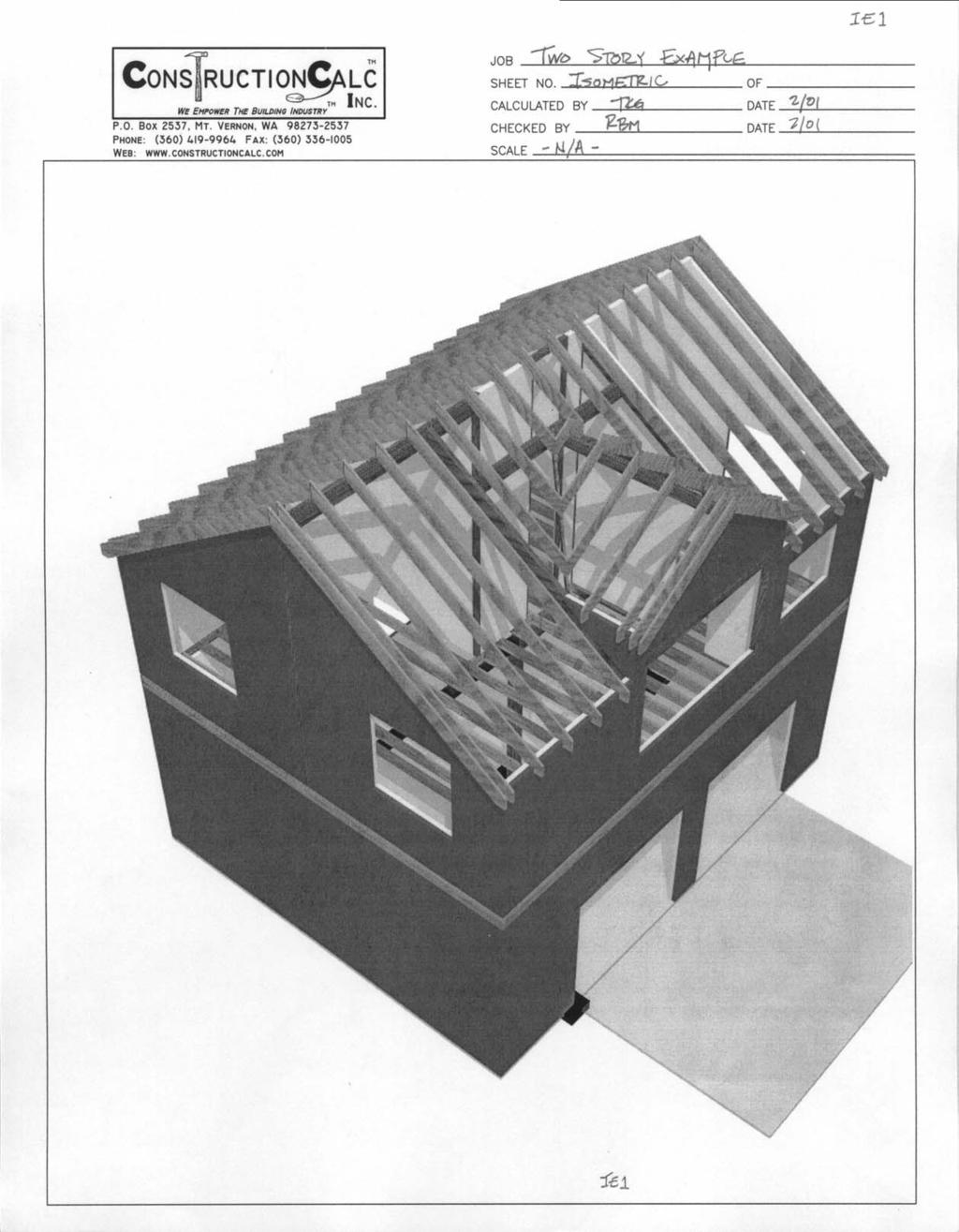
11 Hide (xyz) load sections. Clears all inputs, except pressures in the indicated section then hides that section(s). Use this when you want to minimize the amount of unused information shown. Particularly useful when printing to only show pertinent data. Hide unused loads. This searches for any loading rows that are not being used and then hides them. It is useful when you want to minimize the amount of information displayed, especially when printing. Show (xyz) loads. Unhides previously hidden loading section(s). If the member being designed has complicated loadings, you will want to select this option so that you are able to accurately input all of the loads. Re-size Window. Adjusts the zoom setting so that the program fits within the width of your monitor. This is very helpful to reduce horizontal scrolling. Back to Table of Contents. Returns you to ConstructionCalc s utility program, the Table of Contents. You can select this at any time. Use of this feature does not close the program in use, and applies only if you purchased a ConstructionCalc Software Bundle. Change Background. This allows you to change the look of your sheet by selecting a different background color and / or pattern. 15. Example Problems. Now lets tackle some examples. The next pages show the structure we ll be working on. For the course, we will be designing the members listed below. Two of the other members in the example structure will be quiz questions. The remainder are not addressed in this course. Rafter A Header B Ridge C Valley D Collector E Floor Joist J Header K Beam L (loads from H and F are as shown in the Concentrated Loads section) Several things to be aware of include: Scale. The attached drawings are at ¼ = 1 foot scale. Spans and tributary widths can be scaled directly from a print-out of the elevation and framing plans Live and Dead Loads. Roof dead load corrected for slope is 16 psf. Roof live is 16 psf (from UBC based on pitch). Floor dead is 12 psf and floor live is 40 psf (from UBC for residential floors). Exterior wall dead load is 10 psf and interior wall dead load is 7 psf. CDBJR-11
12 15.3. Snow Load. Regarding snow load, the Uniform Building Code (UBC) requires balanced and unbalanced snow load be considered where appropriate. Unbalanced snow load occurs when snow blows from one side of a roof and accumulates on the other. ConstructionCalc has a program that calculates this automatically which can be purchased from our website, For the purposes of this course, the basic roof snow load for the example problem and the quiz is 35 psf. The unbalanced snow load is 38 psf. In practice, unbalanced snow load applies to any roof bending member that is not a ridge beam (theoretically, a ridge beam experiences the same snow load in the balanced and unbalanced conditions). This concludes the text portion of the course. The following pages show the application of the lecture material. Specific comments and notes are show in caption boxes on each page. * * * Author s Note: These lecture notes are derived from the books, Basic Structural Concepts (for the Non- Engineer) and Basic Structural Bundle User s Manual, both by Tim K. Garrison, P.E. The books are copyrighted and published by ConstructionCalc, Inc and can be purchased in hard copy or pdf format online at CDBJR-12
13 CDBJR-13
14 CDBJR-14
15 CDBJR-15
16 CDBJR-16


17 Following are graphics of the two quiz members, Collector F and Floor Beam M. Collector F Floor Beam M CDBJR-17

18 Wood Beam Calculator Assumptions: Beams are simple span (no overhangs, etc.). Full length of top of beam is laterally supported. No shear stress modifications. Bending in strong axis only. No wet use or high moisture content. No high temperature use. Dynamic loading not considered. Design values from 1997 National Design Specification for Wood Construction. 8/2/2002 Pg. Disclaimer: All users of this software shall comply with State Engineering Law, which specifies who may perform engineering, and defines the practice of engineering. Job Name: Beam I.D.: Other Info.: Two story wood framed example Rafter A Tributary Width Inside to inside, measured horizontally, not along slope. Rafter A General Information Span, L = ft Max. Allowed Live Deflection, L / 360 Max. Allowed Total Deflection, L / 240 Load Duration Two Months (Snow) Dead 0 load already includes 0 self-weight Add Self Wt.? Yes No -100 Loads Other Than Uniform Loads? No Span (ft) Uniform Loads Over Full Length of Member 'psf' loads come from Loads Tributary Uniform Live Reduced Live Unif. Dead Load, Program. Dead load is for Live, psf Dead, psf width, ft Load, plf Load, plf. plf. horizontally Roof projected Loads area, (not and Unused loads including snow) 16 psf 16 psf 2.00 ft lb/ft snow load is for the 'unbalanced are hidden. Roof Snow (only) 38 psf 2.00 ft 76.0 lb/ft 76.0 lb/ft case'. Load Subtotals 76.0 lb/ft 76.0 lb/ft 32.0 lb/ft Total Uniform Loads w L = 76.0 lb/ft w D = 32.0 lb/ft Combined Total Uniform Load w U = lb/ft 4x And Smaller (Lumber) You could choose any 5x And Larger (Timbers) species and grade you Lumber Material Douglas Fir-Larch want. Timber Material Douglas Fir - Larch Lumber Grade No. 2 Timber Grade WCLIB - No. 2 Repetitive 2 x 10 3 x Member Use? (2) 2 x 8 4 x 8 6 x Yes (3) 2 x Logical choices for - - Rafter A. (Ignore the Since rafters are spaced 24" Glued Laminated Members others). 2.0E Parallam PSL or less apart, take advantage Glulam Grade 24F-V4 of 'repetitive member' stress 1-3/4" x 9-1/4" 5-1/4" x 9-1/4" increase. 2-11/16" x 9-1/4" 7" x 9-1/4" 2.5 x x 6 3-1/2" x 9-1/4" 3 x x x x 9 Truss-Joist MacMillan I-Joists 5 x 6 For this example, let's select a DF #2, 2x10 as our final 9-1/2" TJI / Pro /8" TJI / Pro 350 (Applies Only To Western Species Glued-Laminated Beams) choice. 9-1/2" TJI / Pro /8" TJI / Pro 550 Final Member: Reactions - Not Incl. Sefl Wt. Add'l Detail - Not Incl. Self Wt. Sawn Wood R 1 R 2 Max Moment: 1,944 ft-lb Final Size: Live Load: 456 lb 456 lb A 2x10 Member DF #2 exceeds Design Shear: 565 lb 2 x 10 Dead Load: 192 lb 192 lb bending, shear, Total and Deflection: in deflection requirements by Minimum Bearing Total Load: 648 lb 648 lb Live Deflection: in 20%, 79%, and 79% Length = 1.50 in Efficiency of Member: Req'd respectively. EI, no self-weight added 8.865E+07 (Assuming Full-Width Bearing) Bending Overdesign: 20.1% (in^2-lb): Final Member Selected: 2 x 10, Shear Overdesign: 78.9% Approx. Self Weight 0.00 plf Deflection Overdesign:78.6% Min. Calc'd Bearing Length 0.69 in Douglas Fir-Larch, No. 2 This member must have at least 1.5" of bearing length at each end. = 0.40 in = 0.60 in Load (lb/ft) Standard deflection 150 criteria This member makes it by: 20.1% Controlling criteria is: Bending Load and Span Diagram (Not To Scale) These are the downward forces at the ends of Rafter A. They are useful if designing a beam or header that this member bears on. 02ARafter xls

19 Wood Beam Calculator Assumptions: Beams are simple span (no overhangs, etc.). Full length of top of beam is laterally supported. No shear stress modifications. Bending in strong axis only. No wet use or high moisture content. No high temperature use. Dynamic loading not considered. Design values from 1997 National Design Specification for Wood Construction. Disclaimer: All users of this software shall comply with State Engineering Law, which specifies who may perform engineering, and defines the practice of engineering. Job Name: Beam I.D.: Two story wood framed example 1st flr header, K Roof trib width 8/2/2002 Pg. Other Info.: Worst case header Floor trib width. Wall trib width. Header K Load and Span Diagram (Not To Scale) General Information 1,000 Span, L = 8.00 ft 800 Max. Allowed Live Deflection, L / 360 = 0.27 in 600 Max. Allowed Total Deflection, L / 240 = 0.40 in 400 Load Duration 200 Two Months (Snow) 0 Add Self Wt.? Yes No Loads Other Than Uniform Loads? No Span (ft) Uniform Loads Over Full Length of Member A significant Tributary Uniform Live Reduced Live Unif. Dead amount of load Live, psf Dead, psf width, ft Load, plf Load, plf. Load, plf. comes from Roof Loads (not including snow) 16 psf 16 psf 6.50 ft - - snow. Roof Snow (only) 38 psf 6.50 ft lb/ft lb/ft lb/ft Floor Loads 40 psf 12 psf 6.00 ft lb/ft lb/ft 72.0 lb/ft Wall Dead Load 10 psf ft lb/ft We've approximated all loads as uniform loads (roof and wall loads tend to be distributed through rim joist and wall above the window). 4x And Smaller (Lumber) Load (lb/ft) Load Subtotals lb/ft lb/ft lb/ft Total Uniform Loads w L = lb/ft w D = lb/ft Combined Total Uniform Load w U = lb/ft 5x And Larger (Timbers) Lumber Material Lumber Grade Douglas Fir-Larch Timber Material Douglas Fir - Larch No. 2 Timber Grade WCLIB - No. 2 Repetitive - 3 x Member Use? (2) 2 x 14 4 x 12 6 x No (3) 2 x 10 8 x Glued Laminated Members Any time three members together are Glulam shown, Grade 24F-V4 repetitive member credit is automatically 2.5 x x 7.5 included, even if 'No' is selected above. 3 x x x x 9 5 x 7.5 (Applies Only To Western Species Glued-Laminated Beams) 2.0E Parallam PSL 1-3/4" x 9-1/4" 5-1/4" x 9-1/4" 2-11/16" x 9-1/4" 7" x 9-1/4" 3-1/2" x 9-1/4" Truss-Joist MacMillan I-Joists Reactions Including Self-Weight Add'l Detail - Incl. Self Wt. Final Member: Sawn Wood R 1 R 2 Max Moment: 6,448 ft-lb Final Size: Live Load: 1,948 lb 1,948 lb Member Design Shear: 2,603 lb 6 x 10 Dead Load: 1,276 lb 1,276 lb Total Deflection: in Minimum Bearing Total Load: 3,224 lb 3,224 lb Live Deflection: in Length = 1.50 in Efficiency of Member: Req'd EI, no self-weight added 1.827E+08 (Assuming Full-Width Bearing) Bending Overdesign: 2.0% (in^2-lb): Final Member Selected: 6 x 10, Douglas Fir - Larch, WCLIB - No. 2 Shear Overdesign: 27.4% Deflection Overdesign: 153.9% This member makes it by: 2.0% Controlling criteria is: Bending Approx. Self Weight plf Min. Calc'd Bearing Length 0.94 in This member just makes it. Very efficient. 02KHeader xls

20 Wood Beam Calculator Assumptions: Beams are simple span (no overhangs, etc.). Full length of top of beam is laterally supported. No shear stress modifications. Bending in strong axis only. No wet use or high moisture content. No high temperature use. Dynamic loading not considered. Design values from 1997 National Design Specification for Wood Construction. 8/2/2002 Pg. Disclaimer: All users of this software shall comply with State Engineering Law, which specifies who may perform engineering, and defines the practice of engineering. Job Name: Beam I.D.: Other Info.: Two story wood framed example Floor Joist J Trib width Typical floor joist, J General Information Span, L = ft Max. Allowed Live Deflection, L / 480 Max. Allowed Total Deflection, L / 360 Load Duration Ten Years (Live) = 0.30 in = 0.40 in Add Self Wt.? Yes No Loads Other Than Self weight is Uniform Loads? No already in the Note duration dead load. Uniform for floor Loads loads is Over Full Length of Member different than for roof loads. Live, psf Load (lb/ft) Dead, psf Tributary width, ft Uniform Live Load, plf Unif. Dead Load, plf. Floor Loads 40 psf 12 psf 1.33 ft 53.2 lb/ft 53.2 lb/ft 16.0 lb/ft Load Subtotals 53.2 lb/ft 53.2 lb/ft 16.0 lb/ft Total Uniform Loads w L = 53.2 lb/ft w D = 16.0 lb/ft Combined Total Uniform Load w U = 69.2 lb/ft Load and Span Diagram (Not To Scale) Note deflection criteria -40 is for a stiff floor system -60 Span (ft) Reduced Live Load, plf. 4x And Smaller (Lumber) 5x And Larger (Timbers) Lumber Material Lumber Grade Douglas Fir-Larch Timber Material Timber Grade Douglas Fir - Larch No. 2 WCLIB - No. 2 Repetitive 2 x 10 3 x Member Use? (2) 2 x 8 4 x 8 6 x Yes (3) 2 x Glulam Grade Glued Laminated Members 24F-V4 2.5 x x 6 3 x x x x 9 5 x 6 (Applies Only To Western Species Glued-Laminated Beams) Final Member: Reactions - Not Incl. Sefl Wt. Add'l Detail - Not Incl. Self Wt. TJM I-Joist R 1 R 2 Max Moment: 1,245 ft-lb Final Size: Live Load: 319 lb 319 lb Member Design Shear: 415 lb 9-1/2" TJI / Pro 150 Dead Load: 96 lb 96 lb Total Deflection: in Minimum Bearing Total Load: 415 lb 415 lb Live Deflection: in Because we're using a TJM I- Length = Check Manuf. Efficiency of Member: Joist, minimum bearing area is Req'd EI, no self-weight added 8.274E+07 (Assuming Full-Width Bearing) per the manufacturer. Bending Overdesign: 119.3% (in^2-lb): Shear Overdesign: 169.9% Approx. Self Weight 0.00 plf Deflection Overdesign: 69.8% Min. Calc'd Bearing Length N / A Final Member Selected: 9-1/2" TJI / Pro 150, TJM I-Joist This member makes it by: 69.8% Controlling criteria is: Deflection 2.0E Parallam PSL 1-3/4" x 9-1/4" 2-11/16" x 9-1/4" 3-1/2" x 9-1/4" Truss-Joist MacMillan I-Joists 5-1/4" x 9-1/4" 7" x 9-1/4" 9-1/2" TJI / Pro /8" TJI / Pro /2" TJI / Pro /8" TJI / Pro 550 Note this joist easily calcs. We could even increase the trib width to 2' OC and this member would still be okay 02JJoist xls

21 Wood Beam Calculator Assumptions: Beams are simple span (no overhangs, etc.). Full length of top of beam is laterally supported. No shear stress modifications. Bending in strong axis only. No wet use or high moisture content. No high temperature use. Dynamic loading not considered. Design values from 1997 National Design Specification for Wood Construction. Load from Disclaimer: All users of this software shall comply with State Engineering Law, which specifies who may dormer ridge. perform engineering, and defines the practice of engineering. Job Name: Two story wood framed example Collector E Beam I.D.: Collector E Other Info.: Trib width of simplified 'uniform load'. Loads from valleys. 8/2/2002 Pg. General Information Span, L = ft Max. Allowed Live Deflection, L / 360 Max. Allowed Total Deflection, L / 240 Load Duration Add Self Wt.? Yes No Loads Other Than Uniform Loads? Yes Uniform Loads Over Full Length of Member Live, psf Dead, psf Tributary width, ft Uniform Live Load, plf Unif. Dead Load, plf. Roof Loads (not including snow) 16 psf 16 psf 4.25 ft lb/ft Roof Snow (only) 38 psf 4.25 ft lb/ft lb/ft Load Subtotals lb/ft lb/ft 68.0 lb/ft Total Uniform Loads w L = lb/ft w D = 68.0 lb/ft Concentrated (Point) Loads Two Months (Snow) = 0.34 in = 0.52 in 'Simplified uniform load. Load (lb/ft) Combined Total Uniform Load w U = lb/ft Load and Span Diagram (Not To Scale) Span (ft) Reduced Live Load, plf. Sum of point loads. Actual load is two partial wedge loads, but we've conservatively simplified it as a uniform load. Live Load, psf Dead Load, psf Trib. Width, ft. Trib. Length, ft. Live, lbs Dead, lbs Location, ft. Point Load C Descrip'n, opt'l: Ridge C 663 lb 377 lb x C = 5.15 ft Point Load D Descrip'n, opt'l: Valley D 185 lb 86 lb x D = 5.15 ft Point Load E Descrip'n, opt'l: Valley D 185 lb 86 lb x E = 5.15 ft Note: Location Measured From Left Support 4x And Smaller (Lumber) 5x And Larger (Timbers) Lumber Material Lumber Grade Douglas Fir-Larch Timber Material Douglas Fir - Larch No. 2 Timber Grade WCLIB - No. 2 Repetitive - 3 x Member Use? - 4 x 14 6 x No (3) 2 x 12 8 x x 10 - Glued Laminated Members 2.0E Parallam PSL Glulam Grade 24F-V4 1-3/4" x 9-1/2" 5-1/4" x 9-1/4" 2-11/16" x 9-1/4" 7" x 9-1/4" 2.5 x x /2" x 9-1/4" 3 x x x x 9 Truss-Joist MacMillan I-Joists 5 x (Applies Only To Western Species Glued-Laminated Beams) - - Final Member: Reactions Including Self-Weight Add'l Detail - Incl. Self Wt. Sawn Wood R 1 R 2 Max Moment: 7,289 ft-lb Final Size: Live Load: 1,348 lb 1,348 lb Member Design Shear: 1,812 lb (3) 2 x 12 Dead Load: 691 lb 691 lb Total Deflection: in Minimum Bearing Total Load: 2,040 lb 2,040 lb Live Deflection: in Length = 1.50 in Efficiency of Member: Req'd EI, no self-weight added 2.375E+08 (Assuming Full-Width Bearing) Bending Overdesign: 29.2% Shear Overdesign: 103.5% (in^2-lb): Approx. Self Weight plf Deflection Overdesign: 255.9% Min. Calc'd Bearing Length 0.73 in Final Member Selected: (3) 2 x 12, Douglas Fir-Larch, No. 2 This member makes it by: 29.2% Controlling criteria is: Bending 02ECollector xls

22 Wood Beam Calculator Assumptions: Beams are simple span (no overhangs, etc.). Full length of top of beam is laterally supported. No shear stress modifications. Bending in strong axis only. No wet use or high moisture content. No high temperature use. Dynamic loading not considered. Design values from 1997 National Design Specification for Wood Construction. 8/2/2002 Pg. Disclaimer: All users of this software shall comply with State Engineering Law, which specifies who may perform engineering, and defines the practice of engineering. Job Name: Beam I.D.: Other Info.: Two story wood framed example Valley D Valley D General Information Span, L = 7.30 ft Max. Allowed Live Deflection, L / 360 Max. Allowed Total Deflection, L / 240 Load Duration Add Self Wt.? Worst Loads case live Other load Than is unbalanced Uniform snow. Loads? Two Months (Snow) Wedge Loads (Max at Left End, Zero at Right End) Yes Yes No = 0.24 in = 0.37 in Load (lb/ft) Trib width. Measured Load and Span Diagram (Not To Scale) perpendicular to the member being designed (the valley) Span (ft) Comb'd Load, Total Wedge Live Load, psf Dead Load, psf Tributary width, ft Live Load, plf Dead Load, plf plf Load, lb Wedge Load A 38 psf 16 psf 4.00 ft lb/ft 64.0 lb/ft lb/ft 788 lb 4x And Smaller (Lumber) 5x And Larger (Timbers) Lumber Material Lumber Grade Douglas Fir-Larch Timber Material Douglas Fir - Larch No. 2 Timber Grade WCLIB - No. 2 Repetitive 2 x 6 3 x 5 5 x Member Use? (2) 2 x 5 4 x No (3) 2 x Use any member - - shown. Glued Laminated Members 2.0E Parallam PSL Glulam Grade 24F-V4 1-3/4" x 9-1/4" 5-1/4" x 9-1/4" 2-11/16" x 9-1/4" 7" x 9-1/4" 2.5 x x 6 3-1/2" x 9-1/4" 3 x x x x 9 Truss-Joist MacMillan I-Joists 5 x 6 9-1/2" TJI / Pro /8" TJI / Pro 350 (Applies Only To Western Species Glued-Laminated Beams) 9-1/2" TJI / Pro /8" TJI / Pro 550 Final Member: Reactions Including Self-Weight Add'l Detail - Incl. Self Wt. Sawn Wood R 1 R 2 Max Moment: 752 ft-lb Final Size: Live Load: 370 lb 185 lb Member Design Shear: 436 lb 2 x 6 Dead Load: 163 lb 86 lb Total Deflection: in Minimum Bearing Total Load: 533 lb 270 lb Live Deflection: in Length = 1.50 in Efficiency of Member: Req'd EI, no self-weight added 1.999E+07 (Assuming Full-Width Bearing) Bending Overdesign: 12.7% (in^2-lb): Shear Overdesign: 37.7% Approx. Self Weight 2.11 plf Deflection Overdesign:66.4% Min. Calc'd Bearing Length 0.57 in Final Member Selected: 2 x 6, Douglas Fir-Larch, No. 2 This member makes it by: 12.7% Controlling criteria is: Bending 02DValley xls

23 Wood Beam Calculator Assumptions: Beams are simple span (no overhangs, etc.). Full length of top of beam is laterally supported. No shear stress modifications. Bending in strong axis only. No wet use or high moisture content. No high temperature use. Dynamic loading not considered. Design values from 1997 National Design Specification for Wood Construction. 8/2/2002 Pg. Disclaimer: All users of this software shall comply with State Engineering Law, which specifies who may perform engineering, and defines the practice of engineering. Job Name: Beam I.D.: Other Info.: Two story wood framed example Dormer Ridge C Dormer Ridge, 'C' Tributary width. General Information Span, L = 8.50 ft Max. Allowed Live Deflection, L / 360 Max. Allowed Total Deflection, L / 240 Load Duration Two Months (Snow) Add Self Wt.? Yes No Loads Other Than Uniform Loads? No Uniform Loads Over Full Length of Member Live, psf = 0.28 in = 0.43 in Load (lb/ft) Dead, psf Tributary width, ft Uniform Live Load, plf Unif. Dead Load, plf. Roof Loads (not including snow) 16 psf 16 psf 5.20 ft lb/ft Roof Snow (only) 30 psf 5.20 ft lb/ft lb/ft Slope reduced, balanced Snow Load (from Loads program) Load and Span Diagram (Not To Scale) This is the actual load shape. But to 0 simplify the problem, we've assumed the load 5 is uniform, 6 which 7 is always conservative Span (ft) Load Subtotals lb/ft lb/ft 83.2 lb/ft Total Uniform Loads w L = lb/ft w D = 83.2 lb/ft Combined Total Uniform Load w U = lb/ft Reduced Live Load, plf. 4x And Smaller (Lumber) 5x And Larger (Timbers) Lumber Material Lumber Grade Douglas Fir-Larch Timber Material Douglas Fir - Larch No. 2 Timber Grade WCLIB - No. 2 Repetitive 2 x 12 3 x Member Use? (2) 2 x 8 4 x 8 6 x No (3) 2 x Use any member - - shown. Glued Laminated Members 2.0E Parallam PSL Glulam Grade 24F-V4 1-3/4" x 9-1/4" 5-1/4" x 9-1/4" 2-11/16" x 9-1/4" 7" x 9-1/4" 2.5 x x 6 3-1/2" x 9-1/4" 3 x x x x 9 Truss-Joist MacMillan I-Joists 5 x /8" TJI / Pro 350 (Applies Only To Western Species Glued-Laminated Beams) /8" TJI / Pro 550 Final Member: Reactions Including Self-Weight Add'l Detail - Incl. Self Wt. Sawn Wood R 1 R 2 Max Moment: 2,210 ft-lb Final Size: Live Load: 663 lb 663 lb Member Design Shear: 892 lb (2) 2 x 8 Dead Load: 377 lb 377 lb Total Deflection: in Minimum Bearing Total Load: 1,040 lb 1,040 lb Live Deflection: in Length = 1.50 in Efficiency of Member: Req'd EI, no self-weight added 6.610E+07 (Assuming Full-Width Bearing) Bending Overdesign: 23.1% (in^2-lb): Shear Overdesign: 77.5% Approx. Self Weight 5.56 plf Deflection Overdesign:125.4% Min. Calc'd Bearing Length 0.55 in Final Member Selected: (2) 2 x 8, Douglas Fir-Larch, No. 2 This member makes it by: 23.1% Controlling criteria is: Bending 02CDormerRidge xls

24 Wood Beam Calculator Assumptions: Beams are simple span (no overhangs, etc.). Full length of top of beam is laterally supported. No shear stress modifications. Bending in strong axis only. No wet use or high moisture content. No high temperature use. Dynamic loading not considered. Design values from 1997 National Design Specification for Wood Construction. 8/2/2002 Pg. Disclaimer: All users of this software shall comply with State Engineering Law, which specifies who may perform engineering, and defines the practice of engineering. Job Name: Beam I.D.: Other Info.: Two story wood framed example Header B Tributary width. Note, it is actually measured General Information 400 Load and Span Diagram (Not To Scale) horizontally, not along the slope Span, L = 6.00 ft 300 length. Max. Allowed Live Deflection, L / 360 = 0.20 in Max. Allowed Total Deflection, L / 240 = 0.30 in Load Duration Two Months (Snow) Self-wt of this member 0 is not included below Add Self Wt.? Yes No -200 Loads Other Than Uniform Loads? No Span (ft) Uniform Loads Over Full Length of Member Tributary Trib width is half the span 'psf' loads come from Loads Uniform Live Reduced Live Unif. Dead Load, plus the overhang. Program. Dead load is for Live, psf Dead, psf width, ft Load, plf Load, plf. plf. horizontally Roof projected Loads area, (not and including snow) 16 psf 16 psf 6.50 ft lb/ft snow load is for the 'unbalanced Roof Snow (only) 38 psf 6.50 ft lb/ft lb/ft case'. Load Subtotals lb/ft lb/ft lb/ft Total Uniform Loads w L = lb/ft w D = lb/ft Combined Total Uniform Load w U = lb/ft 4x And Smaller (Lumber) You could choose any 5x And Larger (Timbers) species and grade you Lumber Material Douglas Fir-Larch want. Timber Material Douglas Fir - Larch Lumber Grade No. 2 Timber Grade WCLIB - No. 2 Repetitive 2 x 10 3 x Member Use? (2) 2 x 6 4 x 6 6 x No (3) 2 x Use any member - - shown. Since this member 'acts Glued Laminated Members 2.0E Parallam PSL alone', this is 'No'. Glulam Grade 24F-V4 1-3/4" x 9-1/4" 5-1/4" x 9-1/4" 2-11/16" x 9-1/4" 7" x 9-1/4" 2.5 x x 6 3-1/2" x 9-1/4" 3 x x x x 9 Truss-Joist MacMillan I-Joists 5 x /8" TJI / Pro 350 (Applies Only To Western Species Glued-Laminated Beams) /8" TJI / Pro 550 Final Member: Reactions Including Self-Weight Add'l Detail - Incl. Self Wt. Sawn Wood R 1 R 2 Max Moment: 1,602 ft-lb Final Size: Live Load: 741 lb 741 lb Member Design Shear: 905 lb 4 x 6 Dead Load: 327 lb 327 lb Total Deflection: in Minimum Bearing Total Load: 1,068 lb 1,068 lb Live Deflection: in Length = 1.50 in Efficiency of Member: Req'd EI, no self-weight added 3.601E+07 (Assuming Full-Width Bearing) Bending Overdesign: 23.5% (in^2-lb): Shear Overdesign: 55.0% Approx. Self Weight 4.92 plf Deflection Overdesign:115.6% Min. Calc'd Bearing Length 0.49 in Final Member Selected: 4 x 6, Douglas Fir-Larch, No. 2 Load (lb/ft) This member makes it by: 23.5% Controlling criteria is: Bending 02BHeader xls

25 Wood Beam Calculator Assumptions: Beams are simple span (no overhangs, etc.). Full length of top of beam is laterally supported. No shear stress modifications. Bending in strong axis only. No wet use or high moisture content. No high temperature use. Dynamic loading not considered. Design values from 1997 National Design Specification for Wood Construction. Disclaimer: All users of this software shall comply with State Engineering Law, which specifies who may perform engineering, and defines the practice of engineering. Job Name: Beam I.D.: Other Info.: Two story wood framed example Floor Beam L Interior wall trib area = point load. Point load from F Int. wall partial uniform load (roof load not shown). Floor trib width 8/2/2002 Pg. General Information Span, L = ft Max. Allowed Live Deflection, L / 360 Max. Allowed Total Deflection, L / 240 Load Duration Two Months (Snow) Add Self Wt.? Yes No Loads Other Than Uniform Loads? Yes Uniform Loads Over Full Length of Member Live, psf = 0.44 in = 0.67 in Load (lb/ft) Dead, psf Point load from H 2,000 1,500 1, ,000-1,500 Tributary width, ft Int. wall trib area = point Load and Span load. Diagram (Not To Scale) Uniform Live Load, plf Span (ft) Reduced Live Load, plf. Unif. Dead Load, plf. Floor Beam, L Floor Loads 40 psf 12 psf ft lb/ft lb/ft lb/ft Note the loads from a Load Subtotals lb/ft lb/ft lb/ft wall and the left Total Uniform Loads w L = lb/ft w D = lb/ft support of H are so close to this beam's Combined Total Uniform Load w U = lb/ft Concentrated left support, we can (Point) Loads leave them out. Trib. Length, But when we size the Live Load, psf Dead Load, psf Trib. Width, ft. footing and post ft. Live, lbs Dead, lbs Location, ft. below, we must Point Load A 7 psf 6.00 ft ft lb x A = 3.10 ft remember to add them. Point Load B 7 psf 6.00 ft ft lb x B = 3.85 ft Point Load C Descrip'n, opt'l: From H 289 lb 158 lb x C = 3.10 ft Point Load D Descrip'n, opt'l: From F 1,559 lb 807 lb x D = 3.85 ft Note: Location Measured From Left Support Partial Uniform Loads Live Load, psf Dead Load, Comb'd Dead Load, psf Live Load, plf Tributary width, ft plf Load, plf Start Point, ft. End Point, ft. Partial Load A 30 psf 16 psf ft lb/ft lb/ft lb/ft 3.10 ft ft Partial Load B 0 psf 10 psf ft lb/ft lb/ft 3.10 ft ft Note: Start and End Points Measured From Left Support 4x And Smaller (Lumber) 5x And Larger (Timbers) Lumber Material Lumber Grade Douglas Fir-Larch Timber Material Douglas Fir - Larch No. 2 Timber Grade WCLIB - No. 2 Repetitive x 18 - Member Use? x 18 - No - 8 x x x x 18 Glued Laminated Members 2.0E Parallam PSL Glulam Grade 24F-V4-5-1/4" x 14" 2-11/16" x 18" 7" x 11-7/8" x /2" x 16" 3 x x x x 12 Truss-Joist MacMillan I-Joists 5 x (Applies Only To Western Species Glued-Laminated Beams) - - Final Member: Reactions Including Self-Weight Add'l Detail - Incl. Self Wt. Parallam 2.0E PSL R 1 R 2 Max Moment: 35,458 ft-lb Final Size: Live Load: 5,905 lb 5,950 lb Member Design Shear: 9,104 lb 5-1/4" x 14" Dead Load: 3,949 lb 3,817 lb Total Deflection: in Minimum Bearing Total Load: 9,854 lb 9,767 lb Live Deflection: in Length = 2.89 in Efficiency of Member: Req'd EI, no self-weight added1.675e+09 (Assuming Full-Width Bearing) Bending Overdesign: 32.1% Shear Overdesign: 79.5% (in^2-lb): Approx. Self Weight plf Deflection Overdesign: 41.2% Min. Calc'd Bearing Length2.89 in Final Member Selected: 5-1/4" x 14", Parallam 2.0E PSL This member makes it by: 32.1% Controlling criteria is: Bending 02LBeam xls
2) Open ConstructionCalc ProBeam from Microsoft Excel: File Open. 3) Part 1 General Input. Here is a screenshot of Part 1 input.
 Open ConstructionCalc ProBeam from Microsoft Excel: File Open. 3) Part 1 General Input. Here is a screenshot of Part 1 input.") Example Deck Beam Design Using ConstructionCalc ProBeam Software Note: The following example assumes you are a beginner. You should expect this to go slowly at first. However, with a little practice, getting
Example Deck Beam Design Using ConstructionCalc ProBeam Software Note: The following example assumes you are a beginner. You should expect this to go slowly at first. However, with a little practice, getting
2) Open ConstructionCalc ProBeam from Microsoft Excel, then File Open. 3) Part 1 General Input.
 Open ConstructionCalc ProBeam from Microsoft Excel, then File Open. 3) Part 1 General Input.") Example Rafter Design Using ConstructionCalc ProBeam Software Note: The following example assumes you are a beginner. You should expect this to go slowly at first. However, with a little practice, getting
Example Rafter Design Using ConstructionCalc ProBeam Software Note: The following example assumes you are a beginner. You should expect this to go slowly at first. However, with a little practice, getting
Example Hot Tub Deck Design Using ConstructionCalc Software, v2.0
 Example Hot Tub Deck Design Using ConstructionCalc Software, v2.0 Note: The following example assumes you are a beginner. You should expect this to go slowly at first. However, with a little practice,
Combination Roof and Floor Beam Module Walk-Through
 Combination Roof and Floor Beam Module Walk-Through To begin sizing a Combination Roof and Floor Beam in StruCalc you will need to open the Combination Roof and Floor Beam design module. This is done by
LPI 56 Technical Guide
 LPI 56 Technical Guide Floor & Roof Applications Product Specifications & Design Values 2 Floor Tables 3 Uniform Floor Load (PLF) Tables: Simple s 4 Uniform Floor Load (PLF) Tables: Continuous s 5 Uniform
Multi-Span Floor Beam Module Walk-Through
 Multi-Span Floor Beam Module Walk-Through To begin sizing a Multi-Span Floor Beam in StruCalc you will need to open the Multi-Span Floor Beam design module. This is done by one of three ways. The first
CH. 9 WOOD CONSTRUCTION
 CH. 9 WOOD CONSTRUCTION PROPERTIES OF STRUCTURAL LUMBER Grading Load carrying capacity effected by: - Size and number of knots, splits & other defects - Direction of grain - Specific gravity of wood Grading
6.0 TUTORIAL. Cascade Consulting Associates, Inc. PO Box 1617 Corvallis, Oregon 97339
 for WINDOWS TM 6.0 TUTORIAL Cascade Consulting Associates, Inc. PO Box 1617 Corvallis, Oregon 97339 Phone: (541) 753-0117 Fax: (541) 753-9422 www.strucalc.com E-mail: strucalc@strucalc.com 1 1. TUTORIAL
GLOBAL LVL HEADERS, BEAMS AND COLUMNS. 1.9E-2850Fb. 1.9E-2850Fb. User guide User guide. lvlglobal.com
 GLOBAL LVL HEADERS, BEAMS AND COLUMNS 1.9E-2850Fb GLOBAL LVL HEADERS, BEAMS AND COLUMNS 1.9E-2850Fb User guide User guide lvlglobal.com Global LVL, the product of choice for all of your residential, commercial
Featuring Selection and Installation Information for Lateral Wind Loads
 #TJ-8000 SPECIFIER S GUIDE 1¼" TIMBERSTRAND LSL RIM BOARD AND 1 1 8" TJ RIM BOARD Featuring Selection and Installation Information for Lateral Wind Loads For Use in ASCE/SEI 7-05 Basic Wind Speed Regions
Glulam Beam Camber. August 2011
 T E C H N I C A L N O T E Glulam Beam Camber August 2011 One of the most important design qualities of wood framing is its resilience under load. Wood s unique stiffness makes wood floors comfortable to
Fundamentals of Wood Design and Engineering
 Fundamentals of Wood Design and Engineering Session 3 Wood Design Introduction to Wood Engineering; Codes & Standards; Load combinations, weights of building materials and tributary area; Simple beam design:
STRUCTURAL ISSUES IN RESIDENTIAL CONSTRUCTION. Presented by: Susan L. Lasecki P.E., S.E.
 STRUCTURAL ISSUES IN RESIDENTIAL CONSTRUCTION Presented by: Susan L. Lasecki P.E., S.E. Presentation Outline Gravity Design Load Paths from Roof to Foundation Roof Framing Floor Framing Wall Framing Lateral
LUMBER: USE IN CONSTRUCTION
 CHAPTER B2 LUMBER: USE IN CONSTRUCTION This is the most technical chapter in the entire course. But don t let that scare you. Look at it as a challenge. Every time you acquire more knowledge it will help
Wood Shear Wall Design Examples For Wind
 Wood Design Examples For Wind EARN 0.1 ICC Continuing Education Unit (CEU) and/or AIA/CES HSW 1 Learning Unit (LU) DES413-A Wood Design Examples for Wind Description: In this article, a wood frame shear
BROADSPAN. I-Joist Design Brochure. Design properties for I-joist applications in the U.S. for residential floor systems. I-Joist Design Brochure
 BROADSPAN I-Joist Design Brochure Design properties for I-joist applications in the U.S. for residential floor systems I-Joist Design Brochure Product Profiles BSI-400 Series 9¹ ₂ 11⁷ ₈ 14 16 1¹ ₄ -1³
Structural Training - Part 1:
 Structural Training - Part 1: Structural Training Residential Wood-Framed Construction Presented by: City of Santa Clarita Building & Safety Division February, 2014 The information provided in this presentation
2.2E Parallam PSL Deep Beam
 #TJ-7001 SPECIFIER S GUIDE 2.2E Parallam PSL Deep Beam Featuring 20" 24" Deep Trus Joist Parallam PSL Beams Ideal for multi-family and light commercial applications Offers high strength and consistent
LVL Product Guide 2.0E LVL 1.5E LVL
 LVL Product Guide 2.0E LVL 1.5E LVL Our Company Anthony Forest Products Company, a family-owned business founded in 1916, is headquartered in El Dorado, Arkansas. The company operates a southern pine lumber
FIGURE R502.2 FLOOR CONSTRUCTION
 CHAPTER 5 FLOORS 11 I SECTION R501 GENERAL R501.1 Application. The provisions of this chapter shall control the design and construction of the floors for all buildings including the floors of attic spaces
DIVISION: WOOD, PLASTICS AND COMPOSITES SECTION: LAMINATED VENEER LUMBER REPORT HOLDER: REDBUILT LLC EVALUATION SUBJECT:
 0 Most Widely Accepted and Trusted ICC ES Evaluation Report ICC ES 000 (800) 42 6587 (562) 699 054 www.icc es.org ESR 299 Reissued 01/2019 This report is subject to renewal 01/2021. DIVISION: 06 00 00
twelve wood construction: materials & beams ARCHITECTURAL STRUCTURES: FORM, BEHAVIOR, AND DESIGN DR. ANNE NICHOLS SUMMER 2014 lecture
 ARCHITECTURAL STRUCTURES: FORM, BEHAVIOR, AND DESIGN DR. ANNE NICHOLS SUMMER 2014 lecture twelve wood construction: materials & beams Wood Beams 1 Wood Beam Design National Design Specification National
Murphy LVL Limit States Design Guide 2.0 E-LVL 2.2 E-LVL
 Murphy LVL Limit States Design Guide 2.0 E-LVL 2.2 E-LVL Our Company At Murphy Company we take pride in providing our customers with premium quality products and services. Our LVL is manufactured to provide
Allowable Loads for Round Timber Poles
 UNIVERSITY OF ALASKA FAIRBANKS Allowable Loads for Round Timber Poles HCM-00752 UNIVERSITY OF ALASKA FAIRBANKS The following publication is a major upgrade of information for calculating and understanding
twelve wood construction: materials & beams Wood Beam Design Wood Properties Timber National Design Specification
 ARCHITECTURAL STRUCTURES: FORM, BEHAVIOR, AND DESIGN DR. ANNE NICHOLS SUMMER 2017 lecture twelve wood construction: materials & beams Wood Beams 1 Lecture 12 Architectural Structures F2009abn Wood Beam
twelve wood construction: materials & beams Wood Beam Design Wood Properties Timber National Design Specification
 ARCHITECTURAL STRUCTURES: FORM, BEHAVIOR, AND DESIGN DR. ANNE NICHOLS SUMMER 2016 lecture twelve wood construction: materials & beams Wood Beams 1 Lecture 12 Architectural Structures F2009abn Wood Beam
QUIZ 2 Allotted Time: 3 hours
 ARCHITECTURE 324/624: INTRODUCTION TO STRUCTURAL DESIGN PAGE 1 Name print QUIZ 2 Allotted Time: 3 hours On my honor as a student, I pledge the following: I will neither give nor receive unauthorized assistance
twelve wood construction: materials & beams Wood Beam Design Timber Wood Properties National Design Specification
 ARCHITECTURAL STRUCTURES: FORM, BEHAVIOR, AND DESIGN DR. ANNE NICHOLS SUMMER 20178 lecture twelve wood construction: materials & beams Wood Beams 1 Lecture 12 Architectural Structures F2009abn Wood National
OUR COMPANY OUR WARRANTY OUR GUARANTEE
 DESIGN MANUAL-USA FRAMED BY QUALITY BUILT WITH SUCCESS OUR COMPANY At International Beams Inc. we take pride in providing our customers with premium quality products and services. Our full range of engineered
1¾" VERSA-LAM WESTERN HEAdER GuidE
 1¾" VERSA-LAM 1.7 2400 WESTERN HEAdER GuidE for products manufactured in White City, Oregon 11/29/2012 1¾" 1.7 2400 VL Guide 2 VERSA-LAM Products 1¾" VERSA-LAM 1.7 2400 An Introduction to VERSA-LAM Products
Technical Data for. Headers. and Beams
 L A M I N A T E D V E N E E R L U M B E R Technical Data for Headers and Beams E A S T E R N E N G I N E E R E D W O O D P R O D U C T S OUR COMPANY Our total focus on engineered wood products and providing
thirteen wood construction: materials & beams ELEMENTS OF ARCHITECTURAL STRUCTURES: FORM, BEHAVIOR, AND DESIGN DR. ANNE NICHOLS SPRING 2016 lecture
 ELEMENTS OF ARCHITECTURAL STRUCTURES: FORM, BEHAVIOR, AND DESIGN DR. ANNE NICHOLS SPRING 2016 lecture thirteen wood construction: materials & beams Wood Beams 1 Wood Beam Design National Design Specification
2.2E Parallam PSL Deep Beam
 #TJ-7001 SPECIFIER S GUIDE 2.2E Parallam PSL Deep Beam Featuring 20" 24" Deep Trus Joist Parallam PSL Beams Ideal for multi-family and light commercial applications Offers high strength and consistent
Lintels and Beams: Engineering Basis
 Lintels and Beams: Engineering Basis The calculator is intended for the design of lintels and beams in timber- framed buildings generally within the scope of NZS 3604. However, the range of applications,
Method for Increased Buckling Capacity of Built-Up Beams and Columns
 Method for Increased Buckling Capacity of Built-Up Beams and Columns Donald A. Bender, Robert E. Kimble, and Frank E. Woeste Abstract Built-up beams and columns made of dimension lumber fastened with nails,
twelve wood construction: materials & beams Wood Beam Design Wood Properties Timber National Design Specification
 ARCHITECTURAL STRUCTURES: FORM, BEHAVIOR, AND DESIGN DR. ANNE NICHOLS SUMMER 2014 lecture twelve wood construction: materials & beams Wood Beams 1 Lecture 12 Architectural Structures F2009abn Wood Beam
WOOD I-JOIST AWARENESS GUIDE
 WOOD I-JOIST AWARENESS GUIDE American Wood Council Flange Web Flange American Forest & Paper Association WOOD I-JOIST AWARENESS GUIDE The American Wood Council is part of the wood products group of the
Joint Evaluation Report
 0 Joint Evaluation Report ICC ES (800) 423 6587 (562) 699 0543 www.icc es.org 000 ESR 1040 Reissued 09/2018 Revised 03/2019 This report is subject to renewal 09/2019. DIVISION: 06 00 00 WOOD, PLASTICS
thirteen wood construction: materials & beams Timber Wood Beam Design Wood Properties
 ELEMENTS OF ARCHITECTURAL STRUCTURES: FORM, BEHAVIOR, AND DESIGN DR. ANNE NICHOLS SPRING 2018 lecture thirteen wood construction: materials & beams Wood Beams 1 Wood National Design Specification f Wood
PFC-5804* Reissued February 1, Filing Category: DESIGN Wood
 PFC-50* Reissued February 1, 2003 ICBO Evaluation Service, Inc. 530 Workman Mill Road, Whittier, California 9001 www.icboes.org Filing Category: DESIGN Wood PACIFIC WOODTECH CORPORATION PWI JOISTS PACIFIC
Joint Evaluation Report
 0 Joint Evaluation Report ICC-ES (800) 423-6587 (562) 699-0543 www.icc-es.org 000 ESR-1040 Reissued 09/2016 This report is subject to renewal 09/2018. DIVISION: 06 00 00 WOOD, PLASTICS AND COMPOSITES SECTION:
Joint Evaluation Report
 0 Joint Evaluation Report ICC-ES (800) 423-6587 (562) 699-0543 www.icc-es.org 000 ESR-1040 Reissued 09/2018 This report is subject to renewal 09/2019. DIVISION: 06 00 00 WOOD, PLASTICS AND COMPOSITES SECTION:
Streamline Solar Photovoltaic Structural Criteria for Residential Rooftop Solar Energy Installations (Streamline Solar Form 5)
") TOOKIT DOCUMENT #5 Streamline Solar Photovoltaic Structural Criteria for Residential Rooftop Solar Energy Installations (Streamline Solar Form 5) Use of this document This toolkit document includes a one
TOOKIT DOCUMENT #5 Streamline Solar Photovoltaic Structural Criteria for Residential Rooftop Solar Energy Installations (Streamline Solar Form 5) Use of this document This toolkit document includes a one
Building and Safety Division 245 E Bonita Avenue Ph:
 Building and Safety Division 245 E Bonita Avenue Ph: 909-394-6260 E-Mail: solar@ci.san-dimas.ca.us Use of this document Applicants for Expedited Permitting must complete and submit this document in its
SECTION PLATE CONNECTED WOOD TRUSSES
 SECTION 06173 PLATE CONNECTED WOOD TRUSSES PART 1 GENERAL 1.01 SUMMARY A. Section Includes: 1. Shop fabricated wood trusses for roof and floor framing. 2. Bridging, bracing, and anchorage. B. Related Sections:
ICBO Evaluation Service, Inc Workman Mill Road, Whittier, California *Revised April 2003
 PFC-5804* Reissued February 1, 2003 ICBO Evaluation Service, Inc. 5360 Workman Mill Road, Whittier, California 90601 www.icboes.org Filing Category: DESIGN Wood PACIFIC WOODTECH CORPORATION PWI JOISTS
BROADSPAN. LVL Design Brochure. Design properties for LVL header and beam applications in the U.S. for residential floor and roof systems
 BROADSPAN LVL Design Brochure Design properties for LVL header and beam applications in the U.S. for residential floor and roof systems LVL Design Brochure Product Line You ve probably been building with
(b) Calculate the required nominal axial compression strength, Pn of the column.
 Calculate the required nominal axial compression strength, Pn of the column.") 9 Problem 2-3 (a) Determine the factored axial load or the required axial strength, Pu of a column in an office building with a regular roof configuration. The service axial loads on the column are as
9 Problem 2-3 (a) Determine the factored axial load or the required axial strength, Pu of a column in an office building with a regular roof configuration. The service axial loads on the column are as
Structural Criteria for Residential Rooftop Solar Energy Installations
 SWH TOOLKIT DOCUMENT #4 Structural Criteria for Residential Rooftop Solar Energy Installations Use of this document This toolkit document includes a one-page list of structural criteria for over-the-counter
Check the strength of each type of member in the one story steel frame building below.
 CE 331, Summer 2015 nalysis of Steel Braced Frame Bldg 1 / 9 Check the strength of each type of member in the one story steel frame building below. 4 @ 8 ft B 20 f 1 2 3 @ 25 ft Side Elevation 3 4 Plan
Lintels and Beams Engineering basis
 Lintels and Beams Engineering basis The calculator is intended for the design of lintels and beams in timber framed buildings generally within the scope of NZS 3604: 2011 Timber- framed buildings. However
MAX-CORE I-JOIST DESIGN MANUAL-US
 MAX-CORE I-JOIST DESIGN MANUAL-US FRAMED BY QUALITY BUILT WITH SUCCESS OUR COMPANY At International Beams Inc. we take pride in providing our customers with premium quality products and services. Our full
Structural Criteria for Residential Rooftop Solar Energy Installations
 Structural Criteria for Residential Rooftop Solar Energy Installations STEP 3 Expedited Structural Criteria Use of this document This toolkit document includes a list of structural criteria for over-the-counter
Determining Allowable Design Values for Wood
 PDHonline ourse S246 (3 PDH) Determining Allowable Design Values for Wood Instructor: Richard E. Nolan, PE 2012 PDH Online PDH enter 5272 Meadow Estates Drive Fairfax, VA 22030-6658 Phone & Fax: 703-988-0088
2.2E Parallam PSL Deep Beam
 #TJ-7001 SPECIFIER S GUIDE 2.2E Parallam PSL Deep Beam Featuring 20" 24" Deep Trus Joist Parallam PSL Beams Ideal for multi-family and light commercial applications Offers high strength and consistent
Structural Criteria for Residential Rooftop Solar Energy Installations
 Structural Criteria for Residential Rooftop Solar Energy Installations This document applies to flush mounted solar arrays installed on the roofs of wood framed one and two family dwellings. Flush mounted
Whose responsibility is it? Design Responsibility. Steel Joist Institute. Standard Assumptions. Common Pitfalls in Steel Joist Specification
 Common Pitfalls in Steel Joist Specification Whose responsibility is it? Joist supplier? Steel fabricator? Contractor? Other trades? Specifier? Design Responsibility Joist Supplier s responsibilities include
Structural Criteria for Residential Rooftop Solar Energy Installations
 PV TOOLKIT DOCUMENT #5 Structural Criteria for Residential Rooftop Solar Energy Installations Use of this document This toolkit document includes a one-page list of structural criteria for over-the-counter
DIVISION: WOOD, PLASTICS AND COMPOSITES SECTION: WOOD I-JOISTS REPORT HOLDER: PACIFIC WOODTECH CORPORATION
 0 Most Widely Accepted and Trusted ICC-ES Evaluation Report ICC-ES 000 (800) 423-6587 (562) 699-0543 www.icc-es.org ESR-1225 Reissued 10/2017 This report is subject to renewal 10/2019. DIVISION: 06 00
Considerations for Outof-Plane. Design
 Considerations for Outof-Plane Wall and Uplift Design WoodWorks Texas Workshops December, 2016 Overview Uplift Wall Design Wind Loads Wind loads acting on buildings are modeled as uniform surface loads.
Building Division Informational Handout
 CITY OF SAN JOSÉ, CALIFORNIA Building Division Informational Handout Conventional Light Frame Construction Design Provisions 2007 CBC Handout No. 2-21 Published: 1/1/08 Page 1 of 3 This document summarizes
Structural Criteria for Residential Rooftop Solar Energy Installations
 TOOLKIT DOCUMENT #5 Structural Criteria for Residential Rooftop Solar Energy Installations Use of this document This toolkit document includes a one-page list of structural criteria for espedited approval,
2005 ERRATA to the Edition of. the Allowable Stress Design (ASD) Manual for Engineered Wood Construction (printed version dated M)
 Manual for Engineered Wood Construction (printed version dated M)") AMERICAN FOREST & PAPER ASSOCIATION American Wood Council Engineered and Traditional Wood Products June 2005 2005 ERRATA the Allowable Stress Design (ASD) Manual for Engineered Wood Construction 93 In
AMERICAN FOREST & PAPER ASSOCIATION American Wood Council Engineered and Traditional Wood Products June 2005 2005 ERRATA the Allowable Stress Design (ASD) Manual for Engineered Wood Construction 93 In
Maximum Spans Southern Pine Joists & Rafters
 Maximum Spans Southern Pine Joists & Rafters VISUALLY GRADED LUMBER MACHINE STRESS RATED (MSR) MACHINE EVALUATED LUMBER (MEL) www.southernpine.com CONTENTS INDEX TO TABLES Floor and Rafter Framing Diagrams.......
STRUCTURAL EDGE ENGINEERING, PLLC
 JEREMY PARRISH Registered Professional Engineer In Partners with STRUCTURAL EDGE ENGINEERING, PLLC STRUCTURAL EDGE ENGINEERING, PLLC HINES PARK BUILDING A NAMPA, ID SE PROJECT NO: SE16-177 PREPARED FOR:
U.S. WALL GUIDE. Featuring Trus Joist TimberStrand LSL and Parallam PSL Wall Framing. Engineered to meet code requirements for walls up to 30' tall
 #TJ-9003 SPECIFIER S GUIDE U.S. WALL GUIDE Featuring Trus Joist TimberStrand LSL and Parallam PSL Wall Framing Engineered to meet code requirements for walls up to 30' tall Easy-to-use tables adaptable
research report Cold-Formed Steel Gable End Wall Design Using the Prescriptive Method for One and Two Family Dwellings RESEARCH REPORT RP05-2
 research report Cold-Formed Steel Gable End Wall Design Using the Prescriptive Method for One and Two Family Dwellings RESEARCH REPORT RP05-005 REVISION 006 American Iron and Steel Institute Cold-Formed
I-Joist and LVL Installation Guide
 Engineered wood products WOOD The miracle Material Wood is the right choice for a host of construction applications. It is the earth s natural, energy efficient and renewable building material. Engineered
Heel Blocking Requirements and Capacity Analysis. Overview Revised 3/22/2017
 Heel Blocking Requirements and Capacity Analysis Overview Revised 3/22/2017 SBCA has been the voice of the structural building components industry since 1983, providing educational programs and technical
POST AND FRAME STRUCTURES (Pole Barns)
") POST AND FRAME STRUCTURES (Pole Barns) Post and frame structures. The following requirements serve as minimum standards for post and frame structures within all of the following structural limitations:
POST AND FRAME STRUCTURES (Pole Barns) Post and frame structures. The following requirements serve as minimum standards for post and frame structures within all of the following structural limitations:
Trusted WOOD I JOISTS SECTION: 06 ON WEB i. Conformity! ICC-ES Evaluation. Copyright 2015
 0 ICC ES Report ICC ES (800) 42 6587 (562) 699 054 www.icc es.orgg 000 Most Widely Accepted and Trusted ESR 2974 Reissued 07/4 This report is subject to renewal 07/5. DIVISION: 06 00 00 WOOD, PLASTICS
WOOD I BEAM JOISTS PAGE 4 GEORGIA-PACIFIC WOOD PRODUCTS APR 2015 ENGINEERED LUMBER RESIDENTIAL GUIDE
 WOOD I BEAM JOISTS 4 GEORGIA-PACIFIC WOOD PRODUCTS APR 2015 ENGINEERED LUMBER RESIDENTIAL GUIDE Wood I Beam Joist features and benefits Engineered to deliver consistent stiffness and strength characteristics
Framing Methods Structural Components
 Framing Methods Structural Components Balloon Framing *Balloon framing or Eastern framing the exterior studs run from the top of the foundation to the top of the highest level. Benefits of this type of
Dead Load Weight of Roof Trusses. Dead Load Weight of Floor Trusses
 Dead Load Weight of Roof Trusses Top Chord Bottom Chord Webs Weight per Lineal Foot (plf) 2x4 2x4 2x4 4.3 2x4 2x8 2x4 5.6 2x6 2x4 2x4 4.8 2x6 2x6 2x4 5.5 2x6 2x6 2x6 6.2 2x6 2x8 2x4 5.9 2x6 2x10 2x4 6.6
Wood Design for Architects: Engineering for the Non-engineer. AIA Statement
 Wood Design for Architects: Engineering for the Non-engineer AIA Statement The Wood Products Council is a Registered Provider with The American Institute of Architects Continuing Education Systems (AIA/CES).
ACCESSORY STRUCTURE Building permit information For 1 & 2-family dwellings
 ACCESSORY STRUCTURE Building permit information For 1 & 2-family dwellings Building Safety Department 400-2 nd Street South St. Cloud, MN 56301 (320) 255-7239 A building permit is required for any accessory
Structural Criteria for Residential Rooftop Solar Energy Installations
 TOOKIT DOCUMENT #5 Structural Criteria for Residential Rooftop Solar Energy Installations Use of this document This toolkit document includes a one-page list of structural criteria for over-the-counter
Including RedForm LVL, RedForm-I65, I90 and I90H Joists. Lightweight for Fast Installation. Compatible with Standard Framing
 FORMING AND SHORING Including RedForm LVL, RedForm-I65, I90 and I90H Joists Lightweight for Fast Installation Compatible with Standard Framing Available in Long Lengths Uniform and Predictable Resource-efficient
North Shore at Canton Baltimore, MD Beau Menard Technical Report 1
 North Shore at Canton Baltimore, MD Beau Menard Technical Report 1 Structural Schneider 10/05/05 Structural Concepts Executive Summary North Shore at Canton is a 4 story town home and parking garage structure
Structural Criteria for Residential Rooftop Solar Energy Installations
 SWH TOOLKIT DOCUMENT #4 Your City logo here Structural Criteria for Residential Rooftop Solar Energy Installations Use of this document This toolkit document includes a one-page list of structural criteria
Common Errors in Truss Design
 In today s competitive world of trusses, component manufacturers are always looking for ways to generate more efficient truss designs. Occasionally, truss designs need to be changed in order to be sealed
Lateral System Analysis and Confirmation Design November 15, 2004
 Jonathan Hill Structural AE Faculty Consultant Dr. Hanagan Lynde and Harry Bradley School of Technology & Trade Milwaukee, Wisconsin Lateral System Analysis and Confirmation Design November 15, 2004 Executive
GARAGE MAIN FLOOR PLAN
 12'-0" 4'-6" 3'-0" 4'-6" 3040 14'-0" LADDER LT LINE BUNK CABIN 11'-4" x 13'-4" 14'-0" BUILDING CONTRACTOR/HOME OWNER TO REVIEW AND VERIFY ALL DIMENSIONS, SPECS, AND CONNECTIONS BEFORE CONSTRUCTION BEGINS.
CHAPTER 5 FLOORS SECTION R501
 CHAPTER 5 FLOORS SECTION R501 GENERAL R501.1 Application. The provisions of this chapter shall control the design and construction of the floors for all buildings including the floors of attic spaces used
Typical Deck. CONSTRUCTION TIP SHEET 5 Basic Decks w/ 60 lb Live Loading
 CONSTRUCTION TIP SHEET 5 w/ 60 lb Live Loading April 1, 2017 This Tip Sheet reflects code requirements of the 2015 International Residential Code (IRC) with Washington State Amendments which update the
VOLUNTARY - EARTHQUAKE HAZARD REDUCTION IN EXISTING HILLSIDE BUILDINGS (Division 94 Added by Ord. No. 171,258, Eff. 8/30/96.)
") DIVISION 94 VOLUNTARY - EARTHQUAKE HAZARD REDUCTION IN EXISTING HILLSIDE BUILDINGS (Division 94 Added by Ord. No. 171,258, Eff. 8/30/96.) SEC. 91.9401. PURPOSE. (Amended by Ord. No. 172,592, Eff. 6/28/99,
DIVISION 94 VOLUNTARY - EARTHQUAKE HAZARD REDUCTION IN EXISTING HILLSIDE BUILDINGS (Division 94 Added by Ord. No. 171,258, Eff. 8/30/96.) SEC. 91.9401. PURPOSE. (Amended by Ord. No. 172,592, Eff. 6/28/99,
CHAPTER 5 FLOORS SECTION R501
 CHAPTER 5 FLOORS SECTION R501 GENERAL R501.1 Application. The provisions of this chapter shall control the design and construction of the floors for all buildings including the floors of attic spaces used
SPECIFIER GUIDE I-JOISTS. PKI 10, PKI 20, PKI 23, PKI 35 Plus, PKI 40, PKI 50 - CANADA
 SPECIFIER GUIDE I-S PKI 10, PKI 20, PKI 23,, PKI 40, PKI 50 - CANADA PKI 10 SERIES Depths: 9 1/2, 11 7/8, 14 Chord Size: 2 1/2 x 1 1/2 Webstock: 3/8 OSB CCMC # 14001-R UES 431 APA PR-L315C PinkWood manufactures
Joint Evaluation Report ICC-ES (800) (562)
 (562)") 0 Joint Evaluation Report ICC-ES (800) 423-6587 (562) 699-0543 www.icc-es.org 000 ESR-1262 Reissued 01/2018 This report is subject to renewal 01/2019. DIVISION: 06 00 00 DIVISION NAME SECTION: 06 17 33
0 Joint Evaluation Report ICC-ES (800) 423-6587 (562) 699-0543 www.icc-es.org 000 ESR-1262 Reissued 01/2018 This report is subject to renewal 01/2019. DIVISION: 06 00 00 DIVISION NAME SECTION: 06 17 33
BOISE CASCADE - BC FRAMER 3.0 US MAIN FLOOR File Name:
 BOISE CASCADE - BC FRAMER 3.0 US MAIN FLOOR File Name: Y0-0948.bcf 9/30/200 0:37 AM Customer: PRO-BUILD KENNEWICK / JASON Company: BOISE BUILDING MATERIALS DISTRIBUTION Job Name: AHO / 964L City, State:
AdvanTech Sheathing and Subfloor Panels
 AdvanTech Sheathing and Subfloor Panels Load Span Tables AdvanTech wood structural panels are high performance panels designed around 3 performance pillars: 1) superior moisture resistance, 2) superior
LAMINATED VENEER LUMBER
 LAMINATED VENEER LUMBER Kerto LVL Beams, Headers, Rafters and Columns for Floor and Roof Applications. USA VERSION KERTO LAMINATED VENEER LUMBER TABLE OF CONTENTS Design Properties... 2 Allowable Uniform
Due by Friday, March 21, 9:30am(10 Homework Points)
") Winter 2008 - CEE454 Extra Credit Assignment Due by Friday, March 21, 9:30am Due by Friday, March 21, 9:30am(10 Homework Points) The purpose of this assignment is 1) to give you an opportunity to boost
Winter 2008 - CEE454 Extra Credit Assignment Due by Friday, March 21, 9:30am Due by Friday, March 21, 9:30am(10 Homework Points) The purpose of this assignment is 1) to give you an opportunity to boost
DIVISION: WOOD, PLASTICS AND COMPOSITES SECTION: SHOP FABRICATED WOOD TRUSSES REPORT HOLDER: BARRETTE STRUCTURAL DISTRIBUTION, INC.
 0 Most Widely Accepted and Trusted ICC ES Report ICC ES 000 (800) 43 6587 (56) 699 0543 www.icc es.org ESR 999 Reissued 0/07 This report is subject to renewal 0/08. DIVISION: 06 00 00 WOOD, PLASTICS AND
Load Design Charts. R-CONTROL SIPs STRUCTURAL INSULATED PANELS. CONTROL, NOT COMPROMISE.
 R-CONTROL s STRUCTURAL INSULATED PANELS Note: Information deemed reliable at time of printing. Please visit www.r-control.com for latest information. June 2012 CONTROL, NOT COMPROMISE. www.r-control.com
Framing & Building Basics. Architectural Drawing & Interior Design
 Framing & Building Basics Architectural Drawing & Interior Design Introduction to Framing Once you have your floor plan design, you are now ready to plan for building. In order to accomplish this, you
Structural Criteria for Residential Rooftop Solar Energy Installations
 PV TOOLKIT PV TOOLKIT DOCUMENT #5 Structural Criteria for Residential Rooftop Solar Energy Installations Use of this document This toolkit document includes a one-page list of structural criteria for over-the-counter
Structural Criteria for Residential Rooftop Solar Energy Installations
 SWH TOOLKIT DOCUMENT #4 Structural Criteria for Residential Rooftop Solar Energy Installations Use of this document This toolkit document includes a one-page list of structural criteria for over-the-counter
INSTALLATION. US Version. Includes AJS 140 / 150 / 20 / 190 / 25 and VERSA-LAM BEAMS. Lifetime Guaranteed Quality and Performance
 The information in this document pertains to use in the UNITED STATES ONLY, Allowable Stress Design. Refer to the ALLJOIST Specifier Guide Canada for use in Canada, Limit States Design. INSTALLATION Guide
GP LAM LVL WOOD I BEAM JOISTS FIBERSTRONG RIM BOARD. Edition 11. Engineered Lumber product Guide WHAT YOU DON T SEE MATTERS
 GP LAM LVL WOOD I BEAM JOISTS FIBERSTRONG RIM BOARD Edition 11 Engineered Lumber product Guide WHAT YOU DON T SEE MATTERS table of contents WOOD I BEAM JOISTS FIBERSTRONG RIM BOARD GP LAM LVL Wood I Beam