NOTICE. The above identified patent application is available for licensing. Requests for information should be addressed to:
|
|
|
- Garry Hunter
- 6 years ago
- Views:
Transcription
1 «f Serial Number Filing Date Inventor 09/ July 1998 Jon J. Yagla Robert C. Keen NOTICE The above identified patent application is available for licensing. Requests for information should be addressed to: OFFICE OF NAVAL RESEARCH DEPARTMENT OF THE NAVY CODE OOCC ARLINGTON VA ^TA LtS
2 Navy Case INTEGRAL SHIP-WEAPON MODULE STATEMENT OF GOVERNMENT INTEREST The invention described herein may be manufactured and used by or for the Government of the United States of America for governmental purposes without the payment of any royalties thereon or therefor BACKGROUND OF THE INVENTION (1.0) Field of the Invention The present invention relates to a modular launcher for launching missiles, torpedoes, sensors, or counter measures and, more particularly, to a modular launcher that reduces the 10 reinforcement needs of a ship carrying the modular launcher while at the same time reduces the adverse affects commonly caused by the shock of the device being launched. (2.0) Description of the Related Art The primary types of missile launching systems consist of 15 systems that are deck mounted and ones that are enclosed by the vessel, such as built-in launchers enclosed by the hull of the 1
3 ship. The deck mounted launchers either stow the weapons ready to fire in the launcher, or stow the weapons in magazines below or beside the launcher. If the weapons are not stowed ready to fire, machinery is used to load the missiles into the launcher prior to 5 use or to reload after firing. One such launching system fires the weapons from the magazine from within the ship. When the weapons are fired from within the ship, the exhaust gas from the rocket motor has to be conveyed out of the launcher space and discharged into the atmosphere. Exhaust gas management is an important aspect 10 of designing this type of missile launcher. In one such launching system, the exhaust is captured in a plenum chamber under the missiles and then vented out of the plenum through an uptake (chimney). The uptake runs the width of the launcher and a large free area is required to avoid excessive pressure in the plenum and 15 the uptake. Concentric canister launchers, such as those disclosed in U.S. Patent Application Serial No. 08/772,054, now U.S. Patent and its continuation-in-part application U. S. Patent Application Serial No. (Attorney Docket 79081) and both of which are herein incorporated by reference, pass exhaust gas 2 0 through an annular space between the cylinders and avoids excessive pressure in the plenum of the launching system. For existing launching systems foundations are provided in the ship. In one such system, and for rotating arm launchers that load missiles from a magazine space below deck, a relatively large 25 foundation needs to be provided and is located relatively low in
4 the ship. One of the design requirements for launching systems is shock resistance and which has been a difficult design problem for all types of missile launching equipment. Relatively large missile launchers, with equipment foundations very low in the ship, have 5 been especially difficult to design. This is because the shock motions created by underwater explosions are most severe in the keel of the ship. As one moves up and away from the keel, the elastic path associated with shock resistance becomes longer, and the shock advantageously becomes less intense.!0 With all types of weapons installations that penetrate the deck of a ship, great care has to be taken in the design parameters associated with the penetration. Although designing a penetration has to be one of the oldest problems in naval architecture and marine engineering, it still remains a relatively unsolved problem, 15 especially for launching systems. Penetration parameters associated with warship hull-girder design uses the deck of the ship as a primary structural element that is to be penetrated and beam theory is used to design the deck of the ship. The deck of the ship is analogous to flange of an I-beam. When one penetrates 20 or removes a portion of the deck to allow installation of a weapon, such as a launcher system, the bending strength of the deck is greatly compromised. Considerable reinforcement of the deck is required to recover the lost section modulus caused by the penetration. The larger the opening caused by the penetration, the 25 more severe the requirement for reinforcement of the opening
5 becomes, and the more difficult it becomes to maintain the flexural and torsional rigidity of the ship. Stress concentrations around the openings create additional challenges. For example, the mathematical theory of elasticity show that the stress 5 concentration factor around a circular hole in a plate, such as that used for the deck of a ship, is three, i.e., the stress at the hole is three times the stress away from the hole. The size of the hole does not matter, but the shape has an impact. A square hole is much worse than a round hole. The perfectly square hole has 10 theoretical stress concentration of infinity. Therefore, the openings that are basically rectangular, must use radiused corners to reduce stress concentration. Thus, the design problem associated with deck penetrations is two-fold, one must provide sufficient reinforcement to recover the lost section, and then the 15 design must be further refined and detailed to minimize the stress concentrations. When all this is done considerable additional structural mass making up the reinforcements associated with deck penetrations results. When added to the weight of the weapon, there is a concentrated load in this part of the ship having the 2 0 penetrated deck caused by the added launcher, which requires additional design effort, especially when shock loads drive the design process. It is desired to provide a solution that eliminates the bulky reinforcements of conventional penetrations into the deck of a ship, and to reduce stress concentration and 25 foundation motions, both created by the launching of devices from a launching system.
6 OBJECTS OF THE INVENTION It is a primary object of the present invention to provide a launcher that reduces the extent of the reinforcement to a ship that is necessary to accommodate the addition of a launching 5 system. Another object of the present invention is to provide a launching system that reduces stress.concentrations and foundation motions created by the actual launching of devices from the launching system. 10 It is another object of the present invention to provide a launcher comprised of a material that is compensated for stress concentrations. Furthermore, it is an object of the present invention to provide a launching system that is arranged so that it may be 15 easily modified to adapt to the various parameters of different ships that carry different launchable devices. SUMMARY OF THE INVENTION The invention is directed to a modular launching system having concentric members that are arranged to mitigate reinforcement
7 needs of structural members of ships carrying the launching system and to reduce the stresses and movements of the ship's members created by launching devices from the modular launching system. The modular launching system comprises at least one column, at 5 least one plate, at least one baffle and a plurality of collars. The at least one plate is joined to the column and has a plurality of spaced apart cylindrical openings. The at least one baffle is joined to the plate so as to separate the spaced apart cylindrical openings. The plurality of collars are dimensioned to fit into and 10 be joined to the plurality of cylindrical openings. BRIEF DESCRIPTION OF THE DRAWINGS A better understanding of the present invention may be realized when considered in view of the following detailed description, taken in conjunction with the accompanying drawings. 15 Fig. 1 illustrates a modular launcher of the present invention. Fig. 2 is an isometric view of a plurality of modular launchers of Fig. 1 arranged into a row-column matrix forming one embodiment of a modular launching system of the present invention.
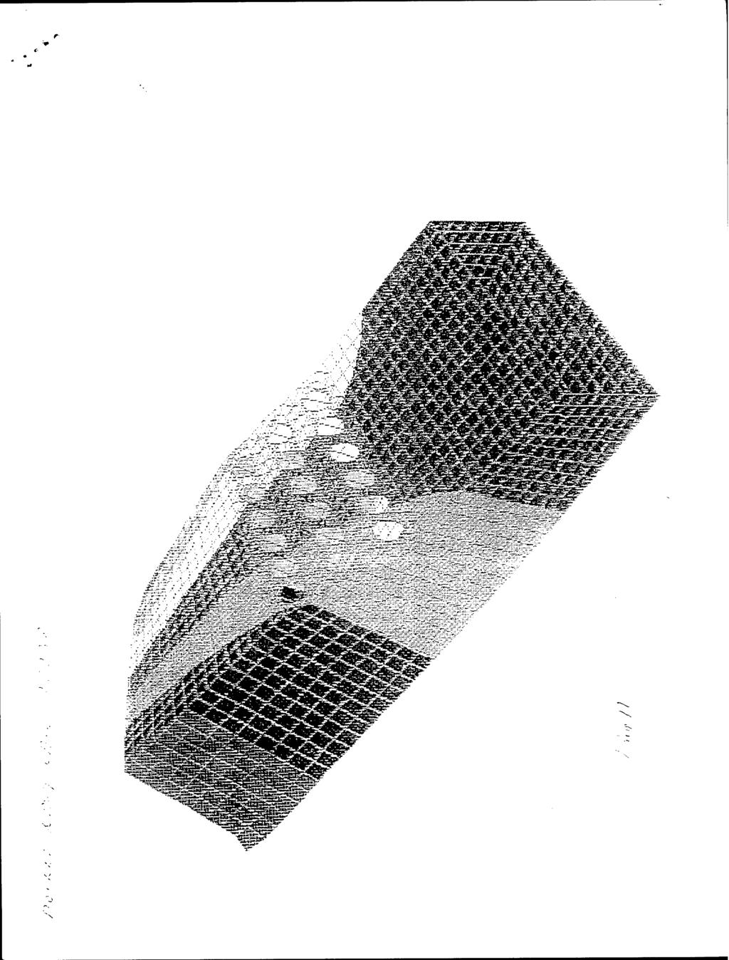
8 Fig. 3 is a top view of the modular launching system of Fig. 2 Fig. 4 is a front view of the modular launching system of Fig. 2 5 Fig. 5 is a side view of the modular launching system of Fig. 2. Fig. 6 illustrates a concentric launcher tube that may serve as one of the columns of the modular launching system of Fig. 2. Fig. 7 is composed of Figs. 7(A) and 7(B) and illustrates a 10 reinforcement arrangement of a prior art launching system. Fig. 8 is composed of Figs. 8(A) and 8(B) and illustrates the reinforcement benefits of the launching system of the present invention. Fig. 9 is a flow chart of the method of the present invention. 15 Figs. 10 and 11 are graphic illustrations related to the installation of Figs. 7 and 8 respectively.
9 DETAILED DESCRIPTION OF PREFERRED EMBODIMENTS Referring to the drawings, wherein the same reference number identifies the same element throughout, there is shown in Fig. 1 a schematic of a modular launcher 10 comprising one embodiment of the 5 present invention. The modular launcher 10 comprises at least one column 12, and at least one plate, but preferably has three plates 14,, 14 2 and 14 3 joined to the column 12 by appropriate means such as a weld 16. Each of the plates 14,, 14 2 and 14 3 has a plurality of spaced apart 10 cylindrical openings 18. The modular launcher 10 has at least one baffle, but preferably two baffles 20, and 20 2 respectively joined to the plates 14, and 14 2 so as to separate the spaced apart cylindrical openings 18 thereon. The modular launcher 10 has a plurality of collars 22 dimensioned to fit into and be joined to 15 the plurality of cylindrical openings 18. Each of the collars 22 has an upper portion 22A and a lower portion 22B. The modular launcher 10 may be arranged into a matrix so as to provide the capabilities of launching multiple launchable devices such as missiles, torpedoes, sensors and countermeasures found aboard a 20 ship and may be further described with reference to Fig. 2. Fig. 2 is an isometric view of a modular launching system 100, wherein the modular launcher 10 of Fig. 2 comprising the plurality of cylindrical openings 18 and collars 22 are arranged into a
10 matrix having row and column elements with the matrix being segmented into groups and with each group being defined by the elements of two rows and two columns of the matrix. As seen in Fig. 2, the modular launching system 100 has a 5 plurality of openings 18 n... 18^ within each of the plates 14,, 14 2 and 14 3 and a plurality of collars 22 n... 22^ fitted into the opening 18 n... 18^ of the plate 14j. As further seen in Fig. 2, and also Fig. 1, each of the columns 12 is associated with one group of openings 18 n 18^ and 10 collars 22 n... 22,^. More particularly, one column 12 is preferably associated with four openings 18 n 18^ and four collars 22 n... 22^. The arrangement of the modular launching system 100 may be further described with reference to Fig. 3 which is a top view thereof. 15 AS seen in Fig. 3, for one embodiment the modular launching system 100 may be arranged into an eight (8) row, ten (10) column matrix so as to support the launching of eighty (80) launchable devices. The modular launching system 100 has a long axis defined by the length spanned by the columns of the matrix. Each of the 20 plates 14 W 14 2 and 14 3 is joined to the column along the long axis. The modular launching system 100 may be further described with reference to Fig. 4 which is a side view, identified by the reference number 24 of Fig. 2.
11 As seen in Fig. 4, each of the plates 14!, 14 2 and 14 3 are joined to each column 12. Each column 12 is preferably formed of a stainless steel type 316. Each column 12 has lower, intermediate, and upper portions and wherein, as seen in Fig. 4, 5 the first (14,), second (14 2 ) and third (14 3 ) plates are respectively joined to the lower, intermediate and upper portions of each of the columns along the long axis of the modular launching system 100. The plates 14,, 14 2 and 14 3 are preferably comprised of steel type A The plates 14, and 14 2 each has baffles 20! and 20 2 separating the cylindrical openings 18 between the rows of the modular launching system 100. The baffles 20, and 20 2 may be further described with reference to Fig. 5 which is a front view, identified by the reference number 26 of Fig AS seen in Fig. 5, plates 14, and 14 2 have pluralities of baffles 20, and 20 2, respectively, that separate the opening 18 n... 18,^. As further seen in Fig. 5, the collars 22 8 i... 22,^, as well as all other collars ^, are joined to the plate 14, and the baffles 20, separate adjacent collars 22 8, 22^ each 2 0 comprised of upper and lower portions 22A and 22B. Each of the collars 22,,... 22^, is preferably comprised of malleable iron. As will be further described with reference to Fig. 6, the modular launching system 100 makes use of round concentric canister 10
12 launchers so as to allow a preferred or optimum shape to provide penetrations so as to minimize the needed reinforcement thereof. The modular launching system 100 allows the fiber stress in the deck of the ship to flow right on through the weapons module. No 5 massive or global reinforcement is required. Should the shock motions need to be minimized, the weapons can be supported at deck level, rather than by foundations near the keel of the ship. This provides an advantageous long elastic path between the keel and the deck. If the weapons are in concentric canisters, the vertical 10 shock loads at the weapons can be reacted at the base of the concentric launcher, advantageously providing additional elastic path so as to further minimize the shock motions created by the launching of launchable devices. If a "shock collar" approach, known in the art, to shock mitigation is used, the weapon reactions 15 at the deck can be greatly reduced. A weapon, that is, a launchable device, lodged in a concentric canister which is beneficial to the present invention may be described with reference to Fig. 6. Fig. 6 illustrates a concentric canister 28 with liquid spring 2 0 shock isolators 3 0 at its lower end and having confined therein a launcher device 28A. The outer casing of the concentric canister 28 may serve as one of the columns 12 of the modular launching system 100 of Figs With reference to Figs. 2 and 4, it is seen that the plates 11
13 14,, 14 2 and 14 3 are longitudinal plates running along the long axis of the modular launching system 100. With reference to Figs. 4 and 5 it is seen that the plates 14,, 14 2 and 14 3 are vertical and run between the rows of the modular 5 launching system 100. The long axis of the modular launching system 100 is aligned with the longitudinal axis (not shown) of the ship. The plates 14,, 14 2 and 14 3 are interchangeably referred to herein as platform level deck plates. With reference to Figs. 2 and 5, it is seen that the columns tie the platform level deck plates 14,, 14 2 and 14 3 together to form a unit structure, that is, the modular launching system 100. If no bottom support, to be further described with reference to Figs. 7 and 8, of the modular launching system 100 is required (or desired), the vertical component of shock motion created by the 15 launching of a launchable device is reacted by the three deck plates 14,, 14 2, and 14 3 and the columns 12. The weather deck level plate, that is, plate 14 3 is most critical, because it has to react to the shock load of all the missiles. The shock mitigation method, which includes the collars 22,,... 22^, is therefore 20 important to the design. Shock mitigation is required to reduce the shock input to the missiles, which usually cannot be expected to survive the shock motions of the ship unless they are protected. There are various means of shock mitigation, known in the art. The critical observation is that the same mitigation that reduces the 12
14 shock load input to the missiles within the modular launching system 100 also reduces the reaction forces at the weather deck If mitigation factors of say four (4) or five (5) can be attained by means known in the art, this is extremely beneficial to the 5 design of the deck, as this is the main load the deck 14 3 must support during shock, and is by far the largest design load for the deck 14 3 in the vertical direction. Shock collars, known in the art, are best for this, because the shock collars mitigate the weight of both the missiles and the canisters within the modular 10 launching system 100. Liguid spring shock isolators, such as those of Fig. 6, between the missile and the canister are second best because they mitigate the weight of the missiles. Some of the benefits of the present invention may be further described with reference to Figs. 7 and Fig. 7 is composed of Figs. 7(A) and 7(B) and, similarly, Fig. 8 is composed of Figs. 8(A) and 8(B), wherein both Figs. 7 and 8 indicate stress flow by the use of directional arrows 32. Fig. 7 illustrates a situation wherein a launcher system is installed in a prior art manner and penetrates three typical decks 3 4A, 3 4B and 20 34C of a ship. Fig. 8 illustrates a situation wherein the modular launcher system 100 is installed and penetrates the same three decks 34A, 34B and 34C of a ship and at which the plates 14,, 14 2 and 14 3 are in respective proximity thereto as shown in Fig. 8. Fig. 7(A) shows a top view of a portion 300 of a ship wherein 13
15 the prior art launching system is represented by a box 302 having rectangular perimeter 3 04 representing the reinforcement provisions, discussed in the "Background" section, necessary to compensate for the structure loss caused by the penetration of the 5 launching system 302 into the decks 34A, 34B and 34C. From Fig. 7(A) it is seen that the stress flow 32 does not penetrate the launching system 3 02, but rather converges and becomes more intense so as to be able to pass around the launching system 302. Fig. 7(B) shows a side view of the portion 300 of a ship 10 wherein the prior art launching system 3 02 has a foundation 3 08 connected to the structure of the ship and generating shock waves indicated by directional arrows 36. The stress flow 32 indicated in Fig. 7(B) is similar to that of Fig. 7(A), that is, the stress flow 3 2 converges so as to flow under and does not flow through the 15 launching system Fig. 8(A) shows a top view of the same portion of the ship of Fig. 7(A), that is, portion 300 and wherein the modular launching system 100 is inserted into and penetrates the same three decks of Fig. 7(B), that is, decks 34A, 34B and 34C. Unlike Fig. 7(A), Fig. 20 8(A) shows the stress flow 34 as advantageously flowing through the modular launching system 100. Fig. 8(B) shows a side view of the portion 300 of a ship, wherein the modular launching system 100 has the same prior art 14
16 foundation 308 as that of Fig. 7(B). However, unlike Fig. 7(B), the stress flow 32 flows through the modular launching system 100 and, more importantly, the stress flow 32 of Fig. 8(B) does not encounter any bending or converging rather it is relatively 5 straight flow through the modular launching system 100. As seen with reference to Fig. 8, the present invention eliminates the bulky reinforcements of a conventional penetration, that is, the present invention does not possess the reinforced perimeter 3 04 that would otherwise accompany the mounting of a 10 prior art launching system into a ship. Further, the present invention reduces stress concentrations because of the relative straight stress flow 3 2 and also reduces severe foundation motions because the stress concentrations are small and localized. Further, shock loads commonly created by stress concentration are 15 reduced by the practice of the present invention. Furthermore, if desired the structure of the modular launching system 100 may be formed by pre-stressed material so as to further compensate for the local stress concentrations which, in turn, has the secondary benefit, at no weight penalty, for advantageously reacting to the 20 shock loads at a much high point in the ship. Moreover, the modular launching system 100 may be a fully stressed part of the receiving ship, rather than a plug-in item such as the launching system 3 02 of Fig. 7, that fits through a heavily reinforced penetration represented by perimeter 3 04 thereof. 15
17 In the practice of the present invention, the cross-section of plate 14, is the principal way in which the cross-section across the cylindrical opening 18 n... 18^ is recovered so as to provide a continuous area moment of inertia about the ship's neutral axis for flexure. The design of the present invention is accomplished in a manner illustrated in Fig. 9 for the method 40 comprised of segments or steps given in Table 1. 16
18 TABLE SEGMENTS GENERAL DESCRIPTION 42 CONVENTIONAL HULL BENDING AND TORSION ANALYSIS WITH DEAD WEIGHT OF WEAPONS, BUT WITHOUT PENETRATION 44 CALCULATE CROSS SECTIONS OF ALL STRUCTURAL MEMBERS IN TRANSVERSE DIRECTION AND DETERMINE TENSILE FORCE IN EACH ELEMENT 46 DEVELOP ROUGH FINITE ELEMENT MODEL OF WEAPON LAUNCHER 48 APPLY TENSILE FORCES ENTERING WEAPON MODULE AS BOUNDARY CONDITIONS TO FINITE ELEMENT MODEL 50 CHECK STRESS IN EACH ELEMENT AGAINST ALLOWABLE STRESS 52 APPLY TORSIONAL MOMENTS TO MODEL 54 REFINE MODEL 56 CHECK STRESS IN EACH ELEMENT AGAINST ALLOWABLE STRESS 58 REFINE MODEL 60 APPLY SHOCK LOADS TO MODEL 62 CHECK STRESS IN EACH ELEMENT AGAINST ALLOWABLE STRESS 64 REFINE MODEL 66 DESIGN COMPLETE In the determination of the needed cross-section of plate 14j one begins, as shown by segment 42 of Fig. 9, by calculating the cross-sectional area of the deck to which plate 14! is to be mated on either end of the modular launching system, assuming no 17
19 penetration into the deck by the modular launching system 100. The deck is designed with an allowable stress, usually 18,000 psi. The allowable bending moment of this deck is then matched by selection of the plate 14, thickness and its thickness and depth of the 5 longitudinal plates 14,, 14 2 and 14 3 running between the rows of the modular launching system 100. These rough calculations are used as a starting point for a finite element analysis of the structure of the modular launching system 100. After the segment 42 of Fig. 9 is complete the method 40 sequences to segment 44. In conjunction 10 with segment 44, segment 46 of developing a finite element model is accomplished. Finite element analysis, such as performed in segment 46, is desired to calculate the needed thickness of plate 14, because the stress concentrations around the round openings cannot be analyzed 15 with a handbook approach or strength of materials approach. After completion of segment 46, as well as segment 44, the method 40 sequences to segment 48. Segment 48 sets up the boundary conditions for the finite element model being used for the weapon launcher 100 and, when 20 complete, the method 40 sequences to element 50. Segment 50 checks the stress in each element of the weapons launching system 100 is within allowable limits, and if YES, sequences to segment 52, but if NO, sequences to segment 54 which 18
20 refines the finite element model originally of segment 46 and then sequences back to segment 48 for the continuation of the method 40. Segment 52 applies torsional moments to the model and sequences to segment 56 which performs in a manner similar to that 5 of segment 50, and if the stress in each element is allowable, segment 56 sequences to segment 60, but if the stress in each element is not allowable, segment 56 sequences to segment 58 which operates in a manner as already described for segment 54. Segment 60 applies shock loads to the model and sequences to 10 segment 62 which performs in a manner similar to segments 50 and 56, and if the stress in each element is allowable, segment 62 sequences to segment 66 and the design is complete, but if the stress in each element is not allowable, segment 62 sequences to segment 64 which operates in a manner as already described for 15 segments 54 and 58. In the practice of this invention, graphic techniques were used to illustrate the differences between the manner of installing a conventional launcher, such as that described with reference to Fig. 7, and that described with reference to Fig. 8 associated with 20 modular launching system 100. The results of these differences are shown by a comparison between Figs. 10 and 11. Figs. 10 and 11 show a finite element model of vessels in 19
21 torsion. The vessels are identical except for the manner of installing the missiles. More particularly, the finite element model of Fig. 10 is associated with installing a launcher system accommodating missiles using the conventional practice, whereas 5 Fig. 11 is a finite element model associated with installing the modular launching system 100 of the present invention accommodating missiles. The conventional reinforced penetration was designed to recover the flexural rigidity of the unpenetrated vessel. The conventional system represented by Fig. 10 is compared against the 10 modular launching system 100 of Fig. 11 both of which meet the same criteria. The conventional penetration shows greater than twice the rotation under a unit torsion load as compared against the modular launching system 100. The weight of the reinforcement for the weapons installation for the modular launching system 100 was 15 half that of the conventional reinforced penetration of the launcher 3 02 of Fig. 7. It should now be appreciated that the modular launching systems of Figs. 1 and 2 reduce the reinforcement needs of a ship carrying the modular launching system while at the same time reduce 2 0 the adverse affects caused by the shock created by the launchable device being launched. While the invention has been described with reference to specific embodiments, the description is illustrative and is not to be construed as limiting the scope of the invention. Various 20
22 modifications and changes may occur to those skilled in the art without departing from the spirit and scope of the invention. 21
23 ABSTRACT OF THE DISCLOSURE A modular launching system is disclosed that reduces the reinforcement needs of mating a launching system to a ship, while at the same time reduces stress concentration and foundation movements created by the modular launching system launching 5 launchable devices. XZ
24 tk v5*»":, \ N "*v T\ "M ~H fn vt- K ^ ( * «s ^ [ *. ^ v ^ $ V >o N N X N * _C'
25
26 * ^
27 'S u ^ V \\ ^ V V H \ ^ v.
28 y s % V \^ ^N ^ ^- "^ \ - \ \ ^-3 ^ \ x^ "J, -.-, L= -^ ' ' -* \ vs O " \ '00 \ - \ \ ^ t^ \ ^.^s ^ ^ -x ^ V X 1 \ ^X ^ \ 1\ r \ o f\ 3 ^
29 :'//): / '/>Jr'?3S SJ h / : /'n >
30 N. N.
31 $
32 $\ ^ II k. * ^ \«> \ Nj 1 S ^ 2 *B - *^ i ^ > Ü 2 o y " c 5 8 g -2 a "2 a w - a o o a 2 s U* M w f\ Zj o 3 o " - ü u ü ~ "51 3 U S C3 ^ > -s o 3 w «C 1=30 «ia o c 3-3 u u o =, l/l o 8 CD "3 n O o> w-,.^s o a s o *^ "? ^ o a, 5 CL ca a c u < > u
33 ^ ^ V ^ \ N
34
The below identified patent application is available for licensing. Requests for information should be addressed to:
 DEPARTMENT OF THE NAVY OFFICE OF COUNSEL NAVAL UNDERSEA WARFARE CENTER DIVISION 1176 HOWELL STREET NEWPORT Rl 02841-1708 IN REPLY REFER TO Attorney Docket No. 300181 24 April 2018 The below identified
Attorney Docket No Date: 6 November 2007
 DEPARTMENT OF THE NAVY NAVAL UNDERSEA WARFARE CENTER DIVISION NEWPORT OFFICE OF COUNSEL PHONE: (401) 832-3653 FAX: (401) 832-4432 NEWPORT DSN: 432-3653 Attorney Docket No. 97966 Date: 6 November 2007 The
The below identified patent application is available for licensing. Requests for information should be addressed to:
 DEPARTMENT OF THE NAVY NAVAL UNDERSEA WARFARE CENTER DIVISION NEWPORT WOFFICE OF COUNSEL (PATENTS) BUILDING 11, CODE OOOC NEWPORT, RHODE ISLAND 02841-1708 PHONE: 401 832-4736 FAX: 401 832-1231 DSN: 432-4736
DISTRIBUTION STATEMENT A Approved for Public Release Distribution Unlimited
 Serial Number Filing Date Inventor 08/95.994 9 September 1997 Eugene E. Nolting Jon Colfield Roy Richard Steven Peterson NOTICE The above identified patent application is available for licensing. Requests
Appendix M 2010 AASHTO Bridge Committee Agenda Item
 Appendix M 2010 AASHTO Bridge Committee Agenda Item 2010 AASHTO BRIDGE COMMITTEE AGENDA ITEM: SUBJECT: LRFD Bridge Design Specifications: Section 5, High-Strength Steel Reinforcement TECHNICAL COMMITTEE:
DEPARTMENT OF THE NAVY DIVISION NEWPORT OFFICE OF COUNSEL PHONE: FAX: DSN:
 MAl/SE/K WARFARE CENTERS NEWPORT DEPARTMENT OF THE NAVY NAVAL UNDERSEA WARFARE CENTER DIVISION NEWPORT OFFICE OF COUNSEL PHONE: 401 832-3653 FAX: 401 832-4432 DSN: 432-3653 Attorney Docket No. 96155 Date:
IN THE APPLICATION INVENTOR(S) ABUL KALAM AZAD AND IBRAHIM YAHYA AHMED HAKEEM FOR ULTRA-HIGH PERFORMANCE CONCRETE REINFORCEMENT BARS
 ABUL KALAM AZAD AND IBRAHIM YAHYA AHMED HAKEEM FOR ULTRA-HIGH PERFORMANCE CONCRETE REINFORCEMENT BARS") Attorney Docket No. 4000.4 IN THE APPLICATION OF INVENTOR(S) ABUL KALAM AZAD AND IBRAHIM YAHYA AHMED HAKEEM FOR ULTRA-HIGH PERFORMANCE CONCRETE REINFORCEMENT BARS APPLICANT: King Fahd University of Petroleum
Attorney Docket No. 4000.4 IN THE APPLICATION OF INVENTOR(S) ABUL KALAM AZAD AND IBRAHIM YAHYA AHMED HAKEEM FOR ULTRA-HIGH PERFORMANCE CONCRETE REINFORCEMENT BARS APPLICANT: King Fahd University of Petroleum
Structural Design of a Containership Approximately 3100 TEU According to the Concept of General Ship Design B-178
 Structural Design of a Containership Approximately 3100 TEU According to the Concept of General Ship Design B-178 W.Souadji, Zbigniew Sekulski, B.Hamoudi 1 Abstract The design developed in this work is
Field and Laboratory Performance of FRP Bridge Panels
 Field and Laboratory Performance of FRP Bridge s D. Stone, A. Nanni, & J. Myers University of Missouri Rolla, Rolla, Missouri, USA ABSTRACT: The objective of this research project is to examine the use
Introduction to Structural Analysis TYPES OF STRUCTURES LOADS AND
 AND Introduction to Structural Analysis TYPES OF STRUCTURES LOADS INTRODUCTION What is the role of structural analysis in structural engineering projects? Structural engineering is the science and art
Half through bridges No. 1.10
 Half through bridges Scope This Guidance Note describes the structural action and typical applications of this type of bridge. Aspects requiring particular attention are identified. Basic form and structural
Level 6 Graduate Diploma in Engineering Structural analysis
 9210-111 Level 6 Graduate Diploma in Engineering Structural analysis Sample Paper You should have the following for this examination one answer book non-programmable calculator pen, pencil, ruler, drawing
CADS A3D MAX. How to model shear walls
 CADS A3D MAX How to model shear walls Modelling shear walls in A3D MAX Introduction and synopsis This paper explains how to model shear walls in A3D MAX using the `wide column rigid arm sub-frame described
Modeling stiffener distortion in orthotropic bridge decks with FEM using superelements
 Modeling stiffener distortion in orthotropic bridge decks with FEM using superelements C. Delesie 1 & P. Van Bogaert 1 1 Civil engineering department, Ghent university, Ghent,Belgium ABSTRACT: Modern design
Question Paper Code : 11410
 Reg. No. : Question Paper Code : 11410 B.E./B.Tech. DEGREE EXAMINATION, APRIL/MAY 2011 Fourth Semester Mechanical Engineering ME 2254 STRENGTH OF MATERIALS (Common to Automobile Engineering and Production
A Practical Guide to Free Energy Devices
 A Practical Guide to Free Energy Devices Part PatE3: Last updated: 28th January 2006 Author: Patrick J. Kelly Please note that this is a re-worded excerpt from this patent. It describes how to burn the
Steel Design Guide Series. Steel and Composite Beams with. Web Openings
 Steel Design Guide Series Steel and Composite Beams with Web Openings Steel Design Guide Series Steel and Composite Beams with Web Openings Design of Steel and Composite Beams with Web Openings David Darwin
10-COLUMNS: 10.1 Introduction.
 1 10-COLUMNS: 10.1 Introduction. Columns are vertical compression members of a structural frame intended to support the loadcarrying beams. They transmit loads from the upper floors to the lower levels
Leelachai M, Benson S, Dow RS. Progressive Collapse of Intact and Damaged Stiffened Panels.
 Leelachai M, Benson S, Dow RS. Progressive Collapse of Intact and Damaged Stiffened Panels. In: 5th International Conference on Marine Structures (MARSTRUCT). 2015, Southampton, UK: CRC Press. Copyright:
AREMA 2008 Annual Conference. LOW PROFILE RAILROAD BRIDGE Steve K. Jacobsen, PE NNW, Inc. Rochester, Minnesota
 AREMA 2008 Annual Conference LOW PROFILE RAILROAD BRIDGE Steve K. Jacobsen, PE NNW, Inc. Rochester, Minnesota 55904 507-281-5188 Steve K. Jacobsen, PE 2 LOW PROFILE RAILROAD BRIDGE Steve K. Jacobsen, PE
The below identified patent application is available for licensing. Requests for information should be addressed to:
 DEPARTMENT OF THE NAVY OFFICE OF COUNSEL NAVAL UNDERSEA WARFARE CENTER DIVISION 1176 HOWELL STREET NEWPORT Rl 02841-1708 IN REPLY REFER TO Attorney Docket No. 300139 15 December 2017 The below identified
Comparing Fire Response of Simulated Rocket Motors in Steel and Carbon Fiber Composite Missile Launching Canisters
 Comparing Fire Response of Simulated Rocket Motors in Steel and Carbon Fiber Composite Missile Launching Canisters Jon J. Yagla, PhD. Insensitive Munitions and Energetic Materials Technology Symposium
United States Patent (19) Bonacci
 Bonacci") United States Patent (19) Bonacci USOO5934.800A 11 Patent Number: (45) Date of Patent: Aug. 10, 1999 54 PORTABLE CEMENT MIXER AND METHOD 76 Inventor: Anthony S. Bonacci, 217 Fifth Ave., West Mifflin, Pa.
United States Patent (19) Bonacci USOO5934.800A 11 Patent Number: (45) Date of Patent: Aug. 10, 1999 54 PORTABLE CEMENT MIXER AND METHOD 76 Inventor: Anthony S. Bonacci, 217 Fifth Ave., West Mifflin, Pa.
Code No: R Set No. 1
 Code No: R059210303 Set No. 1 II B.Tech I Semester Regular Examinations, November 2006 MECHANICS OF SOLIDS ( Common to Mechanical Engineering, Mechatronics, Metallurgy & Material Technology, Production
Compressive strength of double-bottom under alternate hold loading condition
 Compressive strength of double-bottom under alternate hold loading condition J.M. Gordo CENTEC, IST, University of Lisbon, Portugal ABSTRACT: The alternate bending of the bottom structure of a ship as
Morgan 45 Date of Patent: Sep. 23, 1997
 US005669079A United States Patent (19) 11 Patent Number: 5,669,079 Morgan 45 Date of Patent: Sep. 23, 1997 54 SAFETY ENHANCED MOTORCYCLE 4,432,099 2/1984 Gricket al.... 2/414 HELMET 4,586,200 5/1986 Poon...
SET PROJECT STRUCTURAL ANALYSIS OF A TROUGH MODULE STRUCTURE, IN OPERATION AND EMERGENCY Luca Massidda
 SET PROJECT STRUCTURAL ANALYSIS OF A TROUGH MODULE STRUCTURE, IN OPERATION AND EMERGENCY Luca Massidda Table of Contents Introduction... 2 Finite element analysis... 3 Model description... 3 Mirrors...
58 Field of Search /540,583, direction, and are moved rapidly onto a selected one of a
 USOO5887699A United States Patent (19) 11 Patent Number: 5,887,699 Tharpe (45) Date of Patent: Mar. 30, 1999 54 SYSTEM AND METHOD FOR CONVEYING 3,645,391 2/1972 Hirakawa et al.... 209/583 X AND SORTING
How Beams Work, I. Statics and Strength of Materials
 How Beams Work, I Statics and Strength of Materials HOW BEAMS WORK Beams work by transferring transverse loads along their length to their supports primarily by resisting a force called internal bending
UNIT I SIMPLE STRESSES AND STRAINS, STRAIN ENERGY
 SIDDHARTH GROUP OF INSTITUTIONS :: PUTTUR Siddharth Nagar, Narayanavanam Road 517583 QUESTION BANK (DESCRIPTIVE) Subject with Code: Year & Sem: II-B.Tech & I-Sem Course & Branch: B.Tech - ME Regulation:
(12) Patent Application Publication (10) Pub. No.: US 2010/ A1
 Patent Application Publication (10) Pub. No.: US 2010/ A1") (19) United States US 20100146890A1 (12) Patent Application Publication (10) Pub. No.: US 2010/0146890 A1 Kristensen (43) Pub. Date: Jun. 17, 2010 (54) FOUNDATION FOR ENABLING ANCHORING OFA WIND TURBINE
(19) United States US 20100146890A1 (12) Patent Application Publication (10) Pub. No.: US 2010/0146890 A1 Kristensen (43) Pub. Date: Jun. 17, 2010 (54) FOUNDATION FOR ENABLING ANCHORING OFA WIND TURBINE
March 9, J. B. williamson 2,073,358 SELF SUPPORTING TANK ROOF.
 March 9, 1937. J. B. williamson 2,073,8 SELF SUPPORTING TANK ROOF. Filed March 22, 19 3. Sheets-Sheet 1 X S. as N,. inventor /277zes A. Wz7/ea resort BY..... Attorney March 9, 1937. J. B. WILLIAMSON 2,073,8
Compressive strength of double-bottom under alternate hold loading condition
 Progress in the Analysis and Design of Marine Structures Guedes Soares & Garbatov (Eds) 017 Taylor & Francis Group, London, ISBN 978-1-138-06907-7 Compressive strength of double-bottom under alternate
SIDDHARTH GROUP OF INSTITUTIONS :: PUTTUR Siddharth Nagar, Narayanavanam Road QUESTION BANK (DESCRIPTIVE)
") SIDDHARTH GROUP OF INSTITUTIONS :: PUTTUR Siddharth Nagar, Narayanavanam Road 517583 QUESTION BANK (DESCRIPTIVE) Subject with Code :Strength of Materials-II (16CE111) Course & Branch: B.Tech - CE Year
SIDDHARTH GROUP OF INSTITUTIONS :: PUTTUR Siddharth Nagar, Narayanavanam Road 517583 QUESTION BANK (DESCRIPTIVE) Subject with Code :Strength of Materials-II (16CE111) Course & Branch: B.Tech - CE Year
Downloaded from MILITARY STANDARD
 INCH-POUND MIL-STD-2189 (SH) 22 JANUARY 1988 MILITARY STANDARD DESIGN METHODS FOR NAVAL SHIPBOARD SYSTEMS REINFORCEMENT OF OPENINGS IN STRUCTURE OF SURFACE SHIPS OTHER THAN IN PROTECTIVE PLATING AMSC N/A
Flexure and Serviceability Limit State
 UNIT 3 Flexure and Serviceability Limit State Beam A structural member that support transverse (Perpendicular to the axis of the member) load is called a beam. Beams are subjected to bending moment and
WYDZIAtUARCHiTE TORY WELDED STEEL CONSTRUCTIONS IN POLAND IN 1934.
 0 1 D L J 0 T EZ K A WYDZIAtUARCHiTE TORY P_p li t P r. h r,,;, i ijtgg n ^ s k i e j /g? WELDED STEEL CONSTRUCTIONS IN POLAND IN 1934. BY STEFAN BRYfcA, C.E., D.ENO. (PROFESSOR AT THE TECHNICAL COLLEGE
Investigation of Negative Moment Reinforcing in Bridge Decks
 Tech Transfer Summaries Institute for Transportation 9-2015 Investigation of Negative Moment Reinforcing in Bridge Decks Brent Phares Institute for Transportation, bphares@iastate.edu Sameera Jayathilaka
Conventional Paper II (a) Draw a crank rocker mechanism and identify all instantaneous centers.
 Draw a crank rocker mechanism and identify all instantaneous centers.") Conventional Paper II-2014 1. Answer of the following (Each part carries 4 marks): (a) Draw a crank rocker mechanism and identify all instantaneous centers. (b) A steel tube 2.5 cm external diameter and
Conventional Paper II-2014 1. Answer of the following (Each part carries 4 marks): (a) Draw a crank rocker mechanism and identify all instantaneous centers. (b) A steel tube 2.5 cm external diameter and
(51) Int Cl.: G10K 11/16 ( ) E02D 27/42 ( ) E04B 1/98 ( ) F16F 15/02 ( ) F16F 15/06 ( )
 Int Cl.: G10K 11/16 ( ) E02D 27/42 ( ) E04B 1/98 ( ) F16F 15/02 ( ) F16F 15/06 ( )") (19) TEPZZ 889877A_T (11) EP 2 889 877 A1 (12) EUROPEAN PATENT APPLICATION (43) Date of publication: 01.07.20 Bulletin 20/27 (21) Application number: 14194009.8 (1) Int Cl.: GK 11/16 (2006.01) E02D 27/42
(19) TEPZZ 889877A_T (11) EP 2 889 877 A1 (12) EUROPEAN PATENT APPLICATION (43) Date of publication: 01.07.20 Bulletin 20/27 (21) Application number: 14194009.8 (1) Int Cl.: GK 11/16 (2006.01) E02D 27/42
Comparison of One-way and Two-way slab behavior. One-way slabs carry load in one direction. Two-way slabs carry load in two directions.
 Two-way Slabs Comparison of One-way and Two-way slab behavior One-way slabs carry load in one direction. Two-way slabs carry load in two directions. Comparison of One-way and Two-way slab behavior One-way
1. Name the various sources of stress concentration in machine elements.
 TWO MARKS QUESTIONS 1. Name the various sources of stress concentration in machine elements. 2. What is meant by resilience of a body? 3. What are the factors to be considered for the selection of materials
Fast Cook-Off Modeling and Simulation
 Fast Cook-Off Modeling and Simulation Jon J. Yagla and Saul Hernandez-Valle Paper No. 20259 Gun and Electric Weapon Systems (E) NSWCDD-PN-18-00170; Distribution Statement A: Approved for Public Release;
Two-way slabs. Flat plate with or without drop panels / capitals
 Two-way slabs Two-way slab behavior is described by plate bending theory which is a complex extension of beam bending. Codes of practice allow use of simplified methods for analysis and design of two-way
Introduction. Crossarm Design
 SUBJECT BCTC 287kV H-Frame Crossarm Finite Element Analysis Report AUTHOR Jeremy Mostoller DATE August 4, 2008 Introduction This report details the analysis and optimization of the glass fiber reinforced
Journal of Asian Scientific Research EVALUATION OF RECTANGULAR CONCRETE-FILLED STEEL-HOLLOW SECTION BEAM-COLUMNS
 Journal of Asian Scientific Research journal homepage: http://www.aessweb.com/journals/5003 EVALUATION OF RECTANGULAR CONCRETE-FILLED STEEL-HOLLOW SECTION BEAM-COLUMNS Kamyar Bagherinejad 1 ---- Emad Hosseinpour
ST7008 PRESTRESSED CONCRETE
 ST7008 PRESTRESSED CONCRETE QUESTION BANK UNIT-I PRINCIPLES OF PRESTRESSING PART-A 1. Define modular ratio. 2. What is meant by creep coefficient? 3. Is the deflection control essential? Discuss. 4. Give
M. Bruneau 1, Y. Alzeni 2, P. Fouché 2
 Steel Innovations Conference 2013 Christchurch, New Zealand 21-22 February 2013 SEISMIC BEHAVIOR OF CONCRETE-FILLED STEEL SANDWICH WALLS AND CONCRETE-FILLED STEEL TUBE COLUMNS M. Bruneau 1, Y. Alzeni 2,
(a) Pin-Pin P cr = (b) Fixed-Fixed P cr = (d) Fixed-Pin P cr =
 Pin-Pin P cr = (b) Fixed-Fixed P cr = (d) Fixed-Pin P cr =") 1. The most critical consideration in the design of rolled steel columns carrying axial loads is the (a) Percent elongation at yield and the net cross-sectional area (b) Critical bending strength and axial
1. The most critical consideration in the design of rolled steel columns carrying axial loads is the (a) Percent elongation at yield and the net cross-sectional area (b) Critical bending strength and axial
Section A A: Slab & Beam Elevation
 CE 331, Spring 2011 Flexure Strength of Reinforced Concrete s 1 / 5 A typical reinforced concrete floor system is shown in the sketches below. The floor is supported by the beams, which in turn are supported
ISSUE A Code Change # 2 Class 3 and Class 4 Buildings
 ISSUE A Code Change # 2 Class 3 and Class 4 Buildings (new) Section 1604.9 Disproportionate Collapse. Design for structural integrity of new buildings to protect against disproportionate collapse shall
Load capacity rating of an existing curved steel box girder bridge through field test
 109 Dongzhou Huang Senior Engineer IV TS Transportation Design South Florida Atkins North America Load capacity rating of an existing curved steel box girder bridge through field test Abstract This paper
RESILIENT INFRASTRUCTURE June 1 4, 2016
 RESILIENT INFRASTRUCTURE June 1 4, 2016 MOMENT REDISTRIBUTION OF GFRP-RC CONTINUOUS T-BEAMS S. M. Hasanur Rahman M.Sc. Student, University of Manitoba, Canada Ehab El-Salakawy Professor and CRC in Durability
Spatial analysis of concrete filled steel tubular tied arch bridge
 Spatial analysis of concrete filled steel tubular tied arch bridge W. Huang College of Traffic, Fujian Agriculture and Forestry University, Fujian, China B. Chen College of Civil Engineering, Fuzhou University,
MACHINES DESIGN SSC-JE STAFF SELECTION COMMISSION MECHANICAL ENGINEERING STUDY MATERIAL MACHINES DESIGN
 1 SSC-JE STAFF SELECTION COMMISSION MECHANICAL ENGINEERING STUDY MATERIAL C O N T E N T 2 1. MACHINE DESIGN 03-21 2. FLEXIBLE MECHANICAL ELEMENTS. 22-34 3. JOURNAL BEARINGS... 35-65 4. CLUTCH AND BRAKES.
CHAPTER III DYNAMIC BEHAVIOR OF A LABORATORY SPECIMEN
 CHAPTER III DYNAMIC BEHAVIOR OF A LABORATORY SPECIMEN To address the vibration response of a long span deck floor system, an experiment using a specimen that resembles the conditions found in the in-situ
SPECIFICATIONS FOR THE CONSTRUCTION OF NEW PASSENGER EQUIPMENT CARS PREFACE
 SPECIFICATIONS FOR THE CONSTRUCTION OF NEW PASSENGER EQUIPMENT CARS Standard ADOPTED 1939; ADVANCED TO STANDARD, 1945. PREFACE The specifications have been prepared on the basis that they will be used
FE Review Mechanics of Materials
 1 2 3 4 5 6 7 8 9 10 11 12 13 14 15 16 17 18 19 20 21 22 23 24 25 26 27 28 29 1. T he element is subjected to the plane stress condition shown. a-x = - 140 M Pa a- y = 205 M Pa Txy = 100 M Pa What is t
ME 207 Material Science I
 ME 207 Material Science I Chapter 4 Properties in Bending and Shear Dr. İbrahim H. Yılmaz http://web.adanabtu.edu.tr/iyilmaz Automotive Engineering Adana Science and Technology University Introduction
9. VACUUM TANK 9. VACUUM TANK
 9. VACUUM TANK This system constitutes the external part of the solenoid cryostat. The vacuum tank, made of stainless steel, is cantilevered from the central ring of the barrel yoke. It houses and supports
One-Way Wide Module Joist Concrete Floor Design
 One-Way Wide Module Joist Concrete Floor Design A 1 3 4 30'-0" 30'-0" 30'-0" 3' B 3' C 3' D 3' E 4" 4" (typ.) 3' F 0" 0" (typ.) Figure 1 One-Way Wide Module Joist Concrete Floor Framing System 1 Overview
TMR 4195 DESIGN OF OFFSHORE STRUCTURES. Problem 1. In the ULS control it is necessary to consider the load cases given in Table 1.
 NTNU Faculty of Engineering Science and Technology Department of Marine Technology SOLUTION 4 & 5 TMR 4195 DESIGN OF OFFSHORE STRUCTURES Problem 1 In the ULS control it is necessary to consider the load
RESILIENT INFRASTRUCTURE June 1 4, 2016
 RESILIENT INFRASTRUCTURE June 1 4, 2016 OPTIMIZATION OF A POLYGONAL HOLLOW STRUCTURAL STEEL SECTION IN THE ELASTIC REGION John Samuel Kabanda PhD candidate, Queen s University, Canada Colin MacDougall
MIDAS Training Series
 MIDAS midas Civil Title: All-In-One Super and Sub Structure Design NAME Edgar De Los Santos / MIDAS IT United States 2016 Substructure Session 1: 3D substructure analysis and design midas Civil Session
IIII. United States Patent (19) Smith 108/56.1; 211/189, 182, 195. preferably rectangular in shape and the support frame has
 Smith 108/56.1; 211/189, 182, 195. preferably rectangular in shape and the support frame has") United States Patent (19) Smith 54. STORAGE/SHIPPING RACK FOR FENCE SECTION 76) Inventor: Lee Roy Smith, 110 Two Rivers Ct., Nashville, Tenn. 37214 21 Appl. No.: 526,549 22 Filed: Sep. 12, 1995 (51) Int.
United States Patent (19) Smith 54. STORAGE/SHIPPING RACK FOR FENCE SECTION 76) Inventor: Lee Roy Smith, 110 Two Rivers Ct., Nashville, Tenn. 37214 21 Appl. No.: 526,549 22 Filed: Sep. 12, 1995 (51) Int.
SIMPLE INVESTIGATIONS OF TENSILE MEMBRANE ACTION IN COMPOSITE SLABS IN FIRE
 SIMPLE INVESTIGATIONS OF TENSILE MEMBRANE ACTION IN COMPOSITE SLABS IN FIRE By Ahmed Allam 1, Ian Burgess 1 and Roger Plank 1 Department of Civil and Structural Engineering, University of Sheffield, UK
United States Patent (19) Schnaars
 Schnaars") United States Patent (19) Schnaars (54) (76) 21 22 (51) 52 (58 (56) PROCESS AND APPARATUS FOR APPLYING ANADHESIVE TO THE INTERIOR SURFACE OF A BULK BAG AND GLUING A PLASTC LNER WITHIN THE BAG Inventor:
United States Patent (19) Schnaars (54) (76) 21 22 (51) 52 (58 (56) PROCESS AND APPARATUS FOR APPLYING ANADHESIVE TO THE INTERIOR SURFACE OF A BULK BAG AND GLUING A PLASTC LNER WITHIN THE BAG Inventor:
(12) United States Patent (10) Patent No.: US 6,234,843 B1
 United States Patent (10) Patent No.: US 6,234,843 B1") USOO6234.843B1 (12) United States Patent (10) Patent No.: US 6,234,843 B1 Pavlovic (45) Date of Patent: May 22, 2001 (54) LOW PROFILE FILTER CONNECTOR WITH 5,213,522 5/1993 Kojima... 439/620 FERRITE 5,241,910
USOO6234.843B1 (12) United States Patent (10) Patent No.: US 6,234,843 B1 Pavlovic (45) Date of Patent: May 22, 2001 (54) LOW PROFILE FILTER CONNECTOR WITH 5,213,522 5/1993 Kojima... 439/620 FERRITE 5,241,910
 VALLIAMMAI ENGINEERING COLLEGE DEPARTMENT OF MECHANICAL ENGINEERING QUESTION BANK CE 6306 - STRENGTH OF MATERIALS UNIT I STRESS STRAIN DEFORMATION OF SOLIDS PART- A (2 Marks) 1. What is Hooke s Law? 2.
Code No: RR Set No. 1
 Code No: RR310305 Set No. 1 III B.Tech I Semester Supplementary Examinations, March 2006 DESIGN OF MACHINE MEMBERS-I ( Common to Mechanical Engineering and Production Engineering) Time: 3 hours Max Marks:
The use of 0.5 and 0.6 in. (13 and 15 mm) diameter
 diameter") Benefits of using.7 in. (18 mm) diameter strands in precast, pretensioned girders: A parametric investigation Jessica Salazar, Hossein Yousefpour, Alex Katz, Roya Alirezaei Abyaneh, Hyun su Kim, David
Benefits of using.7 in. (18 mm) diameter strands in precast, pretensioned girders: A parametric investigation Jessica Salazar, Hossein Yousefpour, Alex Katz, Roya Alirezaei Abyaneh, Hyun su Kim, David
NODIA AND COMPANY. GATE SOLVED PAPER Civil Engineering Design of Steel Structure. Copyright By NODIA & COMPANY
 No part of this publication may be reproduced or distributed in any form or any means, electronic, mechanical, photocopying, or otherwise without the prior permission of the author. GATE SOVED AER Civil
Fundamentals for Steel Constructions
 Fundamentals for Steel Constructions 1. General design principles applicable to welded constructions 2. Frames, girders, etc. 3. Sheet metal construction, box girder 4. Drafting 5. Common welds at Broetje-Automation
Parametric Study of Horizontally Curved Box Girders for Torsional Behavior and Stability
 International Refereed Journal of Engineering and Science (IRJES) ISSN (Online) 2319-183X, (Print) 2319-1821 Volume 3, Issue 2 (January 2014), PP.50-55 Parametric Study of Horizontally Curved Box Girders
(12) United States Patent (10) Patent No.: US 6,925,774 B2
 United States Patent (10) Patent No.: US 6,925,774 B2") USOO6925774B2 (12) United States Patent (10) Patent No.: US 6,925,774 B2 PetersOn (45) Date of Patent: Aug. 9, 2005 (54) COMPACT STRUCTURE FOR (58) Field of Search... 53/509, 52, 131.2, AUTOMATICALLY FILLING
USOO6925774B2 (12) United States Patent (10) Patent No.: US 6,925,774 B2 PetersOn (45) Date of Patent: Aug. 9, 2005 (54) COMPACT STRUCTURE FOR (58) Field of Search... 53/509, 52, 131.2, AUTOMATICALLY FILLING
PORTAL FRAMES 1.0 INTRODUCTION
 36 PORTAL FRAMES 1.0 INTRODUCTION The basic structural form of portal frames was developed during the Second World War, driven by the need to achieve the low - cost building envelope. Now they are the
Ore Carriers Part 4, Chapter 11
 Section 1 Section 1 General 2 Materials and protection 3 Longitudinal strength 1.2 Structural configuration and ship arrangement 1.2.1 The requirements contained in the Chapter apply to single deck ships
(12) Patent Application Publication (10) Pub. No.: US 2005/ A1
 Patent Application Publication (10) Pub. No.: US 2005/ A1") (19) United States US 20050O23278A1 (12) Patent Application Publication (10) Pub. No.: US 2005/0023278A1 Yong (43) Pub. Date: Feb. 3, 2005 (54) THERMAL INSULATION LINER (76) Inventor: Lawrence Joon Leong
(19) United States US 20050O23278A1 (12) Patent Application Publication (10) Pub. No.: US 2005/0023278A1 Yong (43) Pub. Date: Feb. 3, 2005 (54) THERMAL INSULATION LINER (76) Inventor: Lawrence Joon Leong
Masonry and Cold-Formed Steel Requirements
 PC UFC Briefing September 21-22, 2004 Masonry and Cold-Formed Steel Requirements David Stevens, ARA Masonry Requirements Composite Construction Masonry is often used in composite construction, such as
Chlorine Contact Basin at Keegan s Bayou WWTP, Houston, TX
 Glass Steel, InC. 1 FIBERGLASS BAFFLE WALL SYSTEMS Chlorine Contact Basin at Keegan s Bayou WWTP, Houston, TX Glass Steel, Inc. PO Box 7155 The Woodlands, TX 77387-7155 18468 FM 1314 Conroe, TX 77302 (281)
Ship Structure Committee Case Study
 Member Agencies: American Bureau of Shipping Defence Research and Development Canada Maritime Administration Military Sealift Command Naval Sea Systems Command Society of Naval Architects & Marine Engineers
SHEAR AND BUCKLING STRENGTHENING OF STEEL BRIDGE GIRDER USING SMALL-DIAMETER CFRP STRANDS
 20 th International Conference on Composite Materials Copenhagen, 19-24 th July 2015 SHEAR AND BUCKLING STRENGTHENING OF STEEL BRIDGE GIRDER USING SMALL-DIAMETER CFRP STRANDS Hamid Kazem 1, Sami Rizkalla
Diploma in Civil Engineering. Term-End Examination June, BCE-041 : THEORY OF STRUCTURES II
 No. of Printed Pages : 6 BCE-041 Diploma in Civil Engineering Term-End Examination June, 2012 00819 BCE-041 : THEORY OF STRUCTURES II Time : 2 hours Maximum Marks : 70 Note : Question number 1 is compulsory.
(12) United States Patent (10) Patent No.: US 6,349,717 B1
 United States Patent (10) Patent No.: US 6,349,717 B1") USOO6349717B1 (12) United States Patent (10) Patent No.: US 6,349,717 B1 Thompson et al. (45) Date of Patent: Feb. 26, 2002 (54) OVEN RACKSYSTEM HAVING CUTOUT 5,775,209 A 7/1998 Tiemann... 99/426 AREA
USOO6349717B1 (12) United States Patent (10) Patent No.: US 6,349,717 B1 Thompson et al. (45) Date of Patent: Feb. 26, 2002 (54) OVEN RACKSYSTEM HAVING CUTOUT 5,775,209 A 7/1998 Tiemann... 99/426 AREA
ZIA RAZZAQ Department of Civil and Environmental Engineering Old Dominion University, Norfolk, Virginia 23529, USA
 Stress, ksi Journal of Multidisciplinary Engineering Science and Technology (JMEST) Strength of Reinforced Concrete Members under Combined Bending and Torsion MUHAMMAD FAHIM Civil Engineering Department
(12) Patent Application Publication (10) Pub. No.: US 2005/ A1
 Patent Application Publication (10) Pub. No.: US 2005/ A1") (19) United States US 2005O166804A1 (12) Patent Application Publication (10) Pub. No.: Hansen (43) Pub. Date: Aug. 4, 2005 (54) PALLET CONSTRUCTED OF RUBBER (52) U.S. Cl.... 108/56.3; 108/57.17 COMPOSITE
(19) United States US 2005O166804A1 (12) Patent Application Publication (10) Pub. No.: Hansen (43) Pub. Date: Aug. 4, 2005 (54) PALLET CONSTRUCTED OF RUBBER (52) U.S. Cl.... 108/56.3; 108/57.17 COMPOSITE
COMPARATIVE STUDIES ON BUCKLING STRENGTH BETWEEN THE SWEDGE-STIFFENED AND THE RING-STIFFENED OF THE MIDGET TYPE SUBMARINE PRESSURE HULL
 COMPARATIVE STUDIES ON BUCKLING STRENGTH BETWEEN THE SWEDGE-STIFFENED AND THE RING-STIFFENED OF THE MIDGET TYPE SUBMARINE PRESSURE HULL Aulia Windyandari1, HartonoYudo2 and Ahmad Fauzan Zakki2 1 Department
Rehabilitation of the Ramalho Ortigão Viaduct
 Rehabilitation of the Ramalho Ortigão Viaduct Edited by Kelly M. Page The Ramalho Ortigão Viaduct is an overpass carrying a high volume of traffic. The viaduct goes over one of the main Lisbon, Portugal,
(12) United States Patent
 United States Patent") (12) United States Patent USOO9502143B2 (10) Patent No.: Ganesan (45) Date of Patent: Nov. 22, 2016 (54) FLOATING NUCLEAR POWER REACTOR (58) Field of Classification Search WITH A SELF-COOLING CONTAINMENT
(12) United States Patent USOO9502143B2 (10) Patent No.: Ganesan (45) Date of Patent: Nov. 22, 2016 (54) FLOATING NUCLEAR POWER REACTOR (58) Field of Classification Search WITH A SELF-COOLING CONTAINMENT
(51) Int. Cl... C30B3500 Supporting floor. The crystal pull head for pulling the seed
 Int. Cl... C30B3500 Supporting floor. The crystal pull head for pulling the seed") USOO5968267A United States Patent (19) 11 Patent Number: 5,968,267 Li (45) Date of Patent: Oct. 19, 1999 54 ANTIVIBRATION SUPPORT FOR 56) References Cited CZOCHRALSK CRYSTAL GROWING U.S. PATENT DOCUMENTS
USOO5968267A United States Patent (19) 11 Patent Number: 5,968,267 Li (45) Date of Patent: Oct. 19, 1999 54 ANTIVIBRATION SUPPORT FOR 56) References Cited CZOCHRALSK CRYSTAL GROWING U.S. PATENT DOCUMENTS
Lecture 8 Ultimate Strength of Stiffened Panels
 Topics in Ship Structural Design (Hull Buckling and Ultimate Strength) Lecture 8 Ultimate Strength of Stiffened Panels Reference : Ship Structural Design Ch.14 Ultimate Limit State Design of Steel-Plated
R10 Set No: 1. Design of Machine Members-I (Mechanical Engineering) Time: 3 Hours Max Marks: 75 ''' ' '' '' ''
 Time: 3 Hours Max Marks: 75 ''' ' '' '' ''") R10 Set No: 1 III B.Tech. I Semester Supplementary Examinations, June/July - 2014 Design of Machine Members-I (Mechanical Engineering) Time: 3 Hours Max Marks: 75 Answer any FIVE Questions All Questions
R10 Set No: 1 III B.Tech. I Semester Supplementary Examinations, June/July - 2014 Design of Machine Members-I (Mechanical Engineering) Time: 3 Hours Max Marks: 75 Answer any FIVE Questions All Questions
Modelling of RC moment resisting frames with precast-prestressed flooring system
 Modelling of RC moment resisting frames with precast-prestressed flooring system B.H.H. Peng, R.P. Dhakal, R.C. Fenwick & A.J. Carr Department of Civil Engineering, University of Canterbury, Christchurch.
*EP A1* EP A1 (19) (11) EP A1 (12) EUROPEAN PATENT APPLICATION. (43) Date of publication: Bulletin 2001/31
 (11) EP A1 (12) EUROPEAN PATENT APPLICATION. (43) Date of publication: Bulletin 2001/31") (19) Europäisches Patentamt European Patent Office Office européen des brevets *EP00112098A1* (11) EP 1 120 98 A1 (12) EUROPEAN PATENT APPLICATION (43) Date of publication: 01.08.2001 Bulletin 2001/31
(19) Europäisches Patentamt European Patent Office Office européen des brevets *EP00112098A1* (11) EP 1 120 98 A1 (12) EUROPEAN PATENT APPLICATION (43) Date of publication: 01.08.2001 Bulletin 2001/31
INTERNATIONAL ASSOCIATION OF PLUMBING AND MECHANICAL OFFICIALS, EVALUATION SERVICES EVALUATION CRITERIA FOR STEEL ROOF DECK.
 INTERNATIONAL ASSOCIATION OF PLUMBING AND MECHANICAL OFFICIALS, EVALUATION SERVICES EVALUATION CRITERIA FOR STEEL ROOF DECK EC 007-2010 e1 1.0 INTRODUCTION 1.1 Purpose: This criteria establishes the requirements
Strength Study on Castellated Beam
 Strength Study on Castellated Beam 1 B. Anupriya 2 Dr. K. Jagadeesan 1 Assistant Professor Department of Civil Engineering Arasu Engineering College, Kumbakonam, Tamilnadu, India 2 Professor Department
Product Designation As specified in the AISI standard for cold formed steel framing General provisions A5.2.
 Steel Structural Systems (TRI-S) was founded in 2004 to meet the service needs of a growing industry. The company is a world-class manufacturer of light gauge steel framing components for the commercial
1.Axial Force, Shear Force and Bending Moment:
 1 TRIBHUVAN UNIVERSITY INSTITUTE OF ENGINEERING PULCHOWK CAMPUS (Pulchowk, Lalitpur) Subject: Strength of Materials(II/I) (Tutorial ) 1.Axial Force, Shear Force and Bending Moment: 1. Draw AFD, SFD and
Part 7 Ships of Special Service
 2017 Rules for the Classification of Steel Ships Part 7 Ships of Special Service 2017 Guidance Relating to the Rules for the Classification of Steel ships Part 7 Ships of Special Service Rules Guidance
COLUMNS 1- Definition: The Egyptian code defines columns as : 2- Types of concrete columns
 COLUMNS 1- Definition: Columns are vertical compression members which carry primarily axial compression load; the axial load may be associated with bending moments in one or two directions, as shown in