Comparison of One-way and Two-way slab behavior. One-way slabs carry load in one direction. Two-way slabs carry load in two directions.
|
|
|
- Julius Allison
- 5 years ago
- Views:
Transcription
1 Two-way Slabs
2 Comparison of One-way and Two-way slab behavior One-way slabs carry load in one direction. Two-way slabs carry load in two directions.
3 Comparison of One-way and Two-way slab behavior One-way and two-way slab action carry load in two directions.
4 Comparison of One-way and Two-way slab behavior Flat slab Two-way slab with beams
5 Comparison of One-way and Two-way slab behavior For flat plates and slabs the column connections can vary between:
6 Comparison of One-way and Two-way slab behavior Flat Plate Waffle slab
7 Comparison of One-way and Two-way slab behavior The two-way ribbed slab and waffled slab system: General thickness of the slab is 5 to 10cm.
8 Comparison of One-way and Two-way slab behavior Economic Choices Flat Plate (for relatively light loads as in apartments or offices) suitable span 4.5m to 6.0m with LL= 3-5KN/m 2. Advantages Low cost formwork Exposed flat ceilings Fast Disadvantages Low shear capacity Low Stiffness (notable deflection)
9 Comparison of One-way and Two-way slab behavior Economic Choices Flat Slab (for heavy industrial loads) suitable span 6 to 9m with LL= 5-7.5KN/m 2. Advantages Low cost formwork Exposed flat ceilings Fast Disadvantages Need more formwork for capital and panels
10 Comparison of One-way and Two-way slab behavior Economic Choices Waffle Slab (two-way joist system) suitable span 7.5m to 12m with LL= 4-7.5KN/m 2. Advantages Carries heavy loads Attractive exposed ceilings Fast Disadvantages Formwork with panels is expensive
11 Comparison of One-way and Two-way slab behavior Economic Choices One-way Slab on beams suitable span 3 to 6m with LL= 3-5KN/m 2. Can be used for larger spans with relatively higher cost and higher deflections One-way joist system suitable span 6 to 9m with LL= 4-6KN/m 2. Deep ribs, the concrete and steel quantities are relative low Expensive formwork expected.
12 History of two-way slabs The feeling at start that only part of the load to be carried in each direction, so that statics somehow did not apply to slab construction. In 1914 Nichols used statics to compute the total moment in a slab panel. His analysis suggested that the current slab design (1914) underestimated the moments by 30 to 50%. He was subjected to attacks by scientists proportional to the amount of under-design in their favorite slab design systems (which were many at that time). Although Nichols analysis is correct, it was accepted as being correct in the mid 1920 s and it was not until 1971 that the ACI code fully recognized it and required flat slabs to be designed for 100% of moments predicted from statics.
13 Behaviour of slabs loaded to failure p
14 l Comparison of One-way and Two-way slab behavior w s =load taken by short direction w l = load taken by long direction 5w A s 4 384EI d A = d B 4 5wlB 384EI 4 ws B For B 2A ws 16w 4 w A Rule of Thumb: For B/A > 2, design as one-way slab l
15 Two-Way Slab Design Static Equilibrium of Two-Way Slabs Analogy of two-way slab to plank and beam floor Section A-A: Moment per m width in planks Total Moment M m l wl A-A 2 kn-m 2 wl1 kn-m/m 8
16 Two-Way Slab Design Static Equilibrium of Two-Way Slabs Analogy of two-way slab to plank and beam floor wl1 Uniform load on each beam kn/m 2 2 wl1l 2 Moment in one beam (Sec: B-B) M lb kn.m 2 8
17 Two-Way Slab Design Static Equilibrium of Two-Way Slabs Total Moment in both beams Full load was transferred east-west by the planks and then was transferred north-south by the beams; l 2 2 M BB wl1 kn.m 8 The same is true for a two-way slab or any other floor system 2 2 where: l1 l2 M A-A wl 2 kn-m, M BB wl 1 kn.m 8 8
18 Distribution of moments in slabs Read p
19 General Design Concepts
20 General Design Concepts (1) Direct Design Method (DDM) Limited to slab systems to uniformly distributed loads and supported on equally spaced columns. Method uses a set of coefficients to determine the design moment at critical sections. (2) Equivalent Frame Method (EFM) A 3D building is divided into a series of 2D equivalent frames by cutting the building along lines midway between columns. The resulting frames are considered separately in the longitudinal and transverse directions of the building and treated floor by floor.
21 Equivalent Frames l 1 = length of span in direction moments are being determined. l 2 = length of span transverse to l 1 Transverse equivalent frame
22 Equivalent Frame Method (EFM) Elevation of the frame Perspective view
23 Methods of Analysis (1) Elastic Analysis Concrete slab may be treated as an elastic plate. Use Timoshenko s method of analyzing the structure. Finite element analysis
24 Methods of Analysis (2) Plastic Analysis The yield method used to determine the limit state of slab by considering the yield lines that occur in the slab as a collapse mechanism. The strip method, where slab is divided into strips and the load on the slab is distributed in two orthogonal directions and the strips are analyzed as beams.
25 Methods of Analysis (3) Nonlinear analysis Simulates the true load-deformation characteristics of a reinforced concrete slab with finite-element method takes into consideration of nonlinearities of the stress-strain relationship of the individual members.
26 Column and Middle Strips The slab is broken up into column and middle strips for analysis
27 Basic Steps in Two-way Slab Design 1. Choose layout and type of slab. Type of slab is strongly affected by architectural and construction considerations. 2. Choose slab thickness to control deflection. Also, check if thickness is adequate for shear. 3. Choose Design method Equivalent Frame Method- use elastic frame analysis to compute positive and negative moments Direct Design Method - uses coefficients to compute positive and negative slab moments
28 Basic Steps in Two-way Slab Design 4. Calculate positive and negative moments in the slab. 5. Determine distribution of moments across the width of the slab. Based on geometry and beam stiffness. 6. Assign a portion of moment to beams, if present. 7. Design reinforcement for moments from steps 5 and 6. Steps 3-7 need to be done for both principal directions. 8. Check shear strengths at the columns
29 Definition of Beam-to-Slab Stiffness Ratio, a Accounts for stiffness effect of beams located along slab edge reduces deflections of panel adjacent to beams. af flexural stiffness of beam flexural stiffness of slab
30 Definition of Beam-to-Slab Stiffness Ratio, a 4E I / l E I af 4E I / l E I cb b cb b cs s cs s E E cb sb I I b s Modulusof Modulusof Moment of Moment of elasticity of beam concrete elasticity of slab concrete inertia of uncracked beam inertia of uncracked slab With width bounded laterally by centerline of adjacent panels on each side of the beam.
31 Beam and Slab Sections for calculation of a
32 Beam and Slab Sections for calculation of a
33 Beam and Slab Sections for calculation of a Definition of beam cross-section Charts may be used to calculate a
34 Example 13-1
35 Minimum Slab Thickness for Two-way Construction The ACI Code specifies a minimum slab thickness to control deflection. There are three empirical limitations for calculating the slab thickness (h), which are based on experimental research. If these limitations are not met, it will be necessary to compute deflection.
36 Minimum Slab Thickness for Two-way Construction (a) For 0.2 a 2 f h f y l n a 0.2 fm f y in MPa. But not less than 12.5cm
37 Minimum Slab Thickness for Two-way Construction (b) For 2 a fm h fy ln f y in MPa. But not less than 9cm.
 Slabs without drop panels t min = 12.")
38 Minimum Slab Thickness for 2-way Construction (c) For afm 0.2 Use the following table 9.5(c) Slabs without drop panels t min = 12.5cm Slabs with drop panels t min = 10cm
39 Minimum Slab Thickness for two-way construction The definitions of the terms are: h = Minimum slab thickness without interior beams l n =Clear span in the long direction measured face to face of column the ratio of the long to short clear span a fm =the average value of a for all beams on the sides of the panel.
40 Direct Design Method for Two-way Slab Method of dividing total static moment M o into positive and negative moments. Limitations on use of Direct Design method ACI Minimum of 3 continuous spans in each direction. (3 x 3 panel) Rectangular panels with long span/short span 2 2.
41 Direct Design Method for Two-way Slab Limitations on use of Direct Design method 3. Successive span in each direction shall not differ by more than 1/3 the longer span. 4. Columns may be offset from the basic rectangular grid of the building by up to 0.1 times the span parallel to the offset. 5. All loads must be due to gravity only (N/A to unbraced laterally loaded frames, foundation mats or pre-stressed slabs) 6. Service (unfactored) live load 2 service dead load
42 Direct Design Method for Two-way Slab Limitations on use of Direct Design method 7. For panels with beams between supports on all sides, relative stiffness of the beams in the 2 perpendicular directions. a l 2 f 1 2 a l 2 f 2 1 Shall not be less than 0.2 nor greater than 5.0 Limitations 2 and 7 do not allow use of DDM for slab panels that transmit loads as one way slabs.
43 Distribution of Moments Slab is considered to be a series of frames in two directions:
44 Distribution of Moments Total static Moment, M o M 0 w l u 8 2 l 2 n ACI13-3 where w u factored load per unit area l 2 transverse width of the strip l n clear span between columns for circular columns, calc. l n using h 0.886d c
45 Example 13.2
46 Column Strips and Middle Strips Moments vary across width of slab panel Design moments are averaged over the width of column strips over the columns & middle strips between column strips.
47 Column Strips and Middle Strips Column strips Design width on either side of a column centerline equal to smaller of 0.25 l l1 l 1 = length of span in direction moments are being determined. l 2 = length of span transverse to l 1
48 Column Strips and Middle Strips Middle strips: Design strip bounded by two column strips.
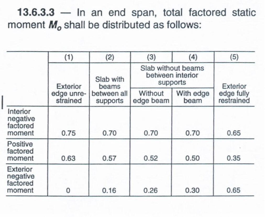
49 Positive and Negative Moments in Panels M 0 is divided into + M and -M Rules given in ACI For a typical interior panel, the total static moment is divided into positive moment 0.35 M o and negative moment of 0.65 M o. For an exterior panel, the total static moment division is dependent on the type of end conditions at the outside edge.
50 Moment Distribution
51 Distribution of M0
52 Positive and Negative Moments in Panels M 0 is divided into + M and -M Rules given in ACI sec M u M u avg M 0 w l u 8 2 l 2 n
53 Transverse Distribution of Moments The longitudinal moment values mentioned are for the entire width of the equivalent building frame. The width of two half column strips and two half-middle stripes of adjacent panels.
54 Transverse Distribution of Moments Transverse distribution of the longitudinal moments to middle and column strips is a function of the ratio of length l 2 /l 1,a f1, and b t. a f E I cb b cb 1 t E csi s 2E csi s x x y C 1 y 3 E C torsional constant
55 Distribution of M 0 ACI Sec For spans framing into a common support negative moment sections shall be designed to resist the larger of the 2 interior M u s ACI Sec Edge beams or edges of slab shall be proportioned to resist in torsion their share of exterior negative factored moments

56 Factored Moment in Column Strip

57 Factored Moment in Column Strip t Ratio of torsional stiffness of edge beam to flexural stiffness of slab(width= to beam length)
: resist a percentage of column strip moment plus moments due to loads")
58 Factored Moments Factored Moments in beams (ACI Sec ): resist a percentage of column strip moment plus moments due to loads applied directly to beams.
59 Factored Moments Factored Moments in Middle strips (ACI Sec ) The portion of the + M u and - M u not resisted by column strips shall be proportionately assigned to corresponding half middle strips. Each middle strip shall be proportioned to resist the sum of the moments assigned to its 2 half middle strips.
60 Example 13-3 and 13-4 page 650

61 ACI Provisions for Effects of Pattern Loads
62 Transfer of moments to columns Exterior columns shall be designed for 0.3M o assumed to be about the centroid of the shear perimeter, and should be divided between columns above and below the slab in proportion to their stiffnesses. Interior Columns: refer to textbook page 657
63 Shear Strength of Slabs In two-way floor systems, the slab must have adequate thickness to resist both bending moments and shear forces at critical section. There are three cases to look at for shear. 1. Two-way Slabs supported on beams 2. Two-Way Slabs without beams 3. Shear Reinforcement in two-way slabs without beams.
64 Shear Strength of Slabs 1. Two-way slabs supported on beams The critical location is found at d distance from the column, where V c f c bd / 6 The supporting beams are stiff and are capable of transmitting floor loads to the columns.
65 Shear Strength of Slabs 2. Two-Way Slabs without beams There are two types of shear that need to be addressed 1. One-way shear or beam shear at distance d from the column 2. Two-way or punch out shear which occurs along a truncated cone.
66 Shear Strength of Slabs One-way shear considers critical section a distance d from the column and the slab is considered as a wide beam spanning between supports. V ud V c f c bd / 6
67 Shear Strength of Slabs Two-way shear fails along a a truncated cone or pyramid around the column. The critical section is located d/2 from the column face, column capital, or drop panel.
68 Shear Strength of Slabs If shear reinforcement is not provided, the shear strength of concrete is the smaller of: 1. b o = perimeter of the critical section 2. 2 V c f c bod 0.33 f c bod c c =ratio of long side of column to short side asd V c f c bod bo a s is 40 for interior columns, 30 for edge columns, and 20 for corner columns.
69 Shear Strength of Slabs 3. Shear Reinforcement in two-way slabs without beams. For plates and flat slabs, which do not meet the condition for shear, one can either -Increase slab thickness - Add reinforcement Reinforcement can be done by shearheads, anchor bars, conventional stirrup cages and studded steel strips (see ACI
70 Shear Strength of Slabs Shearhead consists of steel I-beams or channel welded into four cross arms to be placed in slab above a column. Does not apply to external columns due to lateral loads and torsion.
71 Shear Strength of Slabs Anchor bars consists of steel reinforcement rods or bent bar reinforcement
72 Shear Strength of Slabs Conventional stirrup cages
73 Shear Strength of Slabs Studded steel strips
74 Reinforcement Details Loads After all percentages of the static moments in the column and middle strip are determined, the steel reinforcement can be calculated for negative and positive moments in each strip. Maximum Spacing of Reinforcement At points of max. +/- M: Min Reinforcement Requirements A A s 2 t ACI and s 45 cm ACI s min s T&S from ACI 7.12 ACI
")
75 Minimum extension for reinforcement in slabs without beams(fig )
Two-way slabs. Flat plate with or without drop panels / capitals
 Two-way slabs Two-way slab behavior is described by plate bending theory which is a complex extension of beam bending. Codes of practice allow use of simplified methods for analysis and design of two-way
DIRECT DESIGN METHOD DDM
 DIRECT DESIGN METHOD DDM Load Transfer Path For Gravity Loads All gravity loads are basically Volume Loads generated due to mass contained in a volume Mechanism and path must be found to transfer these
From Park and Gamble Book.
 From Park and Gamble Book. 1 3 4 5 Behavior of Two-Way Slabs Figure 1. Two-Way Slab on Simple Edge Supports: (a) Bending of Center Strips of Slab and (b) Grid Model of Two-Way Slab. Figure 1(a) 5wl 5wl
Agricultural Hall and Annex East Lansing, MI. Structural Design. Gravity Loads. 1- Based on US Standards
 Structural Design Gravity Loads 1- Based on US Standards Occupancy or Use Uniform (psf) Concentrated (lbs) Office building -Office -Lobbies and first-floor corridors -Corridor above first floor -Partitions
eight plates and grids Plates, Slabs & Grids Plates, Slabs & Grids Term Project plates horizontal plane, rigid slabs thin, flat, rigid
 APPLIED ARCHITECTURAL STRUCTURES: STRUCTURAL ANALYSIS AND SYSTEMS DR. ANNE NICHOLS SPRING 2018 Term Project lecture eight plates and grids Plates & Grids 1 Lecture 8 Applied Architectural Structures F2009abn
Framed, Two-Way, Conventionally Reinforced, Concrete Flat Slab and Flat Plate Construction and Design
 PDHonline Course S222 (5 PDH) Framed, Two-Way, Conventionally Reinforced, Concrete Flat Slab and Flat Plate Construction and Design Instructor: Matthew Stuart, PE, SE 2012 PDH Online PDH Center 5272 Meadow
Lecture-06 Analysis and Design of Slab Systems
 Lecture-06 Analysis and Design of Slab Systems By: Prof Dr. Qaisar Ali Civil Engineering Department UET Peshawar drqaisarali@uetpeshawar.edu.pk www.drqaisarali.com 1 Topics Addressed Organization of the
Flat Slabs. d 2. A typical flat slab (without drop and column head)
") 1 CHAPTER Flat Slabs 1.1 INTRDUCTIN Common practice of design and construction is to support the slabs by beams and support the beams by columns. This may be called as beam-slab construction. The beams
1 CHAPTER Flat Slabs 1.1 INTRDUCTIN Common practice of design and construction is to support the slabs by beams and support the beams by columns. This may be called as beam-slab construction. The beams
eight plates and grids APPLIED ACHITECTURAL STRUCTURES: DR. ANNE NICHOLS SPRING 2018 lecture STRUCTURAL ANALYSIS AND SYSTEMS ARCH 631
 APPLIED ACHITECTURAL STRUCTURES: STRUCTURAL ANALYSIS AND SYSTEMS DR. ANNE NICHOLS SPRING 2018 lecture eight plates and grids Plates & Grids 1 http://nisee.berkeley.edu/godden Term Project Plates & Grids
Software Verification
 EXAMPLE 9 ACI Handbook Two-Way Slab Example 2 PROBLEM DESCRIPTION The two-way slab system arranged three-by-three is shown in Figure 9-1. The slab consists of nine 6.5-inch-thick 20-foot 24-foot panels.
twenty two concrete construction: flat spanning systems, columns & frames ARCHITECTURAL STRUCTURES: FORM, BEHAVIOR, AND DESIGN
 ARCHITECTURAL STRUCTURES: FORM, BEHAVIOR, AND DESIGN DR. ANNE NICHOLS SUMMER 2014 lecture twenty two concrete construction: http:// nisee.berkeley.edu/godden flat spanning systems, columns & frames Concrete
twenty two concrete construction: flat spanning systems, columns & frames Reinforced Concrete Design Reinforced Concrete Design
 ARCHITECTURAL STRUCTURES: FORM, BEHAVIOR, AND DESIGN DR. ANNE NICHOLS SUMMER 2013 lecture twenty two economical & common resist lateral loads concrete construction: flat spanning systems, columns & frames
Figure: Grid or Waffle slab
 Two Way Beam Supported Slab References: 1. Design of. Reinforced Concrete, 2014, 9 th Edition, ACI 318-11 Code Edition, by Jack C. McCormac. Clemson University. Russell H. Brown. Clemson University 2.
VARIOUS TYPES OF SLABS
 VARIOUS TYPES OF SLABS 1 CHOICE OF TYPE OF SLAB FLOOR The choice of type of slab for a particular floor depends on many factors. Economy of construction is obviously an important consideration, but this
This final draft of the fib MC2010 has not been published; it is intended only for the purpose of voting by the General Assembly.
 7 Design 382 In the case of combined action of torsion, bending and shear force in a solid section, the core within the idealised hollow cross-section may be used for the transmission of the shear forces.
twenty two concrete construction: flat spanning systems, columns & frames Reinforced Concrete Design Reinforced Concrete Design
 ARCHITECTURAL STRUCTURES: FORM, BEHAVIOR, AND DESIGN DR. ANNE NICHOLS SUMMER 2014 lecture twenty two economical & common resist lateral loads concrete construction: flat spanning systems, columns & frames
Strength Design of Reinforced Concrete Structures
 Chapter 6 Strength Design of Reinforced Concrete Structures 6.1 Analysis and Design General Considerations 6.1.1 Convention and Notation Unless otherwise explicitly stated, the following units shall be
A Guide for the Interpretation of Structural Design Options for Residential Concrete Structures
 CFA Technical Note: 008-2010 A Guide for the Interpretation of Structural Design Options for Residential Concrete Structures CFA Technical This CFA Technical Note is intended to serve as a guide to assist
Chapter Three Two-way Slab Systems
 Reinforced Concrete Structures 2 (CEng-3122) Chapter Three Two-way Slab Systems 1 School of Civil and Environmental Engineering Concrete Material and Structures Chair 2 1. Introduction 2. Analysis and
Level 6 Graduate Diploma in Engineering Structural analysis
 9210-111 Level 6 Graduate Diploma in Engineering Structural analysis Sample Paper You should have the following for this examination one answer book non-programmable calculator pen, pencil, ruler, drawing
Sabah Shawkat Cabinet of Structural Engineering 2017
 3.1-1 Continuous beams Every building, whether it is large or small, must have a structural system capable of carrying all kinds of loads - vertical, horizontal, temperature, etc. In principle, the entire
PARAMETRIC STUDY ON FLAT SLAB WITH AND WITHOUT COLUMN DROP
 Vol-3 Issue- 7 IJARIIE-ISSN(O)-395-4396 PARAMETRIC STUDY ON FLAT SLAB WITH AND WITHOUT COLUMN DROP Jaydeep Chodvadiya, Vipul Vyas, Dr. G.S. Doiphode 3 PG Scholar of Structural Engineering, Charotar University,
Continuous Beam Design with Moment Redistribution (CSA A )
") Continuous Beam Design with Moment Redistribution (CSA A23.3-14) Continuous Beam Design with Moment Redistribution (CSA A23.3-14) A structural reinforced concrete continuous beam at an intermediate floor
Continuous Beam Design with Moment Redistribution (CSA A23.3-14) Continuous Beam Design with Moment Redistribution (CSA A23.3-14) A structural reinforced concrete continuous beam at an intermediate floor
REINFORCED CONCRETE STRUCTURE COURSE STR 302A CL0SED BOOK EXAM THIRD YEAR CIVIL FIRST TERM YEAR TYPES OF SLABS
 REINFORCED CONCRETE STRUCTURE COURSE STR 302A CL0SED BOOK EXAM THIRD YEAR CIVIL FIRST TERM YEAR 2012 2013 COURSE CONTENTS : DESIGN OF DIFFERENT SLABS TYPES OF SLABS - Paneled Beam Slab - Stairs - Solid
FLAT PLATE AND FLAT SLAB CONSTRUCTION
 FLAT PLATE AND FLAT SLAB CONSTRUCTION Neil M. Hawkins, Professor Emeritus, University of Illinois A Tribute to the Lasting Contributions and Legacy of Our Friend And Colleague Dr. W Gene Corley ACI Convention,
Progressive Collapse Mitigation in Flat-Slab Buildings
 Paper 245 Progressive Collapse Mitigation in Flat-Slab Buildings O.A. Mohamed Abu Dhabi University United Arab Emirates Civil-Comp Press, 2012 Proceedings of the Eleventh International Conference on Computational
SIMPLE INVESTIGATIONS OF TENSILE MEMBRANE ACTION IN COMPOSITE SLABS IN FIRE
 SIMPLE INVESTIGATIONS OF TENSILE MEMBRANE ACTION IN COMPOSITE SLABS IN FIRE By Ahmed Allam 1, Ian Burgess 1 and Roger Plank 1 Department of Civil and Structural Engineering, University of Sheffield, UK
Seismic Behaviour of RC Shear Walls
 Ductile Detailing of RC Structures :: IS:13920-1993 1993 Short Course on Seismic Design of RC Structures Durgesh C. Rai Department of Civil Engineering, IIT Kanpur The material contained in this lecture
THE EFFECT OF BEAMS STIFFNESSES ON THE LOAD DISTRIBUTION IN A SINGLE SIMPLY SUPPORTED TWO-WAY RIBBED SLAB
 The Islamic University Journal (Series of Natural Studies and Engineering) Vol.14, No.1, P.191-208, 2006, ISSN 1726-6807, http//www.iugzaza.edu.ps/ara/research/ THE EFFECT OF BEAMS STIFFNESSES ON THE LOAD
Fundamentals of Post Tensioned Concrete Design for Buildings
 Fundamentals of Post Tensioned Concrete Design for Buildings Part Three by John P. Miller Overview of This Course This is Part Two of a two-part course that covers the fundamentals of post-tensioned concrete
Analysis and Design of One-way Slab System (Part-I)
") Lecture-02 Analysis and Design of One-way Slab System (Part-I) By: Prof Dr. Qaisar Ali Civil Engineering Department UET Peshawar www.drqaisarali.com 1 Topics Addressed Concrete Floor Systems Analysis and
Lecture-02 Analysis and Design of One-way Slab System (Part-I) By: Prof Dr. Qaisar Ali Civil Engineering Department UET Peshawar www.drqaisarali.com 1 Topics Addressed Concrete Floor Systems Analysis and
THE FORENSIC MEDICAL CENTER
 THE FORENSIC MEDICAL CENTER Image courtesy of Gaudreau, Inc. TECHNICAL REPORT #2 OCTOBER 26, 2007 KEENAN YOHE STRUCTURAL OPTION DR. MEMARI FACULTY ADVISOR EXECUTIVE SUMMARY Image courtesy of Gaudreau,
DESIGN OF SLABS. 3) Based on support or boundary condition: Simply supported, Cantilever slab,
 Based on support or boundary condition: Simply supported, Cantilever slab,") DESIGN OF SLABS Dr. G. P. Chandradhara Professor of Civil Engineering S. J. College of Engineering Mysore 1. GENERAL A slab is a flat two dimensional planar structural element having thickness small compared
DESIGN OF SLABS Dr. G. P. Chandradhara Professor of Civil Engineering S. J. College of Engineering Mysore 1. GENERAL A slab is a flat two dimensional planar structural element having thickness small compared
Reinforced Concrete Continuous Beam Analysis and Design (CSA A )
") Reinforced Concrete Continuous Beam Analysis and Design (CSA A23.3-14) Reinforced Concrete Continuous Beam Analysis and Design (CSA A23.3-14) A structural reinforced concrete continuous beams at an intermediate
Reinforced Concrete Continuous Beam Analysis and Design (CSA A23.3-14) Reinforced Concrete Continuous Beam Analysis and Design (CSA A23.3-14) A structural reinforced concrete continuous beams at an intermediate
CUREe-Kajima Flat Plate 1 Kang/Wallace
 CUREe-Kajima Joint Research Program: Phase IV Assessment of the Seismic Performance of Reinforced Concrete Structures with Flat Plate Floor Systems Quarterly Report: 1/1/ 12/31/ John W. Wallace and Thomas
A Finite Element Approach to Reinforced Concrete Slab Design in GT STRUDL
 A Finite Element Approach to Reinforced Concrete Slab Design in GT STRUDL James Deaton and Dr. Kenneth M. Will 2006 GT STRUDL Users Group Meeting 23 June 2006 1 Introduction Background and Motivation The
Design of Reinforced Concrete Slabs
 Lecture 07 Design of Reinforced Concrete Slabs By: Prof Dr. Qaisar Ali Civil Engineering Department UET Peshawar drqaisarali@uetpeshawar.edu.pk 1 Topics Addressed Introduction Analysis and Design of slabs
6. Design of Portal Frames (For class held on 20 th, 26 th and 27 th March 07)
") 6. Design of Portal Frames (For class held on 0 th, 6 th and 7 th March 07) By Dr. G.S.Suresh, Professor, Civil Engineering Department, NIE, Mysore (Ph:934188467, email: gss_nie@ yahoo.com) 3.1 Introduction:
6. Design of Portal Frames (For class held on 0 th, 6 th and 7 th March 07) By Dr. G.S.Suresh, Professor, Civil Engineering Department, NIE, Mysore (Ph:934188467, email: gss_nie@ yahoo.com) 3.1 Introduction:
SIGNIFICANCE OF SHEAR WALL IN FLAT SLAB MULTI STORIED BUILDING - A REVIEW. Vavanoor, India
 SIGNIFICANCE OF SHEAR WALL IN FLAT SLAB MULTI STORIED BUILDING - A REVIEW Athira M. V 1, Sruthi K Chandran 2 1PG Student, Department of Civil Engineering, Sreepathy Institute of Management And Technology,
One-Way Wide Module Joist Concrete Floor Design
 One-Way Wide Module Joist Concrete Floor Design A 1 3 4 30'-0" 30'-0" 30'-0" 3' B 3' C 3' D 3' E 4" 4" (typ.) 3' F 0" 0" (typ.) Figure 1 One-Way Wide Module Joist Concrete Floor Framing System 1 Overview
ANALYSIS AND DESIGN OF REGULAR AND IRREGULAR FLAT SLAB FOR MULTISTOREYED BUILDING UNDER TWO SEISMIC ZONES USING ETABS AND SAFE
 ANALYSIS AND DESIGN OF REGULAR AND IRREGULAR FLAT SLAB FOR MULTISTOREYED BUILDING UNDER TWO SEISMIC ZONES USING ETABS AND SAFE THIMMAYAPALLY DILEEP KUMAR 1, A.MOWNIKA VARDHAN 2 1 M. Tech (Structural Engineering),
CADS A3D MAX. How to model shear walls
 CADS A3D MAX How to model shear walls Modelling shear walls in A3D MAX Introduction and synopsis This paper explains how to model shear walls in A3D MAX using the `wide column rigid arm sub-frame described
1. INTRODUCTION 1.1 FLAT SLAB. 275 P a g e
 Sandesh D. Bothara, Dr.Valsson Varghese / International Journal of Engineering Research and Applications Dynamic Analysis Of Special Moment Resisting Frame Building With Flat Slab And Grid Slab *Sandesh
Types of Foundations
 Shallow Foundations Types of Foundations Foundations can be classified to two major categories: Shallow. Deep. 1 Introduction If the soil stratum is suitable for supporting the structural loads from the
Pro-Con Structural Study for Alternative Floor Systems October 27, 2004
 Ismail Al-Hadhrami Structural Option Faculty Consultant: Dr. Thomas Boothby Agricultural Hall and Annex East Lansing, MI Pro-Con Structural Study for Alternative Floor Systems October 27, 2004 Executive
Masonry and Cold-Formed Steel Requirements
 PC UFC Briefing September 21-22, 2004 Masonry and Cold-Formed Steel Requirements David Stevens, ARA Masonry Requirements Composite Construction Masonry is often used in composite construction, such as
Continuous Beam Design with Moment Redistribution (ACI )
") Continuous Beam Design with Moment Redistribution (ACI 318-14) Continuous Beam Design with Moment Redistribution (ACI 318-14) A structural reinforced concrete continuous beam at an intermediate floor level
Continuous Beam Design with Moment Redistribution (ACI 318-14) Continuous Beam Design with Moment Redistribution (ACI 318-14) A structural reinforced concrete continuous beam at an intermediate floor level
INTERNATIONAL JOURNAL OF ENGINEERING SCIENCES & RESEARCH TECHNOLOGY
 [Al-Nasra, 2(2): Feb., 2013] ISSN: 2277-9655 IJESRT INTERNATIONAL JOURNAL OF ENGINEERING SCIENCES & RESEARCH TECHNOLOGY Effective Use of Space Swimmer Bars in Reinforced Concrete Flat Slabs Moayyad M.
Alternate Design Method- Design Procedure of Two-way Slabs using ACI Moment Coefficients and Approved by BNBC 2013
 Alternate Design Method- Design Procedure of Two-way Slabs using ACI Moment Coefficients and Approved by BNBC 2013 Scope and Limitations (BNBC) 6.5.8.2.1 The provisions of this section may be used as alternative
This point intends to acquaint the reader with some of the basic concepts of the earthquake engineer:
 Chapter II. REVIEW OF PREVIOUS RESEARCH II.1. Introduction: The purpose of this chapter is to review first the basic concepts for earthquake engineering. It is not intended to review the basic concepts
DESIGN FOR PROGRESSIVE COLLAPSE 1
 Your Partner in Structural Concrete Design TN447_progressive_collapse_110713 DESIGN FOR PROGRESSIVE COLLAPSE 1 Bijan O Aalami 2 This Technical Note outlines the design of column-supported conventionally
Technical Report 3. Alyssa Stangl Structural Option Advisor Dr. Linda Hanagan L A J O L L A C O M M O N S P H A S E I I O F F I C E T O W E R
 Technical Report 3 Alyssa Stangl Structural Option Advisor Dr. Linda Hanagan L A J O L L A C O M M O N S P H A S E I I O F F I C E T O W E R Site and Location La Jolla Commons, San Diego, California General
Slabs and Flat Slabs
 Slabs and Flat Slabs Lecture 5 19 th October 2017 Contents Lecture 5 Designing for shear in slabs - including punching shear Detailing Solid slabs Flat Slab Design includes flexure worked example Exercise
BS EN :2004 EN :2004 (E)
") Contents List 1. General 1.1 Scope 1.1.1 Scope of Eurocode 2 1.1.2 Scope of Part 1-1 of Eurocode 2 1.2 Normative references 1.2.1 General reference standards 1.2.2 Other reference standards 1.3 Assumptions
Contents List 1. General 1.1 Scope 1.1.1 Scope of Eurocode 2 1.1.2 Scope of Part 1-1 of Eurocode 2 1.2 Normative references 1.2.1 General reference standards 1.2.2 Other reference standards 1.3 Assumptions
DESIGN OF RC ELEMENTS UNIT 1 PART-A
 DESIGN OF RC ELEMENTS UNIT 1 PART-A 1. Calculate the design strength for M 30 grade concrete and Fe 415 grade steel? 2. What is the important principle of ultimate load method? 3. Write the classification
Section A A: Slab & Beam Elevation
 CE 331, Spring 2011 Flexure Strength of Reinforced Concrete s 1 / 5 A typical reinforced concrete floor system is shown in the sketches below. The floor is supported by the beams, which in turn are supported
mortarless masonry Design Manual Part 1 (IS 456:2000) Section 1 Page 1 IS 456:2000 PLAIN AND REINFORCED CONCRETE - CODE OF PRACTICE
 Section 1 Page 1 IS 456:2000 PLAIN AND REINFORCED CONCRETE - CODE OF PRACTICE") SECTION 1. mortarless masonry Design Manual Part 1 (IS 456:2000) Section 1 Page 1 1.1 Overview of IS 456:2000 IS 456:2000 PLAIN AND REINFORCED CONCRETE - CODE OF PRACTICE IS 456:2000 is the current Indian
SECTION 1. mortarless masonry Design Manual Part 1 (IS 456:2000) Section 1 Page 1 1.1 Overview of IS 456:2000 IS 456:2000 PLAIN AND REINFORCED CONCRETE - CODE OF PRACTICE IS 456:2000 is the current Indian
How Loads Are Distributed
 LOAD DISTRIBUTION 1 LOAD DISTRIBUTION This section illustrate how load will transmit from the deck to the stringers. Determining the fraction of load carried by a loaded member and the remainder distributed
CLT Structural Design Sylvain Gagnon, Eng. February 8, 2011 Vancouver
 www.fpinnovations.ca CLT Structural Design Sylvain Gagnon, Eng. February 8, 2011 Vancouver Structural Design Handbook 10/02/2011 2 Critical Characteristics for CLT used as floor/roof Short-term and long-term
Schöck Isokorb Type CM
 Schöck Isokorb Type Schöck Isokorb Type The Schöck Isokorb Type is suitable for cantilevered reinforced concrete slabs. (C for concrete slab) It transmits negative moment (M) and positive shear force.
ADAPT PT7 TUTORIAL FOR ONE-WAY SLAB 1
 Structural Concrete Software System TN187_PT7_tutorial_one_way_slab 012705 ADAPT PT7 TUTORIAL FOR ONE-WAY SLAB 1 1. ONE-WAY SLAB SUPPORTED ON BEAMS The objective of this tutorial is to demonstrate the
DESIGN OF VERTICAL SHEAR IN TRANSFER PLATES 1
 Structural Concrete Software System TN271_transfer_plate_shear_14 111107 DESIGN OF VERTICAL SHEAR IN TRANSFER PLATES 1 Bijan O Aalami 2 Shear normal to the plane of a transfer plate (vertical shear) is
Contents. Foreword 1 Introduction 1
 Contents Notation x Foreword xiii 1 Introduction 1 1.1 Aims of the Manual 1 1.2 Eurocode system 1 1.3 Scope of the Manual 3 1.4 Contents of the Manual 4 1.5 Notation and terminology 4 2 General principles
SEISMIC PERFORMANCE OF FLAT-SLAB SHEAR REINFORCEMENT
 SEISMIC PERFORMANCE OF FLAT-SLAB SHEAR REINFORCEMENT Ian N ROBERTSON 1, Tadashi KAWAI, James LEE 3 And Brian ENOMOTO SUMMARY The intent of this research program was to study the response of slab-column
COLUMNS 1- Definition: The Egyptian code defines columns as : 2- Types of concrete columns
 COLUMNS 1- Definition: Columns are vertical compression members which carry primarily axial compression load; the axial load may be associated with bending moments in one or two directions, as shown in
EGCE 406: Bridge Design
 EGCE 406: Bridge Design Design of Slab for Praveen Chompreda Mahidol University First Semester, 2006 Bridge Superstructure Outline Components of bridge Superstructure Types Materials Design of RC Deck
ST7008 PRESTRESSED CONCRETE
 ST7008 PRESTRESSED CONCRETE QUESTION BANK UNIT-I PRINCIPLES OF PRESTRESSING PART-A 1. Define modular ratio. 2. What is meant by creep coefficient? 3. Is the deflection control essential? Discuss. 4. Give
ANALYSIS AND DESIGN OF FLAT SLABS USING VARIOUS CODES
 ANALYS AND DESIGN O LAT SLA USING VARIOUS CODES S.S.Patil 1, Rupali Sigi 2 1 Head of Department, Civil Engineering Department, Walchand Institute of Technology, Maharashtra, India 2 Student, Civil Engineering
Supplemental Plan Check List for Concrete Special Moment Resisting Frame
 Supplemental Plan Check List for Concrete Special Moment Resisting Frame Plan Check/PCIS Application No.: Date: Your feedback is important; please visit our website to complete a Customer Survey at www.ladbs.org/ladbsweb/customer-survey.jsf.
THE FORENSIC MEDICAL CENTER
 THE FORENSIC MEDICAL CENTER Image courtesy of Gaudreau, Inc. TECHNICAL REPORT #1 OCTOBER 5, 2007 KEENAN YOHE STRUCTURAL OPTION DR. MEMARI FACULTY ADVISOR EXECUTIVE SUMMARY Image courtesy of Gaudreau, Inc.
Interaction between ductile RC perimeter frames and floor slabs containing precast units
 Interaction between ductile RC perimeter frames and floor slabs containing precast units R. C Fenwick,. J. Davidson and D.. N. Lau Department of Civil and Environmental Engineering, University of uckland.
Steel Design Guide Series. Steel and Composite Beams with. Web Openings
 Steel Design Guide Series Steel and Composite Beams with Web Openings Steel Design Guide Series Steel and Composite Beams with Web Openings Design of Steel and Composite Beams with Web Openings David Darwin
ANALYTICAL STUDY OF PUNCHING SHEAR ON WAFFLE SLAB WITH DIFFERENT RIB SIZES
 Jr. of Industrial Pollution Control 33(S2)(27) pp 323-327 www.icontrolpollution.com Research Article ANALYTICAL STUDY OF PUNCHING SHEAR ON WAFFLE SLAB WITH DIFFERENT RIB SIZES K. SAKETH*, C. ARUNKUMAR
EXPERIMENTAL INVESTIGATION ON THE INTERACTION OF REINFORCED CONCRETE FRAMES WITH PRECAST-PRESTRESSED CONCRETE FLOOR SYSTEMS
 EXPERIMENTAL INVESTIGATION ON THE INTERACTION OF REINFORCED CONCRETE FRAMES WITH PRECAST-PRESTRESSED CONCRETE FLOOR SYSTEMS B.H.H. Peng 1, R.P. Dhakal 2, R.C. Fenwick 3, A.J. Carr 4 and D.K. Bull 5 1 PhD
1 Prepared By:Mr.A.Sathiyamoorthy, M.E., AP/Civil
 UNIVERSITY QUESTIONS PART A UNIT 1: INTRODUCTION THEORY AND BEHAVIOUR 1. List the loss of prestress. 2. Define axial prestressing. 3. What is the need for the use of high strength concrete and tensile
Kaleida Health Global Heart and Vascular Institute University at Buffalo CTRC/Incubator. Buffalo, New York. Technical Report #2
 University at Buffalo CTRC/Incubator Buffalo, New York William McDevitt October 27, 2010 Table of Contents Executive Summary...3 Introduction...4 Structural System Overview...5 Foundation...5 Floor System...5
USE OF 500 GRADE STEEL IN THE DESIGN OF REINFORCED CONCRETE SLAB. Prof. M. Shafiul Bari, Ph.D Department of Civil Engg., BUET
 1.0 Introduction USE OF 500 GRADE STEEL IN THE DESIGN OF REINFORCED CONCRETE SLAB Prof. M. Shafiul Bari, Ph.D Department of Civil Engg., BUET There is growing interest within the reinforced concrete industry
13-14 May 2011 B.V.M. Engineering College, V.V.Nagar,Gujarat,India
 COST COMPARISON BETWEEN FLAT SLABS WITH DROP AND WITHOUT DROP IN FOUR STOREY LATERAL LOAD RESISTING BUILDING Vikunj k.tilva M.E Student, Applied Mechanics Department, L. D. College of Engineering, Ahmadabad,
Modelling of RC moment resisting frames with precast-prestressed flooring system
 Modelling of RC moment resisting frames with precast-prestressed flooring system B.H.H. Peng, R.P. Dhakal, R.C. Fenwick & A.J. Carr Department of Civil Engineering, University of Canterbury, Christchurch.
Seismic Performance Of R C Flat-Slab Building Structural Systems
 Research Paper Volume 2 Issue 9 May 2015 International Journal of Informative & Futuristic Research ISSN (Online): 2347-1697 Seismic Performance Of R C Flat-Slab Building Paper ID IJIFR/ V2/ E9/ 027 Page
APPENDIX B ABC STRUCTURES DESIGN GUIDE
 APPENDIX B ABC STRUCTURES DESIGN GUIDE The Cohos Evamy Partners TABLE OF CONTENTS Page No. DISCLAIMER... I 1. STRUCTURAL DESIGN GUIDELINES... 1 2. GENERAL REQUIREMENTS (FIGURE B.2, STEP 1)... 1 3. GENERAL
Design of Post Tensioned Slab (Review)
") Design of Post Tensioned Slab (Review) Arun S. Bhutekar, Kishor S. Mirge, Bhavna Mhaske, Mangesh J. Sarkate, Prof,N. N. Shinde Department Civil Engineering, Email: bhutekararun143@gmail.com ABSTRACT- The
Design of Post Tensioned Slab (Review) Arun S. Bhutekar, Kishor S. Mirge, Bhavna Mhaske, Mangesh J. Sarkate, Prof,N. N. Shinde Department Civil Engineering, Email: bhutekararun143@gmail.com ABSTRACT- The
Case Study in Steel adapted from Structural Design Guide, Hoffman, Gouwens, Gustafson & Rice., 2 nd ed.
 Case Study in Steel adapted from Structural Design Guide, Hoffman, Gouwens, Gustafson & Rice., 2 nd ed. Building description The building is a one-story steel structure, typical of an office building.
Structural Option April 7 th, 2010
 Gravity System (Depth Topic I) Post Tensioned Slab A new floor system was designed in an attempt to create a more consistent flooring system throughout the entire building. This new design consists of
Presentation Overview
 Presentation Overview Structural System Overview Dr. J. Bracci Spring 2008 Semester 1. Building system primary functions 2. Types of load 3. RC structural systems 4. RC structural members 2 1. Basic Building
PERFORMANCE STUDY OF RETROFITTED GRAVITY LOAD DESIGNED WALL FRAME STRUCTURES (SC-140)
") PERFORMANCE STUDY OF RETROFITTED GRAVITY LOAD DESIGNED WALL FRAME STRUCTURES (SC-140) *A. Ahmed 1, K. H. Tan 1 1 Department of Civil and Environmental Engineering National University of Singapore, Singapore,
PERFORMANCE STUDY OF RETROFITTED GRAVITY LOAD DESIGNED WALL FRAME STRUCTURES (SC-140) *A. Ahmed 1, K. H. Tan 1 1 Department of Civil and Environmental Engineering National University of Singapore, Singapore,
A STUDY COMPARISON OF DROP PANELS UNDER INFLUENCE OF PUNCHING SHEAR USING ANSYS.16.0
 A STUDY COMPARISON OF DROP PANELS UNDER INFLUENCE OF PUNCHING SHEAR USING ANSYS.16.0 Yogesh A.Chaudhari 1, Prof.G.B.Katti 2 1 PG Student, 2 Professor, Department of Civil Engineering, Late G. N. Sapkal
Reinforced Concrete Spread Footing (Isolated Footing) Analysis and Design. Design Footing
 Analysis and Design. Design Footing") Reinforced Concrete Spread Footing (Isolated Footing) Analysis and Design Design Footing Reinforced Concrete Spread Footing (Isolated Footing) Analysis and Design A square spread footing supports an 18
Reinforced Concrete Spread Footing (Isolated Footing) Analysis and Design Design Footing Reinforced Concrete Spread Footing (Isolated Footing) Analysis and Design A square spread footing supports an 18
MULTI-STOREY BUILDINGS - II
 38 MULTI-STOREY BUILDINGS - II 1.0 INTRODUCTION Modern design offices are generally equipped with a wide variety of structural analysis software programs, invariably based on the stiffness matrix method.
Fz LLC. Exclusive Distributor in the Middle East for CSI Software licensing, technical support and training solutions
 Exclusive Distributor in the Middle East for CSI Software licensing, technical support and training solutions www.techiesoft.com For Sales: sales@techiesoft.com For Technical Support: support@techiesoft.com
Hilton Baltimore Convention Center Hotel Western Podium
 Hilton Baltimore Convention Center Hotel Western Podium CHRIS SIMMONS Structural Option Faculty Consultant: Dr. Ali M. Memari Technical Report 2 TABLE OF CONTENTS EXECUTIVE SUMMARY. Page 3 INTRODUCTION..
Tests of R/C Beam-Column Joint with Variant Boundary Conditions and Irregular Details on Anchorage of Beam Bars
 October 1-17, 8, Beijing, China Tests of R/C Beam-Column Joint with Variant Boundary Conditions and Irregular Details on Anchorage of Beam Bars F. Kusuhara 1 and H. Shiohara 1 Assistant Professor, Dept.
Council on Tall Buildings
 Structure Design of Sino Steel (Tianjin) International Plaza Xueyi Fu, Group Chief Engineer, China Construction Design International 1 1 Brief of Project 2 Location: Tianjin Xiangluowan Business District
> 0. 1 f, they are treated as beam-columns.
 223 A- Flexural Members (Beams) of Special Moment Frames Requirements of ACI 21.5 are applicable for special moment frame members proportioned primarily to resist flexure with factored axial forces 0.
fifteen design for lateral loads Lateral Load Resistance Load Direction Lateral Load Resistance
 APPLIED ARCHITECTURAL STRUCTURES: STRUCTURAL ANALYSIS AND SYSTEMS DR. ANNE NICHOLS FALL 2013 lecture fifteen design for lateral loads Lateral Load Resistance stability important for any height basic mechanisms
Shear studs in slab-column connections with rectangular column
 Shear studs in slab-column connections with rectangular column C B Tan*, Nanyang Techological University, Singapore s C Lee, Nanyang Techological University, Singapore s Teng, Nanyang Techological University,
ADAPT-PT 2010 GETTING STARTED GUIDE
 ADAPT-PT 2010 GETTING STARTED GUIDE Copyright ADAPT 2007, 2008 all rights reserved support@adaptsoft.com www.adaptsoft.com ADAPT Corporation, Redwood City, California, USA, Tel: +1 (650) 306-2400 ADAPT
Chapter 2 Notation and Terminology
 Reorganized 318 Chapter Titles Chapter 1 General 1.1 Scope 1.2 Purpose 1.3 Interpretation 1.4 Drawings and Specifications 1.5 Testing and Inspection 1.6 Administatration and Enforcement 1.6.1 Retention