IntegraLine FRP SOLUTIONS MADE SIMPLER
|
|
|
- Dominic Malone
- 6 years ago
- Views:
Transcription


1 Integraine Standard orem Ipsum FRP Pipe Dolor For Sit Chemical Amet Coret Processing Detum Plants FRP SOUTIONS MADE SIMPER
2 Introduction Introducing Integraine* Pipe After years of serving corrosion-related industries, Fibrex noticed there seemed to be no easy approach to selecting and designing fiberglass reinforced plastic (FRP) pipe. Most plants have worked with fabricators and engineers to custom design all FRP equipment. Yet there is considerable cost and effort to custom design pipe or a pipe system and it is not always necessary. Fibrex has found there are many applications where a standard FRP pipe product will meet all of the requirements. That's why Fibrex has developed a standard pipe product line called Integraine. Integraine is a standard production pipe with custom corrosion resistance. Simple to specify and select, this pipe is ideal for new system installation or replacement of existing pipe. Integraine pipe will meet many of the applications and life-span requirements at your plant or facility. For special design requirements, Fibrex also offers custom-pipe solutions. Custom-pipe solutions may require thicker corrosion or abrasion barriers with different resins. Also, heavier structural laminates and special glass reinforcements are available to meet installation and temperature requirements. Fibrex can provide design recommendations for a proposed installation. And because Fibrex understands the industries we serve, Fibrex products are designed to meet the most demanding and specialized conditions at each site. In standard pipe, custom pipe, special header systems, duct or stacks, Fibrex delivers long-term corrosion solutions and absolute maximum product life. We call this "performance-based manufacturing." cost savings faster production and quicker delivery fast and easy pipe selection *Trademark of Fibrex Corporation
3
4 Contents Integraine Product Information & Construction Details...2 Integraine aminate Construction (illustration)...3 Pipe Design and Selection Pressure Classes - Pipe...4 Pressure Classes - Fittings...5 Elbows...6 A ID 90 B ID 45 Reducers...7 Full Face and Blind Flanges...8 Stub Ends with Steel Backing Flanges...9 T Flanged Joints - Fastener Requirements...10 BC Flanged Joints - Bolting Torque and Sequence...11 OD ID Fabricated Branch Connections...12 Flow Chart...13 System Design Supports...14 Expansion and Contraction...14 Water Hammer...15 Vibration...15 Hydrostatic Testing...15 Allowable Spans Between Supports...16 System Direction Changes (Offset egs)...18 inear Thermal Expansion...19 Hanger ine 3 Guide D C Minimum ength of Offset eg...19 Riser Clamp ine 2 Expansion oops...20 Maximum Guide Spacing...20 Compressive End oads Due to Thermal Expansion...21 B Anchor A ine 1 Guide Support Saddle Supports...22 Hanger Supports...23 Field Installation Joining Procedures...24 Field Joint Material Requirements...27 Shipping, Handling and Storage...28 mat inside overlay exterior overlay woven roving 1
5 Product Information Corrosion Resistance Integraine fiberglass reinforced plastic (FRP) pipe is designed to be user friendly. The resin, glass reinforcement materials and composite construction were selected to provide consistent corrosion resistance for the majority of chemical applications for which FRP pipe is considered appropriate. There remain certain extreme chemical services for which special construction and alternative resins should be considered. Fibrex can advise if this is required for your application. Weather Resistance Integraine pipe utilizes a heavily resinated exterior coat containing an ultraviolet stabilizer to impart long term resistance to the effects of sunlight and other weathering elements. Should pipe become weathered after many years in particularly severe environments, the exterior can be sanded and resin coated or painted. Color Pigmented exterior gel coats are not used on Integraine pipe in order to take advantage of the natural translucency of FRP. Visual inspection of the pipe, both new and after years of service, is more reliable with a natural laminate. Additionally, the liquid contents can often be observed in the pipeline sometimes a process control advantage. When special color coding is required, however, this can be provided at a nominal added cost and slightly longer delivery time. Durability The high tensile elongation properties of the vinyl ester resins utilized in Integraine pipe impart a superior toughness to the pipe enabling it to resist cracking and crazing of the resin when subjected to heavy design loads. In addition to high fatigue resistance, this toughness also provides a safety factor against impact damage during shipping and installation. Construction Details Resin Integraine pipe is manufactured with a premium vinyl ester resin as the standard production resin. Other vinyl ester resins specified by the customer are available, however delivery lead times will generally be longer. Epoxy vinyl ester resins are premium corrosion resistant resins. At both room and elevated temperatures, these resins offer resistance to a broad range of acids, alkalis, bleaches and solvents making them the appropriate choice of resins in many chemical processing industry applications. These resins, when properly formulated and cured, comply with FDA regulation 21 CFR covering materials intended for repeated use in contact with food. Specific chemical resistance information can be found in the Chemical Resistance and Engineering Guides, available from FIBREX or directly from the resin manufacturers. Reinforcement Materials A C glass (chemical grade) veil is provided on all surfaces exposed to corrosive media. Fiberglass used in all subsequent layers of the laminate has excellent electrical resistivity, high tensile strength, moderate thermal conductivity and is noncombustible. The basic types of fiberglass materials used; mat, woven roving and continuous strand, are selected for their physical properties, manufacturing characteristics and the chemical resistance of the laminate resulting from their use. Corrosion Barrier The corrosion barrier of Integraine pipe is nominally 100 mils thick and is comprised of 70% to 80% resin. This highly resinated laminate is reinforced by one layer of C glass veil followed by two layers of randomly oriented fiber strand mat. Structural aminate Straight Pipe Integraine pipe is manufactured by the filament winding process utilizing continuous fiberglass strand wound in a helical pattern at a nominal 55 degree wind angle to produce an optimum combination of hoop and axial properties for most typical applications. The high glass content resulting from the filament winding process imparts excellent strength characteristics to the laminate providing superior protective structural backup to the resin rich corrosion barrier. Fittings Integraine pipe fittings are manufactured utilizing a highly efficient contact-molded laminate consisting of alternating layers of glass fiber strand mat and bi-directional woven glass roving. The high glass content resulting from the specific laminating process used for Integraine pipe fittings permits the wall thickness of this hand-layup process to closely approximate the wall thickness of filament wound straight pipe in equivalent pressure rated classes. 2
6 Integraline aminate Construction Filament Wound aminate Corrosion Barrier (Abrasion Barrier) (Thickness.100" nominal) Structural Wall (Thickness in accordance with pressure rating) Note: Corrosion/Abrasion Barrier may be thicker for specific applications. Contact Molded aminate C-Glass surface veil Chopped Strand Mat Woven Roving Filament Wound Strand Outer surface layer with U.V. inhibitor Structural Wall (Thickness in accordance with pressure rating) Corrosion Barrier (Abrasion Barrier) (Thickness.100" nominal)
7 Pipe Design & Selection Pressure Classes: Filament Wound Pipe 50 PSI D T W V S Total Wall Unit Allowable Max. Type I Diameter Thickness Weight Vacuum Simple Span* (in.) (in.) (lb.) (psi) (ft.) PSI D T W V S Total Wall Unit Allowable Max. Type I Diameter Thickness Weight Vacuum Simple Span* (in.) (in.) (lb.) (psi) (ft.) PSI D T W V S Total Wall Unit Allowable Max. Type I Diameter Thickness Weight Vacuum Simple Span* (in.) (in.) (lb.) (psi) (ft.) *Based on fluid contents specific gravity of 1.2
8 50 PSI D T W T Diameter Total Wall Unit Flange 90 Ell Full Face Stub End Reducer Pipe Pipe Full Face U N I T W E I G H T S Thickness Weight Thickness Flange Flange (1 size red.) / / / / / / / / / / / / / Pipe Design & Selection Pressure Classes: Contact Molded Pipe & Fittings 100 PSI D T Pipe W Pipe Full T Face U N I T W E WI G H T S Diameter Total Wall Unit Flange 90 Ell Full Face Stub End Reducer Thickness Weight Thickness Flange Flange (1 size red.) / / / / / / / / / / / / / PSI D T Pipe W Pipe Full T Face U N I T W E I G H T S Diameter Total Wall Unit Flange 90 Ell Full Face Stub End Reducer Thickness Weight Thickness Flange Flange (1 size red.) / / / / / / / / / / / / / Pipe total wall thickness is based on high-strength laminate (HS) using 3/4 oz mat / 24 oz woven roving in structural layers. 5
9 Pipe Design & Selection ong Radius 90 /45 Elbows A ID 90ϒ NOTE: 1. Dimension A (90 ), or B (45 ) can be reduced with mitered construction. B ID Optional Flanged Elbows A 45ϒ 90 Elbow D A ID Diameter A Elbow D ID B Diameter B 2 1-5/ / / / / / / / / / /8 A NOTES: 1. = Standard Stub length unless specific length is requested. 2. Elbow with either full face flanges or flanges with steel backing rings. 3. Elbows can be provided with flange laminated to the pre-manufactured elbow, however these should be used only as a necessary alternative to the preferred configuration shown. 6
10 Pipe Design & Selection Reducers D D S D See Note 2 DS Notes: 1. Formula for length of reducer =2-1/2 (D - D S ) 2. Formula for eccentric offset E= D - D S 2 3. For length of standard flange see appropriate flange table. 4. engths other than those shown are available. Reducers with full face flanges The large end of the reducer can be provided in flanged configuration. Reducers are available with either full face flanges or stub flanges with steel backing rings. 7
11 Pipe Design & Selection Full Face and Blind Flanges T See Contact Molded Pressure Class Tables OD BC ID T BC OD D ID D OD* H Number Diameter H B BC Flange T Thickness Diameter Outside of Holes of Holes Bolt 50 PSI 100 PSI 150 PSI Stub ength Diameter circle 1-1/ /8 3-7/8 1/2 9/16 11/ /4 4-3/4 1/2 9/16 11/ / /4 5-1/2 1/2 11/16 3/ /2 4 3/4 6 1/2 11/16 13/ /4 7-1/2 9/16 13/16 15/ /8 9-1/2 5/8 7/8 1-1/ /2 8 7/8 11-3/4 3/ / /4 7/8 1-3/16 1-7/ /16 1-3/ /8 18-3/4 1-1/16 1-1/2 1-7/ / /8 21-1/4 1-3/16 1-5/8 2-1/ /4 22-3/4 1-1/4 1-3/4 2-1/ / / /16 1-7/8 2-7/ /8 29-1/2 1-1/2 2-1/8 2-13/ / / /8 2-1/2 3-3/ /8 42-3/4 2-3/ / *Tolerance on O.D. is - 0" + 1 / 2 " Flange drilling per ANSI B16.1, Class 125 (identical to ANSI B16.5, Class 150 through 24" dia.) 8
12 Pipe Design & Selection T See Contact Molded Pressure Class tables Tapered Flat Stub Ends with Steel Backing Flanges OD ID All pressures up through 6" and all 50 PSI PSI 8" and larger Stub End D D T ID OD Flange Thickness Diameter Outside Stub ength Diameter 50 PSI 100 PSI 150 PSI 2 4 1/2 1/2 1/ /4 1/2 1/2 9/ /4 1/2 9/16 5/ /8 1/2 9/16 3/ /8 1/2 11/16 7/ /4 9/16 13/ /16 15/16 1-5/ /8 5/8 1-1/16 1-3/ /8 5/8 1-1/16 1-1/ /2 3/4 1-1/8 1-5/ /4 3/4 1-1/4 1-5/ /8 7/8 1-1/2 1-3/ /8 15/ /16 2-5/ /8 1-1/ /8 15 T 1/4" Chamfer ID BC OD Steel Backing Flange D D D D N N T W ID OD BC Pipe Inside Diameter Outside Bolt Circle Number Diameter Thickness Approx. Diameter 50psi 100psi 150psi Diameter Diameter of Holes of Holes Weight* 2 2-5/8 ID's are for 6 4-3/4 4 3/4 5/ /4 SK-39-S0 7-1/ /4 5/ /4 or 9 7-1/2 8 3/4 5/ /2 8 7/8 3/4 9.5 SK-70-S /2 11-3/4 8 7/8 3/ / / /8 19 SK-70-PSO / / / / /2 21-1/ / SPECIA / /4 1-1/ BORE 27-1/ /4 1-1/ / /8 1-1/ /4 38-3/ /8 1-1/ / / /8 1-1/4 175 *Weight varies with inside Diameter 9
13 Pipe Design & Selection Flanged Joints - Fastener Requirements Full Face Gasket Flat Washer FU FACE FANGE CONNECTION FRP or Metal Spacer Ring Raised Face Metal Flange Steel Backing Flange Ring Gasket STUB FANGE WITH STEE BACKING FANGE CONNECTION Full Face Gasket Full Face Flange Flat Washer Flat Washer Full Face FRP Flange META RAISED FACE FANGE TO FU FACE FRP FANGE CONNECTION Stub Flange FRP or Metal Spacer Ring Full Face Gasket Steel Backing Flange Flat Washer Flat Washer Full Face Flange Stub Flange FU FACE FANGE TO STUB FANGE WITH STEE BACKING RING CONNECTION D P T Q D Flange Rated Flange Quantity Diameter Bolt Diameter Pressure Thickness Required ength /2 4 5/8 2-1/ /16 4 5/8 2-1/ /16 4 5/8 2-3/ /2 4 5/8 2-1/ /16 4 5/8 2-3/ /16 4 5/ /16 8 5/8 2-1/ /16 8 5/ /16 8 5/8 3-1/ /8 8 3/4 2-3/ /8 8 3/4 3-1/ /16 8 3/4 3-1/ /4 8 3/ /4 3-1/ /4 8 3/ /8 12 7/8 3-1/ / / / /8 4-1/ /8 3-1/ / /8 4-1/ /4 12 7/ / / / / / / / / / / /8 4-1/ / /8 5-1/ / /8 6-1/ / /8 4-3/ / /8 5-3/ / / / /4 5-1/ / /4 6-1/ / / / / / /4 7-1/ / / / / / /2 8-1/ /2 10-1/2 NOTES: 1. Use full face or ring gasket as indicated in sketches. 2. Do not connect full face flanges to raised face or stub flanges without a spacer ring. NOTES: 1. Bolt lengths are calculated for full face FRP flanges. ength requirements for stub ends with steel backing flanges may vary and should be verified with FIBREX. 2. Bolt lengths are adequate for (2) washers plus heavy hex nut and 1/8" thick gasket with excess of 3/8"-1/2". 3. Use ANSI Type A Narrow or Type B Narrow plain washers. 4. Use gaskets with Shore A durometer of Gaskets should be 1/8" minimum thickness up through 24" diameter and 3/16" for 30 and 36" diameter. 10
14 Pipe Design & Selection Flanged Joints - Bolting Torque and Sequence Gaskets should have a Shore A durometer of with the following minimum thickness; 1/8" thru 20" diameter, 3/16" - 24" - 36" diameter. 2. Bolts should initially be tightened to 50% of the values shown. Subsequent tightening should be in the same sequence until the required torque is reached. Typical Bolt Torque Force Required for Sealing D Pipe 50 PSI 100 PSI 150 PSI Diameter in. ft. - lb of torque NOTE: The indicated torque is suggested to seal flanges in pressure pipe using gaskets of a Shore A durometer of 50 to 60. Maximum Bolt Torque for Pressure Piping D T Bolt Size in. Torque ft. - lb. 1/2 15 5/8 25 3/4 40 7/ / / / / Based on a 12,000 psi bolt stress. Use ANSI Type A Narrow or Type B Narrow plain washers. 11
15 Pipe Design & Selection Fabricated Branch Connections ID Diameter A B C D A A A ID C ID B D 45 NOTES: 1. A is the minimum recommended length to allow for a joint overlay. 2. Tees, including reducing tees, are not one-piece construction but are manufactured by joining one section of pipe into the sidewall of another. For this reason it is rarely of benefit to order a tee fitting as an individual component. The main run of pipe can be provided with the required branch line stub thereby saving shop and field joints. Pipe Coupling Connection NPT A 10 gauge 1/4 3" 3/8 3" 1/2 3-1/2" 3/4 3-1/2" 1 4" 1-1/4 4" 1-1/2 4-1/2" A Std NPT threads Overlay Side View Thixotropic resin filler End View 12
16 Pipe Design & Selection Flow Chart Head oss vs. Flow Rate Head oss - Feet of Water per 100 feet of Pipe inch inch 10 inch 12 inch F l o w v e l o c i t y f t. p e r s e c o n d 14 inch 16 inch 18 inch 20 inch 24 inch 30 inch 36 inch , ,000 Flow Quantity - Gallons per Minute Friction osses of Fittings in Equivalent ength of Straight Pipe Fitting - Diameter Smooth Turn Ell Smooth Turn Ell Tee - Through Flow Tee - Branch Flow
17 System Design Integraine pipe has excellent corrosion resistance and mechanical properties. However, as with any piping material, good application design and installation practices will greatly enhance the reliability and service life of the pipe system. The following suggestions describe a rudimentary approach to laying out the piping system. This approach does not include all possible contingencies and is not intended to replace more extensive design approaches, such as finite element analysis, when the designer judges these to be appropriate. Supports 1. Select preliminary support locations. Steel supports for Integraine pipe should be spaced at maximum intervals shown in the tables on page 17. These distances should not be exceeded. A reduction of 10% in the distance between supports should be considered when: (a) pipe is carrying fluids with specific gravities in the range of 1.1 to 1.3 (b) fluid contents of the pipe may be over 180 degrees Fahrenheit (c) wind loads, vibration or other factors present may increase loads on the pipe run 2. Use support saddles of adequate size to eliminate the possibility of point loading. A good rule of thumb is that saddles should provide complete 180 degree support of the lower half of the pipe. Saddle length should be equal to the diameter of the pipe for small sizes and not less than two thirds the diameter of the pipe for larger sizes. 3. Valves, pumps, and other heavy equipment connected to the pipe should be supported independently to avoid imposing excessive loads on the pipe. 4. Vertical pipe runs should be supported from below so that pipe is in compression. 5. A minimum 1/8" thick layer of neoprene or other elastomeric material should be provided between the pipe and the steel support saddle to insure maximum contact and to prevent abrasion. Thicker layers may be used to fill any excess space between the outside wall of the pipe and the interior curvature of the saddle. 6. When long runs of pipe are hung from overhead structures, guides should be incorporated periodically (every third or fourth hanger location) to provide lateral stability. Expansion & Contraction Integraine pipe expands in the axial direction at approximately twice the rate of steel. However, because it has a relatively low axial modulus of elasticity, thermal forces are smaller and therefore restraining anchors and guides need not be as heavy as for steel pipe. Common practice for above-ground piping systems is to provide anchors at approximately 300 ft. intervals. This helps to prevent pipe movement due to vibration or water hammer. In addition to the natural anchor points in the system, such as equipment connections, it is a good idea to provide anchors at transition points where changes in pipe diameter, direction or elevation, material of construction or major branch connections occur. This serves to divide the piping system into individual expanding sections that are simpler to deal with. Expansion and contraction are usually handled by one or a combination of the following methods: 1. Directional Changes in the System. When sufficient flexibility exists within the piping system layout, using directional changes is generally the least expensive means to accommodate expansion and contraction. A typical approach to this method is described on page Mechanical Expansion Joints. Various types of expansion joints are used successfully with FRP pipe. The following points should be considered when selecting an expansion joint: (a) Because thermal forces developed are much lower than for steel pipe, it is essential to use an expansion joint which is activated by low forces. The force required to compress the expansion joint must not be greater than the force shown in the Compressive End oads table on page 21. (b) In installations where the pipe may operate at a lower temperature than the installation temperature, it may be necessary to pre-set the expansion joint for contraction. 14
18 System Design (c) Guides should be installed to assure that the pipe will remain aligned through the expansion joint. ocate guides not more than 4 times the diameter of the pipe on either side of the expansion joint. 3. Expansion loops. This approach consists of an arc of pipe that flexes to accommodate changes in length. The design method is based on stress developed in a cantilevered beam with a concentrated load at the free end. It ignores flexibility of the loop leg parallel to the pipe line. Guidance for sizing of expansion loops is given on page Anchor supports and guides. For very short pipe runs and/or small changes in temperature, it is frequently unnecessary to make provisions for thermal expansion. The system designer should be aware however, that when pipe is restrained by anchor supports in lieu of providing other means to accommodate expansion, both pipe and anchor supports will be subjected to the end loads shown in the Compressive End oads table on page 21. Supporting structural steel and steel anchor supports must therefore be capable of resisting these forces. When longer runs of pipe are restrained in this manner, it is necessary to provide guides to keep the pipe line straight, thereby directing forces in an axial direction to prevent buckling which might otherwise occur. Maximum guide spacing is given in the table on page 20. FRP thrust collars are laminated to the pipe on either side of an anchor support to restrain the pipe and are also used with riser clamps for vertical support. Collars are generally applied while the pipe is being manufactured but can also be applied in the field. Water Hammer The high pressure surge or shock load known as water hammer is produced by abrupt changes in fluid velocity within the pipe. The usual causes are instantaneous valve closing or opening, as well as pump start-up or shutdown. Pressure gauges, due to slow response time, frequently do not register water hammer pressure surges however violent vibration or movement in the pipeline can sometimes be observed. Complete explanations and calculations for this phenomenon can be found in piping handbooks. Under certain conditions these shock forces can be of sufficient magnitude to rupture a piping system. The system designer is cautioned to take measures to prevent or reduce these forces. One method would be to use slow-closing valves or surge tanks. Additionally, pumps should never be started into empty discharge lines unless valves are used to control flow. A check valve should be installed to control the velocity of liquid flowing back through a line. As a general guideline, Integraine pipe will withstand a dynamic pressure increase equal to the pressure rating of the pipe, however the system must be adequately anchored and supported, particularly at changes in direction and branch connections, to prevent movement of the pipeline. Vibration Although low-amplitude vibration from a well-anchored centrifugal pump will generally have little effect on Integraine pipe, adjacent supports should be well cushioned to prevent abrasion of the exterior of the pipe. arge amplitude vibration should be isolated from the pipe through the use of flexible connectors. Hydrostatic Testing Whenever possible, FRP piping systems should be hydrostatically tested prior to process start-up. Testing with air or gas is extremely hazardous and is not recommended. The following approach to testing the system is suggested: 1. Insure that all supports, guides and anchors are in place and the line is properly restrained. 2. Introduce water to the system at the lowest point, preferably through a 1" diameter or smaller pipe. 3. Provide a means to bleed air off, such as loosening a flange or partially opening a valve, at the highest point in the system. 4. When the system is filled, slowly close the air bleed-off point and gradually bring the system up to the desired pressure. 5. Test pressure should not exceed 1-1/2 times the system operating pressure or 1-1/2 times the rated operating pressure of the pipe. 15
19 System Design Allowable Spans Between Supports 50 PSI D T Diameter Wall Type I Type II Type III Type IV Thickness PSI D T Diameter Wall Type I Type II Type III Type IV Thickness PSI D T Diameter Wall Type I Type II Type III Type IV Thickness NOTE: All spans based on fluid contents specific gravity of 1.2
20 System Design Type I Simply supported spans (two supports per span length) with the run attached to a fitting at one end, or any other section of less than three span lengths. Allowable Spans Between Supports Type II Continuous beam of three spans, all loaded. Type III Continuous beam of four or more spans, all loaded. Type IV Beam fixed at both ends, uniformly distributed loads. 17
21 System Design System Direction Changes D Hanger ine 3 Guide C Riser Clamp ine 2 Anchor B A ine 1 Guide Support Using System Direction Changes (Offset egs) to Deal with Expansion The illustration above depicts a typical installation configuration. To use this particular configuration to advantage in allowing for pipe expansion, the following steps would be appropriate: 1. Using the inear Thermal Expansion table (Page 19), determine the maximum expansion of line 1 from any prior anchor point. This value is used with the Minimum ength Of Offset eg table (page 19) to find the minimum length of the offset leg B. 2. Determine the maximum expansion of that portion of line 2 between the anchor support and the lower elbow. This value is then used to find the minimum length of the offset leg A. 3. Determine the maximum expansion of line 3 from any prior anchor point and use this value to find the minimum length of the offset leg C. (Note: If the upper support location on the vertical run did not allow for an adequate distance to the upper elbow, it can be allowed to slide and the distance from the upper elbow to the anchor support then becomes the offset leg.) 4. Determine the maximum expansion from the anchor support to the upper elbow and use this value to find the minimum length of the offset leg D. NOTES: 1. Generally, the support which satisfies the minimum offset leg length should prevent lateral movement and buckling. A Guide Support is frequently used for this purpose. 2. After determining the minimum allowable distance of the offset leg, check the Allowable Span table (page 16) to determine if additional supports between the elbow and the offset leg guide support are required. These should be sliding supports, allowing for both axial and lateral movement. 3. Steel supports, which satisfy the more commonly encountered requirements, are available from FIBREX and are shown in this manual. 18
22 System Design System Direction Changes inear Thermal Expansion Change in Temperature - Degrees F Change in ength - inches per 100 ft. Minimum ength of Offset eg Deflection of Offset eg - (inear expansion of main run) - inches Diameter ength of Offset eg - feet inear Expansion of main run Sliding Support Fixed Support 19
23 System Design Expansion oops B A Total Change in ength Anchor Additional Supports as Required First Guide ength First Guide ength Anchor Second Guide ength Second Guide ength Where straight runs with anchors at both ends are required, system direction changes (offset legs) can be replaced by an expansion loop to accommodate changes in length due to expansion. This is similar to creating back-to-back offset legs. The following steps are used to determine appropriate dimensions for an expansion loop: 1. Determine an available location for the expansion loop. It is not mandatory that the loop is equidistant between the two anchors however to the extent this is possible, the size of the loop will be minimized. 2. Determine the maximum change in temperature between the installation temperature and highest (or lowest) operating temperature. 3. Determine the distance between the expansion loop location and the farther of the two anchor supports. 4. Refer to the Minimum ength Of Offset eg table (page 19) to determine the minimum length of leg A. 5. eg length B should not be less than one half the length of A. 6. The distance to the first guide on either side of the loop should be no more than 4 times the diameter of the pipe and distance to the second guide, no more than 16 times the pipe diameter. 7. A support under leg B may be provided, however, do not provide any guides within the loop which could constrain pipe movement in the direction of the pipe run. Maximum Guide Spacing in Feet Change in Temperature - degrees F Diameter distance between guides 20
24 System Design 50 PSI 100 PSI Compressive End oads due to Thermal Expansion Temperature Change - degrees F Diameter Restraining pipe expansion with anchors in these temperature ranges will result in excessive axial pipe stresses Temperature Change - degrees F Diameter Restraining pipe expansion with anchors in these temperature ranges will result in excessive axial pipe stresses 150 PSI Temperature Change - degrees F Diameter Restraining pipe expansion with anchors in these temperature ranges will result in excessive axial pipe stresses 21
25 System Design Saddle Supports Cradle Support D Pipe Size Standard steel strapping for Cradle Support not included. Saddle Support D Pipe Size Order Guide Bands separately when required. T W Anchor Support D Pipe Size T W / / / / /
26 System Design Clevis Hanger D Pipe Size Hanger Supports Clamp Hanger D Pipe Size T Riser Clamp T D Pipe Size E T W / / / / / W E W F E Integraine steel supports are available from Fibrex or can be provided by customer. 23
27 Field Installation Joining Procedures inside overlay exterior overlay woven roving mat Joining Procedures Integraine pipe makes use of the joint type widely recognized as being the most corrosion resistant and reliable of all currently available means of connecting FRP pipe components the BUTT JOINT, sometimes also known as the butt wrap joint or the butt and strap joint. This type of joint is analogous to a weld in metallic piping systems and consists essentially of a strap of laminate wrapped around the exterior of the two parts being joined. This joint uses the same materials of construction as the pipe fittings. The result is a homogeneous weld, without the potential for problems sometimes associated with systems utilizing various adhesives, mechanical components or other materials of dissimilar composition. Since Integraine pipe is not about compromises, FIBREX strongly recommends the use of the BUTT JOINT rather than seemingly more convenient, but potentially less reliable, alternative types of joints. It may take days to become proficient at welding stainless steel, but it takes only a few hours to become an expert at welding FRP pipe. Before You Start... you will need: 1. for weighing and measuring - graduated cylinder ( metric ) - weighing scale (25lb to 60 lb capacity) - floor paper, flexible plastic strip or other material to wrap around pipe 2. for cutting and surface preparation - power sander and sanding discs (24 grit & 60 grit ) - barrel grinder - circular saw (diamond coated or carbide grit masonry blade) - saber saw or hack saw (carbide tip or grit blade) if irregular cuts will be required 3. for applying laminate materials - stiff bristle brushes - 3" wide laminating roller (bristle or metal fin) - 6" wide paint rollers - scissors - razor trim knife - mixing sticks - putty knife - several gallon and pint containers - clean rags - pails for storage of rollers and brushes in - cleaning agent - acetone or water based emulsifier for cleaning tools - cardboard sheets or floor paper to wet out glass strips 24
28 Field Installation The following step-by-step procedures will produce a no-compromise, welded BUTT JOINT assuring the integrity of the system. 1. Wrap the flexible plastic strip, heavy floor paper or other sheet material around pipe to act as a template for marking a true square cut. 2. With pipe properly supported, cut ends square using the circular saw. If irregular cuts are required, use a saber saw or hack saw. 3. Sand the exterior surface of the pipe using a power sander with 24 grit disc to remove all of the resin wax coat for a distance at least 1" beyond the completed strap overlay width. 4. Maximum chemical resistance of the joint is achieved with an INSIDE OVERAY. This can be provided on all joints where the pipe is large enough to allow entry or the joint can be reached from outside the pipe. If an INSIDE OVERAY is to be provided, lightly sand the inside of the pipe back a distance 1" beyond the completed inside overlay width. Sanding should not disturb the C-veil in the inner surface of the pipe but merely roughen the smooth mold surface of the resin to allow the INSIDE OVERAY to bond with it. 5. The cut edges of the pipe should be prepared in the following manner. NOTE: If an INSIDE OVERAY cannot be provided, protection of the cut edges is particularly important and the following procedure should be performed with due care and attention to detail. If the pipe was cut more than 4 hours previously or has been contaminated with dust or other debris, lightly sand the square edge of the pipe to reveal previously unexposed laminate. Using a stiff bristle brush, coat the cut edges with the appropriate resin formulation so that no glass fibers are exposed and all voids are filled. Two or more coats may be advisable. 6. Align the two sections of pipe to be joined. It is imperative that they are supported firmly enough to prevent any movement after starting lamination (fig. 6). 7. When field joint kits are purchased from FIBREX, the resin will already be promoted and ready to mix in accordance with the following guidelines. Resin for puttying will have a thickener in it and resin for the exterior will already have the wax mixed in. These materials are also available from your local DERAKANE distributor, however resin purchased directly from a distributor may not be promoted. Ask the distributor to promote the resin and add thickener, wax and U.V. stabilizer, as required, or promote on site in accordance with resin manufacturer s instructions (available from the distributor or from FIBREX). NOTE: Pot life is the time between catalyzation and set-up. Adjust the quantity of catalyst to compensate for ambient temperature conditions or to provide a desired pot life. The table below is based on an ambient temperature of 70 degrees F. For every 15 degrees above 70 degrees F., the pot life will be cut approximately in half. For every 15 degrees below 70 degrees F., the pot life will be approximately double. If pot life exceeds 1 hour, external heat may be required to produce a complete cure. Using too little catalyst can result in an incomplete cure. ess than 1 part per hundred (1 % or 4.5 cc/lb) is not recommended. 8. Start by mixing an adequate amount of the putty resin to fill any gaps or irregularities and apply it to the joint, forcing it into the crevice between the two pieces of pipe. It is not necessary to force putty all the way to the inside of the pipe as this could result in obstructions to the flow. Scrape any excess off the exterior of the pipe, leaving a smooth surface. If small diameter pipe is being joined, this should be adequate to hold the sections of pipe together. Resin Formulation Chart 9. If large diameter pipe is being joined, it is helpful to add HOT PATCHES to assist in holding the pipes together. Cut 3 or more pieces of mat, 2"-3" square, saturate with the hot patch resin and place across the joint in 3 or more places to tack weld the pipes together. 10. Before proceeding, jab the putty and HOT PATCHES lightly with a knife point to determine if they are cured. Cured material will be hard. If it is soft or spongy, it needs more time. If it does not get hard it was not properly mixed and the prior steps will need to be done over. 11. If you are applying an INSIDE OVERAY, take the plies of glass for the corrosion barrier (one C-veil and two mat) and set them aside until after completion of the EXTERIOR OVERAY. If an INSIDE OVERAY is not possible, include the corrosion barrier plies with the other plies to be applied to the exterior of the pipe in step no. 12. Prior to commencing the EXTERIOR OVERAY, check to insure that all prepared surfaces are clean and free of moisture, dirt, oils and waxes. If necessary, hand sand or power sand to remove any contaminants. Hot patch & putty resin aminating resin Exterior wax coat resin Resin 100 parts 100 parts 100 parts Catalyst (MEKP) 3 parts 1 1/4 parts 2 parts (10-12 cc/lb) (5-6 cc/lb) (8-9 cc/lb) Pot ife 12 min min min. 6 25
29 Field Installation 12a 12b 12c 12. Mix the laminating resin and apply with brush or paint roller to all prepared (sanded) areas of the joint (12a). Commence wetting out the glass strap, working on clean cardboard or floor paper. Start with the narrowest ply (strip) of glass and apply resin to it, rolling until uniformly saturated (12b). Place the glass ply around the joint, being careful to have it centered. (12c), and roll all the air out using a laminating roller, rolling from the center toward the edges of the glass (12d). Add more resin, if necessary, using a brush or paint roller. Repeat this procedure with each consecutively wider glass ply (strip) until the joint is completed. Subsequent layers of glass should lap at different locations around the pipe. Care must be taken to prevent the joint laminate from sagging at the bottom of the pipe during the curing process. After acquiring an adequate level of experience, you will want to substitute the following procedure, or one like it, for wetting and applying the glass to the joints. This will appreciably speed up the process. Determine how many layers of glass you can apply together at one time. Place the widest on the cardboard or floor paper, apply resin and roll on it to completely saturate it and remove air bubbles. Center the next, slightly narrower glass ply on top of it but offsetting 1/2" - 1" on the length. Apply resin and roll on it. Repeat this procedure with each successive glass ply until the narrowest has been rolled out (12e). Note: when using this procedure, it is more important to roll air out of the laminate while it is still on the cardboard or floor paper. Apply resin with brush or paint roller to all prepared areas of the joint. ift all plies of glass together and, with the narrowest ply toward the inside, center the strap over the joint seam. Use an even, forward pressure to wrap around the joint, overlapping offset ends smoothly. With thick, large diameter joints, it is often easier to apply this type strap in sections of half, or even one third, of the joint. Roll out, from the center to the edge of the strap, blending the edges into the pipe and removing all wrinkles and entrapped air. Care must be taken to prevent the joint laminate from sagging at the bottom of the pipe during the curing process. 13. Allow the EXTERIOR OVERAY to cure and then do the INSIDE OVERAY, if one is to be provided, using the same process as described above. Typically, the EXTERIOR OVERAYS of several joints are made while previously overlaid joints are curing, before coming back and applying the INSIDE OVERAYS. Note that the C-veil is applied last on an INSIDE OVERAY so that it is the layer in contact with the corrosive liquid. 14. Sand off any rough edges before applying the final exterior coat, then mix the exterior wax coat resin. If supplied by FIBREX, this material will have an ultraviolet stabilizer in it as well as the paraffin wax. Apply this resin liberally to the exterior of the joint and inside overlay as well as all sanded areas for maximum corrosion and weathering resistance. 12d 12e 26
30 Field Installation Field Joint Material Requirements AYER SEQUENCE Contact Molded Pipe Wall Thickness corrosion barrier (veil is 10 mil C glass, mat is 1-1/2 oz. per sq. ft. ) 6" wide C-veil " wide mat structural wall (mat is 3/4 oz. per sq. ft. except final layer of 1-1/2 oz per sq. ft., woven roving is 24 oz per sq. yd.) 4" wide roving " wide mat " wide roving " wide mat " wide roving " wide mat " wide roving " wide mat "wide roving " wide mat " wide roving " wide mat " wide roving " wide mat " wide roving " wide mat " wide roving " wide mat " wide roving " wide mat " wide roving " wide mat " wide roving 40 28" wide mat 41 NOTE: An experienced overlayer can apply several stacked layers of resin-saturated material at one time (see par. 12 of Joining Procedures on page 26). The number of layers depends on several factors including the diameter of the joint, required working time for roll-out and general site conditions. It is a good idea to start with 4-6 layers of mat and woven roving until the procedure can be assessed. Greater or fewer stacked layers can then be applied, as required to attain maximum productivity while still allowing adequate time for proper roll-out of the laminate. In between applications of stacked layers, an exotherm, allowing the laminate to harden, is required. 1-1/2 oz. mat can be substituted for the 3/4 oz. mat but the same number of layers must be used. This will result in a thicker joint and will require approximately one third more resin. 27
Perry Fiberglass Products, Inc. LEADERS IN FIBERGLASS REINFORCED PLASTIC DUCT PRODUCTS
 5415 VILLAGE DRIVE ROCKLEDGE, FL 32955 JOINING PROCEDURES FOR WET LAY-UP PAGE 1 JOINING PROCEDURES FOR FIBERGLASS REINFORCED PLASTIC (FRP) RESIN FABRICATORS WET LAY-UP BONDING INSTRUCTIONS Job Preparation:
Perry Fiberglass Products, Inc. LEADERS IN FIBERGLASS REINFORCED PLASTIC PIPE PRODUCTS
 5415 Village Drive Rockledge, FL 32955 PHONE: 321 609 9036 FAX: 321 609 9003 JOINING PROCEDURES FOR WET LAY-UP PAGE 1 JOINING PROCEDURES FOR FIBERGLASS REINFORCED PLASTIC (FRP) RESIN FABRICATORS WET LAY-UP
GREEN THREAD Piping Systems
 Bulletin No. A1300 February 15, 2006 SMITH FIBERCAST GREEN THREAD Piping Systems PRODUCT GREEN THREAD pipe is filament wound using an amine cured epoxy resin and fiberglass and has a resin-rich liner reinforced
SPECIFICATION FOR FIBERGLASS REINFORCED PLASTIC CHEMICAL STORAGE TANKS
 The following specification for FRP Chemical Storage Tanks has been developed to assist the specifier and the buyer in detailing their own specification for equipment that meets the minimum design parameters
STOPLINE-G2. Abrasion Resistant Pipe & Fittings
 A Denali company STOPLINE-G2 TM Abrasion Resistant Pipe & Fittings Ershigs, Inc., 742 Marine Drive (P.O. Box 1707), Bellingham, WA (360) 733-2620 Phone (360) 733-2628 Fax www.ershigs.com A Denali company
Bulletin No. A1380 September 15, Smith Fibercast CENTRICAST PLUS RB-2530 Piping Systems
 Bulletin No. A1380 September 15, 2005 Smith Fibercast CENTRICAST PLUS RB-2530 Piping Systems PRODUCT CENTRICAST PLUS RB-2530 pipe is manufactured with high strength glass fabrics and our highly resilient
Centricast CL-1520 Pipe Product Data
 Centricast CL-1520 Pipe Product Data Product Name 14/15 CHEMICAL INDUSTRIAL Applications Acids Salts Oxidizing Agents Chloride Water Materials and Construction All pipe is manufactured with glass fabrics
- TABLE OF CONTENTS -
 - TABLE OF CONTENTS - SINGLE WALL SPECIFICATIONS SECTION 1. APPLICABLE STANDARDS PAGE 1 2. INFORMATION TO BE SUPPLIED BY CUSTOMER PAGE 2 3. MATERIALS PAGE 2 4. LAMINATE CONSTRUCTION PAGE 3 5. LAMINATE
Armor Plate 360 MP ( Multi-Purpose ) Pipe Wrap For External Corrosion and Mechanical Damage
 Pipe Wrap For External Corrosion and Mechanical Damage") ARMOR PLATE, INC. P.O. Box 5625 Pasadena, TX 77508 Phone: (281) 487-2023 Wil-Cor, Inc. - Formulator and Manufacturer of Armor Plate Pipe Wrap Systems INSTALLATION GUIDANCE / APPLICATION PROCEDURE Armor
ARMOR PLATE, INC. P.O. Box 5625 Pasadena, TX 77508 Phone: (281) 487-2023 Wil-Cor, Inc. - Formulator and Manufacturer of Armor Plate Pipe Wrap Systems INSTALLATION GUIDANCE / APPLICATION PROCEDURE Armor
- TABLE OF CONTENTS -
 - TABLE OF CONTENTS - DOUBLE WALL SPECIFICATIONS SECTION 1. APPLICABLE STANDARDS PAGE 1 2. INFORMATION TO BE SUPPLIED BY CUSTOMER PAGE 2 3. MATERIALS PAGE 2 4. LAMINATE CONSTRUCTION PAGE 3 5. LAMINATE
Resin Systems, Inc. NBS Voluntary Product Standard PS PRODUCT STANDARDS
 Resin Systems, Inc. NBS Voluntary Product Standard PS 15-69 PRODUCT STANDARDS Product Standards are published voluntary standards that establish (1) dimensional requirements for standard sizes and types
By: Frank Britt PE. Britt Engineering Associates, Inc. Birmingham, ALL Design Guide: Supporting FRP Piping Systems
 L Design Guide: Supporting FRP Piping Systems By: Frank Britt PE This paper presents a method of analysis and illustrations of typical supports that were developed specifically for Fiberglass Reinforced
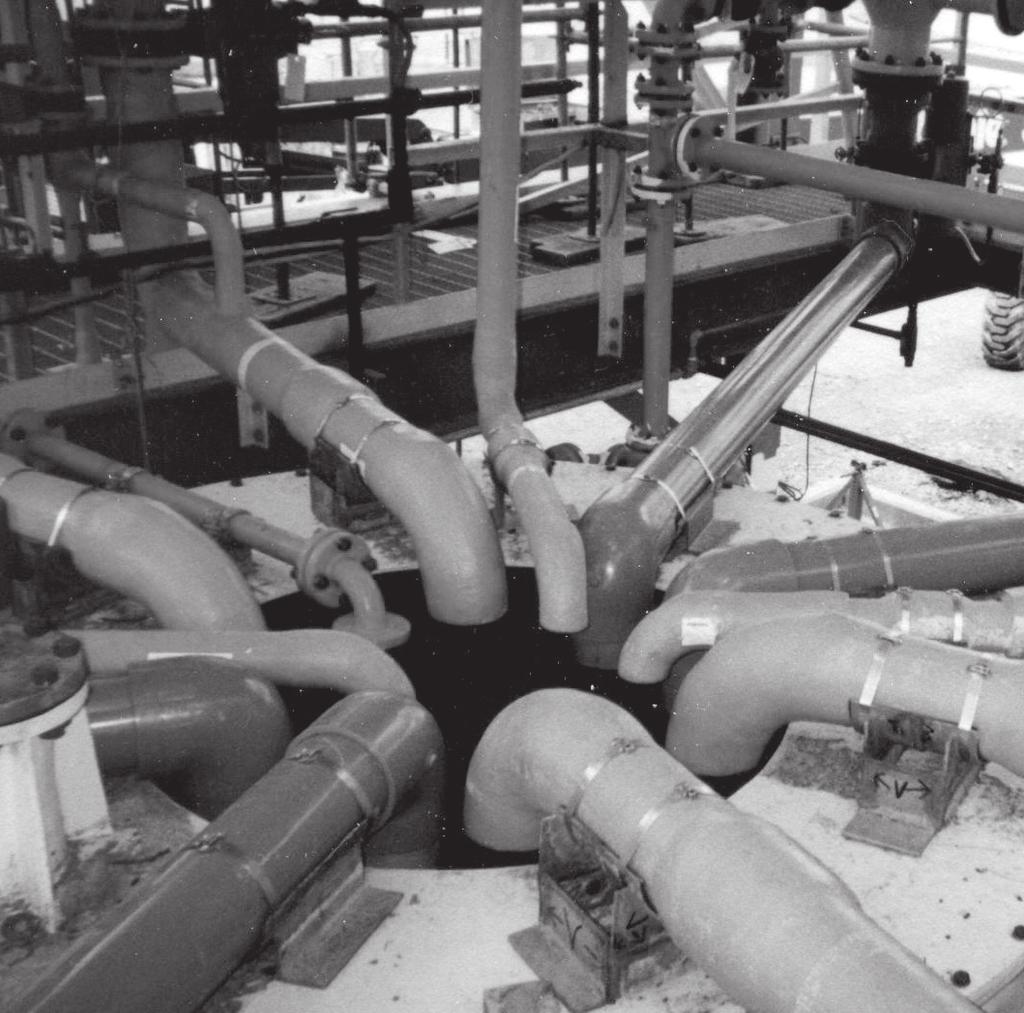
IntegraHeader. The Long-Term Chlorine Header Solution FRP SOLUTIONS MADE SIMPLER
 IntegraHeader The Long-Term Chlorine Header Solution FRP SOLUTIONS MADE SIMPLER What s The Problem? Conventional Systems Nozzle Severe attack on this chlorine header is evidenced by signs of leakage in
Powell. Sodium Hypochlorite Fiberglass Reinforced Plastic (FRP) Storage Tanks
 Storage Tanks") Powell Fabrication & Manufacturing Inc Last Updated: April 21, 2000 Sodium Hypochlorite Fiberglass Reinforced Plastic (FRP) Storage Tanks Part 1 General 1.01 Section includes A. Design and furnishing of
Powell Fabrication & Manufacturing Inc Last Updated: April 21, 2000 Sodium Hypochlorite Fiberglass Reinforced Plastic (FRP) Storage Tanks Part 1 General 1.01 Section includes A. Design and furnishing of
ENGINEERING CATALOGUE Version 1.4
 ENGINEERING CATALOGUE Version 1.4 Fiberglass Reinforced Composites Piping Tanks Equipment Engineering Services Table of Contents Commitment...3 Cooling Tower Piping...4 Tank & Vessels...5 FRP Piping &
Armor Plate Pipe Wrap
 Armor Plate Pipe Wrap Training and Certification Course Course Elements Section 1 - Pipeline Repair Systems Section 2 - Pipeline Coating Systems Section 3 - Surface Preparation Section 4 - Required Number
FRP PIPE, DUCT AND FITTINGS ENGINEERING GUIDE AND SPECIFICATIONS SIXTH EDITION
 FRP PIPE, DUCT AND FITTINGS ENGINEERING GUIDE AND SPECIFICATIONS SIXTH EDITION Ershigs, Inc. The Leader in FRP Systems Since 92, Ershigs, Inc. has been providing industry with quality metal products and
PRODUCT SPECIFICATIONS PULTRUDED GRATING AND TREADS SECTION PART 1 GENERAL
 PRODUCT SPECIFICATIONS PULTRUDED GRATING AND TREADS SECTION 06600 PART 1 GENERAL 1.1 Related Documents A. Drawings and general provisions of Contract, including General and Supplementary Conditions and
Filament Wound Architectural Columns: Blending Tradition with Technology
 Filament Wound Architectural Columns: Blending Tradition with Technology These unique patented filament wound columns help preserve the past with authentic, perfectly detailed structure that is architecturally
Warning. Warning. (2) Bondo knives one 4 and one 6 (can be purchased locally at automotive stores) 4 putty knife Acetone
 Bondo knives one 4 and one 6 (can be purchased locally at automotive stores) 4 putty knife Acetone") Installing UPP FRP Entry Seals on Fiberglass Sumps Introduction This document is meant as an installation overview for UPP FRP entry seals with fiberglass sumps and should be used in conjunction with the
Installing UPP FRP Entry Seals on Fiberglass Sumps Introduction This document is meant as an installation overview for UPP FRP entry seals with fiberglass sumps and should be used in conjunction with the
FIBERGLASS ROUND CONTROL DAMPERS. Model K-RD INTRODUCTION M.K. PLASTICS PROVIDES FOUR DAMPER MODELS K-RD SUGGESTED SPECIFICATION
 INTRODUCTION The M.K. Plastics series K-RD are manufactured to meet the needs of the odor control and corrosive HVAC industries by providing a corrosion-resistant FRP Damper that is used to regulate an
SAMPLE SPECIFICATIONS FOR PREFABRICATED FRP LIFT STATIONS
 SECTION 1-GENERAL 1 DESCRIPTION a. Scope of Work: i. Contractor shall furnish labor, materials, equipment, and performance of all work necessary or incidental to furnish and install a simplex/duple x-prefabricated
Time-Tested Fiberglass Piping Systems for Water Applications From Smith Fibercast. Bulletin No. C3320 November 1,2005
 Time-Tested Fiberglass Piping Systems for Water Applications From Smith Fibercast Bulletin No. C3320 November 1,2005 Choosing a Piping System FGS Smith Fibercast offers: Superior Material Performance -
ITEM NO SLIPLINING SANITARY SEWERS
 ITEM NO. 1100 SLIPLINING SANITARY SEWERS 1100.1 DESCRIPTION: Sliplining is accomplished by pulling or pushing liner pipe into existing sewers by use of mechanical or hydraulic equipment. Once in place,
Acetone is flammable; refer to the manufacturer s instructions for complete safety information.
 Installing UPP FRP Entry Seals on Fiberglass Sumps Introduction This document is meant as an installation overview for UPP FRP entry seals with fiberglass sumps and should be used in conjunction with the
Installation Guidelines for Flygt Pumps Pump Anchoring Recommendations
 Issued: Installation Guidelines for Flygt Pumps Pump Anchoring Recommendations Introduction Proper installation and anchorage of Flygt pumps and installation accessories is critical to limiting vibration
T TABLE OF CONTENTS SPUNWRAP COLLAR
 T TABLE OF CONTENTS SPUNWRAP COLLAR Underslab Air Duct with SpunWrap Collar Specification 2 SpunWrap Collar Installation Instructions 3 Physical Data for SpunWrap Collars 5 SpunWrap Field Installation
ENGINEERING SPECIFICATION NON-MAGNETIC RAISED FLOOR SYSTEM FOR MRI ROOM APPLICATIONS
 ENGINEERING SPECIFICATION NON-MAGNETIC RAISED FLOOR SYSTEM FOR MRI ROOM APPLICATIONS PULTRUDED DYNAFORM FIBERGLASS STRUCTURAL SHAPES FIBERGRATE COVERED TOP MICRO-MESH MOLDED GRATING WITH NON-MAGNETIC GRATING
SECTION VIBRATION CONTROLS FOR PLUMBING PIPING AND EQUIPMENT
 Page 220548-1 SECTION 220548 - PART 1 - GENERAL 1.1 RELATED DOCUMENTS A. Drawings and general provisions of the Contract, including General and Supplementary Conditions and Division 01 Specification Sections,
SECTION HANGERS AND SUPPORTS FOR PLUMBING
 SECTION 22 05 29 HANGERS AND SUPPORTS FOR PLUMBING PART 1 - GENERAL 1.1 RELATED DOCUMENTS A. Drawings and general provisions of the Contract, including General and Supplementary Conditions and Division
Bulletin No. A1300 November 1, Smith Fibercast GREEN THREAD Piping Systems
 Bulletin No. A1300 Novemer 1, 2006 Smith Fiercast GREEN THREAD Piping Systems PRODUCT GREEN THREAD pipe is filament wound using an amine-cured epoxy resin and fierglass and has a resinrich liner reinforced
HANGERS AND SUPPORTS FOR HVAC PIPING AND EQUIPMENT SECTION HANGERS AND SUPPORTS FOR HVAC PIPING AND EQUIPMENT
 13686.00 HANGERS AND SUPPORTS FOR HVAC PIPING AND EQUIPMENT 230529-1 SECTION 230529 - HANGERS AND SUPPORTS FOR HVAC PIPING AND EQUIPMENT 1.1 SUMMARY A. Section Includes: 1. Metal pipe hangers and supports.
B. Shop Drawings: Include plans, elevations, sections, details, and attachments to other work.
 SECTION 055116 - METAL FLOOR PLATE STAIRS PART 1- GENERAL 1.1 RELATED DOCUMENTS Drawings and general provisions of the Contract, including General and Supplementary Conditions and Division 01 Specification
SECTION VIBRATION CONTROLS FOR HVAC PIPING AND EQUIPMENT
 Page 230548-1 SECTION 230548 - PART 1 - GENERAL 1.1 RELATED DOCUMENTS A. Drawings and general provisions of the Contract, including General and Supplementary Conditions and Division 01 Specification Sections,
ENGINEERING SPECIFICATION. PULTRUDED PEDESTRIAN FIBERGLASS GRATING SAFE-T-SPAN T1210 VINYL ESTER and ISOPHTHALIC. October 25, 2004 Revision 1
 ENGINEERING SPECIFICATION PULTRUDED PEDESTRIAN FIBERGLASS GRATING SAFE-T-SPAN T1210 VINYL ESTER and ISOPHTHALIC 1 PART 1 - GENERAL 1.1 SCOPE OF WORK SECTION 06610 FIBERGLASS REINFORCED PLASTICS (FRP) FABRICATIONS
TAMDID PIPES GRP MANHOLE BROCHURE
 TAMDID PIPES GRP MANHOLE BROCHURE 1) Types & Description of Manholes: Tamdid Pipes offer two types of Manholes; Structural and Liner Manholes: a. Structural Manholes Tamdid Pipes offers concentric and
B. Fiberglass for construction in back lot easements placed on cast-in-place base.
 Section 02083 PART 1 G E N E R A L 1.01 SECTION INCLUDES A. Fiberglass manholes for unpaved areas placed on top of a precast base to form a manhole. B. Fiberglass for construction in back lot easements
ENGINEERING SPECIFICATION PULTRUDED DYNAFORM FIBERGLASS STRUCTURAL SHAPES FIBERGRATE MOLDED GRATING WITH GRATING PEDESTALS. January 24,
 ENGINEERING SPECIFICATION PULTRUDED DYNAFORM FIBERGLASS STRUCTURAL SHAPES FIBERGRATE MOLDED GRATING WITH GRATING PEDESTALS January 24, 2014 06600-1 SECTION 06610 FIBERGLASS REINFORCED PLASTICS (FRP) FABRICATIONS
CERAM CORE Abrasion Resistant Piping for Power Generation Applications
 Manual No. A1700 July 1, 2005 SMITH FIBERCAST CERAM CORE Abrasion Resistant Piping for Power Generation Applications Long Lasting Abrasion Resistant Lightweight CERAM CORE Pipe Outlasts carbon steel, cast
1. Temperature Change: 120 deg F (67 deg C), ambient; 180 deg F (100 deg C), material surfaces.
, ambient; 180 deg F (100 deg C), material surfaces.") SECTION 05500- METAL FABRICATIONS PART 1 - GENERAL 1.1 RELATED DOCUMENTS A. Drawings and general provisions of the Contract, including General and Supplementary Conditions and Division 01 Specification
SECTION 05500- METAL FABRICATIONS PART 1 - GENERAL 1.1 RELATED DOCUMENTS A. Drawings and general provisions of the Contract, including General and Supplementary Conditions and Division 01 Specification
Ceram Core Product Data
 Ceram Core Product Data Product Name 14/15 CHEMICAL & INDUSTRIAL Applications Bottom Ash Wet Fly Ash Vanadium Ore Slurries Potash Tailings Zinc Tailings Taconite Tailings Heavy Salt Slurries Uranium Ore
Engineering Branch Assets Delivery Group
 F.1 SCOPE This Technical Specification shall apply to Fibre Reinforced Plastics or Glass Reinforced Plastics (hereinafter referred to as FRP or GRP) structures and the materials used in their manufacture,
SECTION HANGERS AND SUPPORTS FOR PLUMBING PIPING AND EQUIPMENT
 SECTION 220529 HANGERS AND SUPPORTS FOR PLUMBING PIPING AND EQUIPMENT PART 1 - GENERAL 1.1 RELATED DOCUMENTS A. Drawings and general provisions of the Contract, including General and Supplementary Conditions
San Antonio Water System Standard Specifications for Construction ITEM NO. 848 SANITARY SEWERS
 ITEM NO. 848 SANITARY SEWERS 848.1 DESCRIPTION: This item shall govern the furnishing, installation and jointing of sanitary sewer pipe of the size and type specified by the project's plans and specifications.
ENGINEERING SPECIFICATION PULTRUDED FIBERGLASS GRATING SAFE-T-SPAN HIGH LOAD CAPACITY (47% OPEN AREA) VINYL ESTER. January 24,
 VINYL ESTER. January 24,") ENGINEERING SPECIFICATION PULTRUDED FIBERGLASS GRATING SAFE-T-SPAN HIGH LOAD CAPACITY (47% OPEN AREA) VINYL ESTER January 24, 2014 06610-1 SECTION 06610 FIBERGLASS REINFORCED PLASTICS (FRP) FABRICATIONS
ENGINEERING SPECIFICATION PULTRUDED FIBERGLASS GRATING SAFE-T-SPAN HIGH LOAD CAPACITY (47% OPEN AREA) VINYL ESTER January 24, 2014 06610-1 SECTION 06610 FIBERGLASS REINFORCED PLASTICS (FRP) FABRICATIONS
Pultruded Grating. ADDED SAFETY - durable grit surface, permanently bonded, and baked to the grating surface, for a safe, slip-resistant walkway.
 Pultruded Grating Combining corrosion resistance, long life, and a maintenance-free design, our pultruded grating is superior to conventional metals. This advanced grating is also lightweight and easy
SECTION HIGH DENSITY POLYETHYLENE PIPE AND FITTINGS
 SECTION 02620 PART 1 GENERAL 1.1 SCOPE OF WORK A. Furnish all labor, materials, equipment, and incidentals required to install High Density Polyethylene (HDPE) pressure pipe, fittings, and appurtenances
SECTION HIGH DENSITY POLYETHYLENE PIPE AND FITTINGS (PRESSURE PIPE)
") SECTION 02623 HIGH DENSITY POLYETHYLENE PIPE AND FITTINGS (PRESSURE PIPE) PART 1 - GENERAL 1.1 SCOPE OF WORK A. Furnish all labor, materials, equipment and incidentals required and install high density
SECTION 02623 HIGH DENSITY POLYETHYLENE PIPE AND FITTINGS (PRESSURE PIPE) PART 1 - GENERAL 1.1 SCOPE OF WORK A. Furnish all labor, materials, equipment and incidentals required and install high density
1.2 Reference Standard: NOFMA - National Oak Flooring Manufacturers Association Grading Standards.
 WOOD FLOORING GENERAL INFORMATION 1.1 This section applies to factory finished wood strip flooring. 1.2 Reference Standard: NOFMA - National Oak Flooring Manufacturers Association Grading Standards. 1.3
FIBERBOND DECK DRAINS
 ENGINEERED COMPOSITE PIPING SYSTEMS DECK DRAINS www.fiberbond.com www.futurepipe.com DRAIN SERIES: Drain Selection and Installation Guide The drains contained in this booklet are available in the following
SECTION HANGERS AND SUPPORTS FOR PLUMBING PIPING AND EQUIPMENT
 Page 220529-1 SECTION 220529 - PART 1 - GENERAL 1.1 RELATED DOCUMENTS A. Drawings and general provisions of the Contract, including General and Supplementary Conditions and Division 01 Specification Sections,
B. Shop Drawings: Include plans, elevations, sections, details, and attachments.
 SECTION 055119 - METAL GRATING STAIRS PART 1 - GENERAL 1.1 RELATED DOCUMENTS A. Drawings and general provisions of the Contract, including General and Supplementary Conditions and Division 01 Specification
Fiberstrut Parts Catalogue
 Fiberstrut s Catalogue 1 Technical Information Fiberstrut Fabrication The installation of fiberglass channels and accessories is similar to the installation of metallic channels and accessories. All standard
Stainless Steel Aeration Equipment Specification
 Section 15 Stainless Steel Aeration Equipment Specification Part 1 - General 1.01 Description A. Scope of Work 1. Furnish, install and test aeration system including air mains, drop pipes, valves, expansion
When a standard or other referenced document referred to in this specification is superseded by an approved revision, the revision shall apply.
 I. References When a standard or other referenced document referred to in this specification is superseded by an approved revision, the revision shall apply. II. Listing The conduit shall be listed by
GENERAL SPECIFICATION FOR FIRE RATED APPLICATIONS
 I N SULROCK FIRE RATED METAL PANELS GENERAL SPECIFICATION FOR FIRE RATED APPLICATIONS 1. GENERAL 1.1. Summary Fire-rated panels as shown on the drawings shall be INSULROCK brand panels as supplied by Green
INSTALLATION INSTRUCTIONS B407-PP SERIES SINGLEWALL TANK SUMP
 INSTALLATION INSTRUCTIONS B407-PP SERIES SINGLEWALL TANK SUMP Tank Sump Body Tongue and Groove Joint (pour in place) Base Lamination Joint S. Bravo Systems, Inc. 2929 Vail Ave. - Commerce, CA 90040 (323)
When a standard or other referenced document referred to in this specification is superseded by an approved revision, the revision shall apply.
 I. References When a standard or other referenced document referred to in this specification is superseded by an approved revision, the revision shall apply. II. Listing The conduit shall be listed by
Corrstop Dual Laminate Equipment. Corrstop. R CS Dual Laminate Equipment
 SPECIFICATION: Corrstop Dual Laminate Equipment Corrstop R CS Dual Laminate Equipment CUSTOMER / PROJECT: REQUIREMENTS 1.0 GENERAL Dual laminate equipment shall be manufactured by Composites USA, Inc.,
SPECIFICATION FIBERGLASS REINFORCED PLASTIC LIQUID CHEMICAL STORAGE TANKS
 FIBERGLASS REINFORCED PLASTIC LIQUID CHEMICAL STORAGE TANKS PART 1. GENERAL 1.1 WORK INCLUDED A. This section covers the work necessary to design, manufacture and supply stationary chemical storage tanks
Glass Steel, InC. 1. Fiberglass Composite Troughs. Elmira, CA Flat Bottom Curved Troughs
 Glass Steel, InC. 1 Fiberglass Composite Troughs Elmira, CA Flat Bottom Curved Troughs Glass Steel, InC. 2 Fiberglass composite troughs Glass-Steel, Inc. manufactures a proprietary system of composite
ENGINEERING SPECIFICATION PULTRUDED HIGH LOAD CAPACITY (HI) SAFE-T-SPAN FIBERGLASS GRATING. January 24,
 SAFE-T-SPAN FIBERGLASS GRATING. January 24,") ENGINEERING SPECIFICATION PULTRUDED HIGH LOAD CAPACITY (HI) SAFE-T-SPAN FIBERGLASS GRATING January 24, 2014 06610-1 SECTION 06610 FIBERGLASS REINFORCED PLASTICS (FRP) FABRICATIONS PULTRUDED HIGH LOAD CAPACITY
ENGINEERING SPECIFICATION PULTRUDED HIGH LOAD CAPACITY (HI) SAFE-T-SPAN FIBERGLASS GRATING January 24, 2014 06610-1 SECTION 06610 FIBERGLASS REINFORCED PLASTICS (FRP) FABRICATIONS PULTRUDED HIGH LOAD CAPACITY
Daytona Beach Pier Building Renovation Jun 2010
 SECTION 15060 - HANGERS AND SUPPORTS PART 1 - GENERAL 1.1 RELATED DOCUMENTS A. Drawings and general provisions of the Contract, including General and Supplementary Conditions and Division 1 Specification
DOUBLE CONTAINMENT DESIGN & INSTALLATION GUIDE
 DC-3-0604 Spears Double Containment Systems are engineered for ease of installation and lower associated installation costs. Complete systems include all necessary components - carrier pipe, containment
SECTION FRP GRATING, HANDRAIL, AND SUPPORTS
 PART 1 GENERAL 1.01 SCOPE OF WORK A. The Contractor shall furnish, fabricate (where necessary), and install all fiberglass reinforced plastic (FRP) items, with all appurtenances, accessories and incidentals
Style 204 EPS Product Specification
 Style 204 EPS Product Specification 1.0 Application The Style 204 EPS is used in rigid piping systems to compensate for axial, lateral, torsional and angular movement and misalignment due to thermal expansion
SECTION FLAT WALK-ON TYPE ALGAE CONTROL/LAUNDER COVERS
 PART 1 GENERAL 1.01 THE REQUIREMENT SECTION 11301 FLAT WALK-ON TYPE ALGAE CONTROL/LAUNDER COVERS A. The contractor shall furnish and install complete Flat Walk-On Algae Control/Launder Covers as shown
ITW INSULATION SYSTEMS
 ITW INSULATION SYSTEMS 1SCOPE TRYMER RIGID POLYISOCYANURATE INSULATION IN LIQUEFIED NATURAL GAS APPLICATIONS (-260 F) 1.1 This guideline covers the installation of Trymer* Rigid Polyisocyanurate Insulation
Series 4000 Fiberglass Pipe and Fittings
 FIBERGLASS PIPE GROUP Bondstrand Product Data with guide specification Series 4000 Fiberglass Pipe and Fittings for corrosive industrial service 2-6 installs with no shaving required Uses and applications
Bondstrand Series 3000A Fiberglass Pipe for General Industrial Service
 Bondstrand Series 3000A Fiberglass Pipe for General Industrial Service Uses and Applications Alcohol solutions Boiler feed water Bridge, roof and floor drains Brine and brackish water Chemical process
Installation Instructions
 Warning: Do not remove outer shrink wrapping from the Fire Rated Foam stick until you have read and understand the FULL instructions for proper installation. Failure to follow these directions may degrade
40'-0" PIPE SUPPORT (TYP.) (SEE DWG. NO. SK-2 OR DWG. NO. SK-4)
 (SEE DWG. NO. SK-2 OR DWG. NO. SK-4)") SK-1 STANDARD LENGTH 4.301 40'-0" A 6" 2'-0" 9'-0" 9'-0" 9'-0" 9'-0" 2'-0" A 3" OF EXPOSED AT EACH END OF PIPE. PIPE SUPPORT (TYP.) (SEE DWG. NO. SK-2 OR DWG. NO. SK-4) EXPOSED PIPE MINIMUM GAUGE AND THICKNESS
SK-1 STANDARD LENGTH 4.301 40'-0" A 6" 2'-0" 9'-0" 9'-0" 9'-0" 9'-0" 2'-0" A 3" OF EXPOSED AT EACH END OF PIPE. PIPE SUPPORT (TYP.) (SEE DWG. NO. SK-2 OR DWG. NO. SK-4) EXPOSED PIPE MINIMUM GAUGE AND THICKNESS
Industrial Fiberglass Specialties, Inc. 521 Kiser Street Dayton, OH Tel: Fax:
 08-16-2007 Page #1 of 6 Industrial Fiberglass Specialties pipe is filament wound and, therefore, has different thermal expansion in the hoop and axial direction. In the hoop direction, the thermal expansion
Diffused Aeration Piping Equipment
 1.0 General 1.1. The specifications in this section include all components of the Diffused Aeration System with the exception of the individual diffuser units. Refer to additional specification sections
ENGINEERING SPECIFICATION PULTRUDED DYNADECK INTERLOCKING FLOORING
 ENGINEERING SPECIFICATION PULTRUDED DYNADECK INTERLOCKING FLOORING January 24, 2014 06610-1 SECTION 06610 FIBERGLASS REINFORCED PLASTICS (FRP) FABRICATIONS PULTRUDED FIBERGLASS INTERLOCKING FLOORING PART
SECTION COMMON WORK RESULTS FOR FIRE SUPPRESSION
 Page 210500-1 SECTION 210500 - PART 1 - GENERAL 1.1 RELATED DOCUMENTS A. Drawings and general provisions of the Contract, including General and Supplementary Conditions and Division 01 Specification Sections,
Bondstrand Series 3000 Fiberglass Pipe for General Industrial Service
 Bondstrand Series 3000 Fiberglass Pipe for General Industrial Service Uses and Applications Boiler feed water Bridge, roof and floor drains Brine and brackish water Chemical process piping Cooling water
NORTH HARRIS COUNTY REGIONAL WATER AUTHORITY PIPE HANGERS, Section PIPE HANGERS, SUPPORTS, AND RESTRAINTS
 PART 1 GENERAL 1.01 SUMMARY Section 15140 PIPE HANGERS, This Section includes the furnishing and subsequent installation of: A. Pipe and equipment hangers, supports, and associated anchors B. Equipment
FIBERGLASS/RESIN-INFUSED ARCHITECTURAL PRODUCTS
 FIBERGLASS/RESIN-INFUSED ARCHITECTURAL PRODUCTS Fiberglass/Resin-Infused Columns: Blending Tradition with Technology At Pacific, we are committed to preserving the past with authentic, perfectly detailed
Protective Industrial Polymers - USA Manufacturer s Specification February 11, 2015
 This specification covers InhibiChem SR-GF-L Enhanced Chemical and Solvent-Resistant Glass-Flake Reinforced Steel Tank Lining System. This system consists of a vinyl ester primer, and two troweled coats
LS 486 / GLASS MAT REINFORCED SYSTEM A LAVALINE - SERIES 48 SYSTEM / Vinyl Ester CONCRETE & MASONRY SURFACES
 LS 486 / GLASS MAT REINFORCED SYSTEM / Vinyl Ester CONCRETE & MASONRY SURFACES The LS-486 system may be installed on various substrates, including carbon and stainless steel and concrete and other masonry
ASME B31.3 Process Piping
 ASME B31.3 Process Piping Charles Becht IV, PhD, PE Don Frikken, PE Instructors BECHT ENGINEERING COMPANY, INC. Nonmetallic Piping - 1 Piping Development Process 1. Establish applicable system standard(s)
Remember, on shop drawings for elastomeric bearings (Method B) to verify: 1. Vulcanize pad to sole plate - adhesives (epoxies) are unacceptable;
 to verify: 1. Vulcanize pad to sole plate - adhesives (epoxies) are unacceptable;") Handwritten: CIRCULATE 2-16/95 Engineers - Remember, on shop drawings for elastomeric bearings (Method B) to verify: 1. Vulcanize pad to sole plate - adhesives (epoxies) are unacceptable; 2. Pad orientation
Handwritten: CIRCULATE 2-16/95 Engineers - Remember, on shop drawings for elastomeric bearings (Method B) to verify: 1. Vulcanize pad to sole plate - adhesives (epoxies) are unacceptable; 2. Pad orientation
. SECTION HANGERS AND SUPPORTS
 . SECTION 230529 - HANGERS AND SUPPORTS PART 1 - GENERAL 1.1 RELATED DOCUMENTS A. Drawings and general provisions of the Contract, including General and Supplementary Conditions and Division I Specification
05510: TAPERED STEEL TROLLEY POLES AND ACCESSORIES
 PART 1 GENERAL 1.01 DESCRIPTION A. The Vendor shall fabricate, furnish, test and deliver tapered steel trolley poles, including base plates, reinforced hand holes, anchor bolts, nuts and washers, and accessories
FRP Specifications. Section Fiberglass Reinforced Polymer (FRP) Hollow Core Building Panels Products and Fabrications REVISED 11.
 Hollow Core Building Panels Products and Fabrications REVISED 11.") FRP Specifications Section 06 70 00 Fiberglass Reinforced Polymer (FRP) Hollow Core Building Panels Products and Fabrications REVISED 11.2016 BRISTOL FACILITY 400 Commonwealth Ave., P. O. Box 580, Bristol,
FRP Specifications Section 06 70 00 Fiberglass Reinforced Polymer (FRP) Hollow Core Building Panels Products and Fabrications REVISED 11.2016 BRISTOL FACILITY 400 Commonwealth Ave., P. O. Box 580, Bristol,
Double Containment DESIGN & INSTALLATION GUIDE TECHNICAL INFORMATION. Visit our web site
 Double DESIGN & INSTALLATION GUIDE TECHNICAL INFORMATION Visit our web site www.spearsmfg.com 1326 The information contained in this publication is based on current information and Product design at the
ITW INSULATION SYSTEMS
 ITW INSULATION SYSTEMS 1SCOPE TRYMER RIGID POLYISOCYANURATE INSULATION IN LIQUEFIED NATURAL GAS APPLICATIONS (Cryogenic to -70 F) 1.1 This guideline covers the installation of TRYMER Rigid Polyisocyanurate
FABRICATED STEEL PIPE AND SPECIALS
 SECTION 02420 - PART 1 -- GENERAL 1.1 WORK OF THIS SECTION A. The WORK of this Section includes providing fabricated steel pipe, specials and connections to new and existing piping. Polyurethane and fusion
Installation Guide. Rain Screen Panel System
 Installation Guide Rain Screen Panel System Main Office 6860 South Abbott Road Orchard Park, New York 14127 tel 716.649.7490 toll free 1.888.214.3655 www.bostonvalley.com General Inquiries info@bostonvalley.com
SECTION ALUMINUM HANDRAIL SYSTEMS
 SECTION 05520 ALUMINUM HANDRAIL SYSTEMS PART 1 - GENERAL 1.01 SUMMARY A. Section includes aluminum handrails and railings. B. Related Work: 1. Section 03300 - Cast-in-Place Concrete C. References: 1. American
SECTION METAL FLOOR PLATE STAIRS
 SECTION 05513 - METAL FLOOR PLATE STAIRS PART 1 - GENERAL 1.1 RELATED DOCUMENTS A. Drawings and general provisions of the Contract, including General and Supplementary Conditions and Division 01 Specification
Preassembled steel stairs with concrete-filled treads.
 SECTION 055113 - PART 1 - GENERAL 1 RELATED DOCUMENTS Drawings and general provisions of the Contract, including General and Supplementary Conditions and Division 01 Specification Sections, apply to this
SPECIFICATIONS - DETAILED PROVISIONS Section Stainless Steel Sluice Gates C O N T E N T S
 SPECIFICATIONS - DETAILED PROVISIONS Section 11294 - Stainless Steel Sluice Gates C O N T E N T S PART 1 - GENERAL... 1 1.01 SUMMARY... 1 1.02 REFERENCES... 1 1.03 DEFINITIONS... 1 1.04 DESIGN REQUIREMENTS...
SUPPORT AND ANCHORS SECTION 15090
 SUPPORT AND ANCHORS SECTION 15090 PART 1 GENERAL 1.1 DESCRIPTION OF WORK A. Work included in this Section: Materials, equipment, fabrication, installation and tests in conformity with applicable codes
ENGINEERING SPECIFICATION FIBERGRATE 1 INCH DEEP MICRO-MESH MOLDED GRATING SECTION 06610
 ENGINEERING SPECIFICATION FIBERGRATE 1 INCH DEEP MICRO-MESH MOLDED GRATING SECTION 06610 PART 1 - GENERAL 1.1 SCOPE OF WORK FIBERGLASS REINFORCED PLASTICS (FRP) FABRICATIONS 1 INCH DEEP MICRO-MESH MOLDED
Union County Vocational - Technical Schools Scotch Plains, New Jersey
 SECTION 092216 - NON-STRUCTURAL METAL FRAMING PART 1 - GENERAL 1.1 RELATED DOCUMENTS A. Drawings and general provisions of the Contract, including General and Supplementary Conditions and Division 01 Specification
1.2 The Engineer shall select appropriate sections of the specification to ensure that the specification is comprehensive for specified work.
 STAC Coating System Specification & Installation Guide 1.0 Scope 1.1 This specification may be used for the priming, caulking and wrapping with the STAC Petrolatum Coating System of any of the following
SECTION GLASS UNIT MASONRY ASSEMBLIES
 PART 1 GENERAL 1.01 SCOPE OF WORK A. The Contractor shall furnish and install all materials, labor, equipment and incidentals required to install glass unit masonry as shown on the contract drawings and
FIRE STATION 55 June 14, 2010
 SECTION 15250 MECHANICAL INSULATION PART 1 - GENERAL 1.01 DESCRIPTION A. Work Includes 1. Insulation of Domestic Water Piping. 2. Pipe Insulation of refrigerant piping. 3. Insulation of ductwork. 4. Aluminum