Department of Civil and Environmental Engineering The University of Michigan College of Engineering
|
|
|
- Preston Collins
- 6 years ago
- Views:
Transcription

1 PERFORMANCE-BASED PLASTIC DESIGN OF SEISMIC RESISTANT SPECIAL TRUSS MOMENT FRAMES by Shih-Ho Chao Subhash C. Goel Department of Civil and Environmental Engineering The University of Michigan College of Engineering Ann Arbor, MI
2 May 2006 Research Report UMCEE PERFORMANCE-BASED PLASTIC DESIGN OF SEISMIC RESISTANT SPECIAL TRUSS MOMENT FRAMES by Shih-Ho Chao Subhash C. Goel A report on research sponsored by Nabih Youssef & Associates Structural Engineers, and NUCOR Research and Development Department of Civil and Environmental Engineering The University of Michigan College of Engineering Ann Arbor, MI
3 ACKNOWLEDGEMENT This study was made possible by a generous financial support provided by Nabih Youssef & Associates Structural Engineers, and NUCOR Research and Development. The senior author also received a stipend from the G. S. Agarwal Fellowship Fund at the Department of Civil & Environmental Engineering while working on this project. The authors acknowledge the contribution of Dr. Gustavo Parra-Montesinos and Dr. K.Y. Kim to the experimental phase of this study (Chapter 3). The opinions and views expressed in the report are solely those of the authors and do not necessarily reflect those of the sponsors. ii
4 PERFORMANCE-BASED PLASTIC DESIGN OF SEISMIC RESISTANT SPECIAL TRUSS MOMENT FRAMES EXECUTIVE SUMMARY Special Truss Moment Frame (STMF) is a relatively new type of steel structural system that was developed for resisting forces and deformations induced by severe earthquake ground motions. The system dissipates earthquake energy through ductile special segments located near the mid-span of truss girders. STMFs generally have higher structural redundancy compared to other systems because four plastic hinges can form in the chords of one truss girder. The redundancy can be further enhanced if web members are used in the special segments. Simple connection details are adequate for girder-to-column moment connections. Another advantage of using STMF system is that the truss girders can be efficiently used over longer spans and higher overall structural stiffness can be achieved by using deeper girders. In addition, the open-webs can easily accommodate mechanical and electrical ductwork. As a consequence, this system is gaining popularity in the U.S., especially for hospital and commercial buildings. Research work carried out during the Nineties led to the formulation of design code provisions. However, current design practice generally follows elastic analysis procedures to proportion the frame members. Therefore, it is possible that story drifts and yielding in the special segments may not be uniformly distributed along the height of the structure and may be concentrated in a few floors causing excessive inelastic deformations at those levels. Thus, the intended deformation limits and yield mechanism may not be achieved when an STMF is subjected to strong earthquakes. In the first phase of the study an experimental program was conducted to investigate the ductility and plastic rotation capacity of chord members consisting of double channel sections for the special segments. A total of seven specimens were tested under reversed iii
5 cyclic bending. These specimens represent half length of a chord member of open Vierendeel segment of an STMF. The testing was undertaken to determine the influence of some detailing parameters, such as compactness, stitch spacing, lateral supports and end connections, on the ductility and hysteretic behavior. In the second phase of the study a Performance-Based Plastic Design (PBPD) procedure based on energy and plastic design concepts was applied to STMFs. The design approach was originally developed and successfully applied to steel moment frames. The procedure begins by selecting a desired yield mechanism for the structure. The design base shear and lateral forces are determined from spectral energy for a given hazard level needed to push the structure in the yielded state up to a selected target drift. The frame members are then designed by following the plastic design method in order to develop the needed strength and the intended yield mechanism. Two 9-story STMFs, representing the class of essential facilities (i.e., hospital buildings) as well as ordinary office/residential occupancy type, were designed by using the proposed procedure. For ordinary building type the target drifts of 2% and 3% for 10% in 50 years and 2% in 50 years design hazard levels, respectively, were chosen. The corresponding numbers for essential building were 1.5% and 2.25%. Design spectral values were based on NEHRP Provisions for the San Francisco site. After the final design work was completed, inelastic pushover and dynamic analyses were conducted to study the response and ductility demands of the frames. Nine 10% in 50 years and five 2% in 50 years SAC Los Angeles region ground motions representing the two design hazard levels were used for the nonlinear dynamic analyses. The results of the analyses were studied to validate the design procedure, and to compare the chord member ductility demands with the capacities as determined from the testing work on built-up double channel specimens. The study parameters included: location of yielding, maximum plastic rotation in chord members, maximum relative story shear distribution, maximum interstory drift, and peak floor accelerations. iv
6 TABLE OF CONTENTS ACKNOWLEDGEMENT... ii EXECUTIVE SUMMARY... iii LIST OF TABLES... viii LIST OF FIGURES...x CHAPTER 1. INTRODUCTION Background Design Criteria for STMFs Remarks on STMF Design and Research Scope Organization of the Report PERFORMANCE-BASED PLASTIC DESIGN PROCEDURE FOR STMF USING PRE-SELECTED TARGET DRIFT Introduction Performance-Based Plastic Design Procedure Design Lateral Forces Design Base Shear Conventional Method Proposed Energy-Based Procedure Proposed Design Procedure Pre-Selected Yield Mechanism Proportioning of Chord Members of the Special Segments Vierendeel Special Segments Vierendeel Special Segments with intermediate vertical v
7 members Design of Members outside the Special Segments Exterior columns with associated truss girders Interior columns with associated truss girders Proposed modification of the expected vertical nominal shear strength in special segment ( V ne ) TESTING OF DOUBLE CHANNEL BUILT-UP COMPONENTS UNDER REVERSED CYCLIC BENDING Introduction Experimental Program AISC-LRFD Provisions for Steel Channels Test Program Test Specimens Experimental Results Overall Behavior of Specimens C1 thru C Specimen C7 with Innovative Reinforcing Method Comparison between Specimens C5, C6, and C Rotation Capacity and Design Recommendations Modeling of The Moment-Rotation Relationship FIRST PHASE INVESTIGATION Introduction Prototype Structure Modeling for Nonlinear Analyses Modeling of STMF Components Force-Deformation Relations and Component Models Gravity Loads and Seismic Masses Damping Earthquake Records Analysis Results of STMF Second Stage Study vi
8 4.6 Third Stage Study Conclusions from the First Phase Study SECOND PHASE INVESTIGATION Introduction Description of the Structure NEHRP 2000 Provisions Background Design Base Shear and Lateral Force Distribution NEHRP Design Response Spectrum and SAC Earthquake Records Design of 9-story Ordinary STMF Design Base Shear and Lateral Force Distribution Design of Chord Members in Special Segments Design of Members outside Special Segments Performance Evaluation of the 9-Story Ordinary STMF Design of the 9-story Essential STMF Design Base Shear and Lateral Force Distribution Design of Chord Members in the Special Segments Design of Members outside the Special Segments Performance Evaluation of the 9-Story Essential STMF Additional Note on The Design of STMFs SUMMARY AND CONCLUSIONS Summary Conclusions BIBLIOGRAPHY vii
9 LIST OF TABLES Table Ceu 2.1. Ductility reduction factor ( R = μ ) and its corresponding structural C y period range Properties of test specimens Rotation capacity of test specimens Floor weights for the design of STMF Design parameters in accordance with CBC (2001) Design parameters of proposed procedure for STMF Design parameters for STMF Design parameters of proposed procedure for STMF Sections of chord members of the study STMFs Design Parameters for 9-story ordinary STMF calculated according to NEHRP Design Parameters for the proposed procedure Distribution of Shear Proportioning Factor for the 9-Story ordinary STMF Design Lateral Forces for the 9-Story ordinary STMF (for two frames) Required Chord Member Strength and Selected Chord Member Sections Compactness Check for Chord Member Sections per AISC Seismic Provision Table I Design Forces for Elements outside Special Segments viii
10 5.8. Design Parameters for 9-story essential STMF calculated according to NEHRP Design Parameters for the proposed procedure Distribution of Shear Proportioning Factor for the 9-Story essential STMF Design Lateral Forces for the 9-Story essential STMF (for two frames) Required Chord Member Strength and Selected Chord Member Sections Compactness Check for Chord Member Sections per AISC Seismic Provision Table I Design Forces for Elements outside Special Segments (for one frame only) Steel weight calculation of ordinary STMF (one frame only) Steel weight calculation of essential STMF (one frame only) Relation between plastic rotation of chord members and story drift ratio of a typical STMF (Note: assuming the ratio of truss girder span to the length of special segment is 3.75) ix
11 LIST OF FIGURES Figure 1.1. STMF with different configurations of Special Segment (Basha, 1994) Mechanism of STMF with different Special Segment (Basha, 1994) Details of diagonally reinforced central portion to relocate the inelastic deformation away from column faces (Paulay and Priestley, 1992) Ductwork through a Vierendeel special segment opening of an STMF(Courtesy of John Hooper) A typical STMF with 2-panel Vierendeel special segments under construction(courtesy of John Hooper) Three selected story shear distributions in the first phase of study Structural idealized response application of principle of energy conservation Ductility reduction factors proposed by Newmark and Hall (1982) Modification factors for energy equation versus period Pre-selected yield mechanism of STMF with Vierendeel configuration of Special Segment One-bay frame with pre-selected yield mechanism for calculating required strength of chord members; note that the values of Fi and Fn are for one bay only One-bay frame with soft-story mechanism (Leelataviwat et al., 1999) Yield mechanism of STMF with multiple Vierendeel panels Free body diagram of an exterior columns and associated truss girder branches: (a) lateral forces acting to right side; (b) lateral force acting forces to left side...51 x
12 2.10. Free body diagram of an exterior columns and associated truss girder branches with concentrated gravity loadings on truss girders ( lateral forces acting to right side) Free body diagram of an interior columns and associated truss girder branches subjected to lateral forces to right Performance-based plastic design flowchart for STMF: determine design base shear and lateral force distribution Performance-based plastic design flowchart for STMF: element design Deformation of in chord of the Vierendeel special segment: (a) no chord end rotation; (b) free chord end rotation Moment-rotation relation of chord member Calculation ofv ne for two Vierendeel panels Calculation ofv ne for three Vierendeel panels Plastic rotation in chords of special segments in STMFs (Parra et al., 2006) (a) Test setup (Parra et al., 2006) (b) Overall view of test setup and test specimen Loading protocol Detail of Specimen C Detail of Specimen C Detail of Specimen C Detail of Specimen C Detail of Specimen C (a) Detail of Specimen C (b) Welding detail of Specimen C Moment versus drift response of Specimens C1-C6 (Parra et al., 2006) (a) Lateral-torsional buckling in Specimens C1 at 1.5% story drift; (b) Fracture of the channel leg in Specimen C xi
13 3.12. Lateral-torsional buckling in Specimens C2 at (a) 1.5% story drift; (b) 3.0% story drift Local buckling and fracture in Specimen C Lateral-torsional buckling in Specimens C3 at (a) 1.5% story drift; (b) 3.0% story drift (a) Cracking of gusset plate-channel connection and (b) fracture of channel in Specimen C3 during 3.5% story drift cycle Specimen C4: (a) Yielding pattern and local buckling at the second cycle of 3.0% story drift; (b) Fracture of channel during the third cycle to 3.0% story drift Specimen C5: (a) Yielding pattern and local buckling at the third cycle of 3.0% story drift; (b) Fracture of channel during the fourth cycle to 3.0% story drift Specimen C6: (a) Yielding pattern and local buckling at the fourth cycle of 3.0% story drift; (b) Fracture of channel during the second cycle to 3.5% story drift (a) Detail of Specimen C (b) Detail of the carbon woven mesh wrapping on Specimen C7 (unit: inches) Specimen C7: (a) Yielding pattern and local buckling at the fourth cycle of 3.0% story drift; (b) Fracture of channel during the second cycle to 3.5% story drift Lateral load versus story drift response of Specimen C Comparison of the reinforcing details and overall cyclic performance in Specimens C5, C6, and C Comparison of dissipated energy in Specimens C5, C6, and C Modeling of the backbone curve of Specimen C6 using bilinear curve Study building layout and STMFs in the first phase investigation Typical truss elevation Profile of study STMF Sections of STMF xii
14 4.5. Design special segment and truss member sections for STMF Rigid-plastic hinge model and corresponding moment-rotation relationship P-M interaction curves for Beam-Column elements Column component model: (a) General floor columns; (b) First floor columns Component model for chord members Component model for vertical members in a truss girder Component model for diagonal members in a truss girder Variation of damping ratio with structural period Design spectrum and LA 01 response spectra (Continued) Design spectrum and LA 09 response spectra (Continued) Design spectrum and LA 12 response spectra (Continued) Design spectrum and LA 13 response spectra (Continued) Design spectrum and LA 17 response spectra (Continued) Design spectrum and LA 19 response spectra Pushover response of STMF Maximum developed shears in special segments when STMF-1 was statically pushed to 2% roof drift Maximum developed shears in special segments for various ground motions (STMF-1) Maximum plastic hinge rotations in chord members (STMF-1) Percentage of dissipated hysteretic energy (STMF-1) (Continued) Percentage of dissipated hysteretic energy (STMF-1) (Continued) Percentage of dissipated hysteretic energy (STMF-1) Maximum interstory drift (STMF-1) Relative distributions of story shears (STMF-1) xiii
15 4.21. Axial force ratios in special segments for various ground motions (maximum value at each floor level was used to compare with nominal axial strength) Sections of the STMF-2 designed in the second stage of the first phase study (Note for study purposes only chord members were redesigned) Percentage of dissipated hysteretic energy (STMF-2) (Continued) Percentage of dissipated hysteretic energy (STMF-2) (Continued) Percentage of dissipated hysteretic energy (STMF-2) Maximum plastic hinge rotations in chord members (STMF-2) Comparison of maximum interstory drift between STMF-1 and STMF Pushover responses of three study frames designed by three different lateral force distributions in the third stage of the first phase study Maximum interstory drift of four study frames based on different lateral force distributions during La17 Northridge (Sylmar) ground motion Average maximum plastic rotations of chord members in special segments at each floor during La09 Landers (Yermo) ground motion Building plan and STMFs in the second phase investigation Elevation of study STMFs in the second phase investigation Acceleration, velocity, and displacement time histories of 10/50 SAC records (Continued) Acceleration, velocity, and displacement time histories of 10/50 SAC records (Continued) Acceleration, velocity, and displacement time histories of 10/50 SAC records (Continued) Acceleration, velocity, and displacement time histories of 10/50 SAC records (Continued) Acceleration, velocity, and displacement time histories of 10/50 SAC records Acceleration, velocity, and displacement time histories of 2/50 SAC records xiv
16 5.4. (Continued) Acceleration, velocity, and displacement time histories of 2/50 SAC records (Continued) Acceleration, velocity, and displacement time histories of 2/50 SAC records NEHRP 2000 design response spectrum Design spectrum and response spectra of SAC ground motions (LA Region) (Continued) Design spectrum and response spectra of SAC ground motions (LA Region) (Continued) Design spectrum and response spectra of SAC ground motions (LA Region) (Continued) Design spectrum and response spectra of SAC ground motions (LA Region) (Continued) Design spectrum and response spectra of SAC ground motions (LA Region) Forces acting on the interior column free body (9-story ordinary STMF) (a) Design Column Sections for the 9-story ordinary STMF (b) Design Special Segment and Truss Member Sections for the 9- story ordinary STMF Nonlinear Static Pushover Response of the 9-Story ordinary STMF Relative Story Shear Distributions obtained from Nonlinear Dynamic Analyses (9-story ordinary STMF) Maximum plastic hinge rotations in chord members for 9-story ordinary STMF subjected to 10%/50 and 2%/50 ground motions Maximum developed shears in special segments in the 9-story ordinary STMF subjected to 10%/50 and 2%/50 ground motions (a) Maximum Interstory Drift Distributions of the 9-Story ordinary STMF subjected to 10% in 50 year SAC Earthquake Records (LA Region) (a) (Continued) Maximum Interstory Drift Distributions of the 9-Story ordinary STMF subjected to 10% in 50 year SAC Earthquake Records (LA Region) xv
17 5.13. (b) Maximum Interstory Drift Distributions of the 9-Story ordinary STMF subjected to 2% in 50 year SAC Earthquake Records (LA Region) Mean value of maximum interstory drifts and corresponding target drifts for the 9-Story ordinary STMF Peak Floor Accelerations (10% in 50 year) and the NEHRP-specified Design Acceleration for Acceleration-Sensitive nonstructural components (a) Design Column Sections for the 9-story essential STMF (b) Design Special Segment and Truss Member Sections for the 9- story essential STMF Nonlinear Static Pushover Response of the 9-Story Essential STMF Relative Story Shear Distributions obtained from: (a) Nonlinear Dynamic Analyses of the 9-story essential STMF (Continued) Relative Story Shear Distributions obtained from: (b) Nonlinear Dynamic Analyses of the 9-story ordinary STMF; (c) Elastic Dynamic Analyses of the 9-story ordinary STMF (Continued) Relative Story Shear Distributions: (d) Legend Maximum plastic hinge rotations in chord members for 9-story essential STMF subjected to 10%/50 and 2%/50 ground motions Maximum developed shears in special segments in the 9-story essential STMF subjected to 10%/50 and 2%/50 ground motions (a) Maximum Interstory Drift Distributions of the 9-Story essential STMF subjected to 10% in 50 year SAC Earthquake Records (LA Region) (a) (Continued) Maximum Interstory Drift Distributions of the 9-Story essential STMF subjected to 10% in 50 year SAC Earthquake Records (LA Region) (b) Maximum Interstory Drift Distributions of the 9-Story essential STMF subjected to 2% in 50 year SAC Earthquake Records (LA Region) Mean value of maximum interstory drifts and corresponding target drifts for the 9-Story essential STMF xvi
18 5.23. Peak Floor Accelerations (10% in 50 year) and the NEHRP-specified Design Acceleration for Acceleration-Sensitive nonstructural components Comparison of the residual roof drifts (displacements) between 9-story ordinary and essential STMFs (Continued) Comparison of the residual roof drifts (displacements) between 9-story ordinary and essential STMFs xvii
19 - 1 - CHAPTER 1 Introduction 1.1 Background Seismic behavior of STMF system has been studied both analytically and experimentally by Goel et al. (Itani and Goel, 1991; Basha and Goel, 1994) at the University of Michigan during the past fifteen years and has been incorporated into the AISC Seismic Provisions for Structural Steel Buildings (AISC, 2005). This frame consists of truss frames with special segment designed to behave inelastically under severe earthquakes while the other members, including girder-to-column connections, outside the special segment remain essentially elastic. The special segment can be made with or without (Vierendeel) X-diagonal web members, as shown in Figure 1.1. When a STMF is subjected to seismic motions, the induced shear force in the middle of the joist girder is resisted primarily by the chord members and the web diagonals in the special segment. After yielding and buckling of the diagonal members, plastic hinges will form at the ends of the chord members. The yield mechanism of this structural system is the combination of yielding of all special segments in the frame plus the plastic hinges at the column bases, as shown in Figure 1.2. Comparison between STMF and frames with conventional truss girders as well as solid web beams has shown that STMF outperforms the others in terms of the energy-dissipation capacity, story drifts, and hysteretic behavior. The lateral design forces may also be smaller for STMF system (Itani and Goel, 1991).
20 - 2 - The first STMF system with X-diagonal special segment was first developed by Itani and Goel (Itani and Goel, 1991). Design of STMFs starts with designing the special segment. Based on capacity design approach, other elements are then designed to remain elastic under the shear forces in the middle of the joist girder generated by fully yielded and strain hardened special segments, along with other external forces. A similar concept was employed in reinforced concrete frames by Paulay and Priestley (1992), where they used a weak segment near the mid-span of beams, as shown in Figure 1.3. When the frame is subjected to reversed cyclic inelastic displacement, the central diagonally reinforced portion will behave like a coupling beam which is used to transfer shear between to walls. Because the shear in a coupling beam is transferred primarily by the diagonal concrete strut across the beam, the added diagonal reinforcement will be subjected to large inelastic tensile or compressive strains during a major earthquake. As a result, a very ductile behavior with excellent energy-dissipation capacity could be expected. Due to excellent behavior of STMFs observed from both experimental and analytic results, Basha and Goel (1994) developed another type of special segment by using a ductile Vierendeel segment without the diagonal members. A mathematical expression for the ultimate expected shear capacity of the special segment was derived by Basha (1994). Tests on subassemblages showed no pinching in the hysteretic loops with very stable and ductile behavior. All the inelastic deformations were confined to the special segments only, thus eliminating the possibility of damage in the other elements, such as girder-to-column connections. As a consequence, simple detailing without the need for
21 - 3 - ductility is used for the connections. Ireland (1997) studied the STMF system for low to moderate seismic regions where wind can be a significant design factor. STMFs were compared with conventional systems in those areas. The results of that study also showed superior performance of STMFs compared to the conventional truss system. Aslani (1998) studied the seismic behavior of STMFs under combined gravity and lateral loads. The results showed that STMF system designed for combined loads was able to perform satisfactorily in the event of a severe ground motion. Moreover, the overall seismic behavior with floor deck (not designed for composite action) was also investigated. Based on experimental and nonlinear dynamic analytical results, he suggested that the effect of composite action could be neglected in the dynamic analysis. That is because the composite action deteriorates rapidly under cyclic loading and after a few cycles the effect of composite action almost vanishes. If proper amount of shear connectors were used in the region of special segment, the composite action would lead to increased flexural capacity of the chord members. In that situation, Aslani suggested that, the effect of composite action between the chord member and floor deck should be accounted for the design of the members outside the special segments in order to ensure elastic behavior. Since the design of members outside the special segment is governed by the expected shear strength of the special segment, any increase in strength of the special segment also affects the design strength of members outside the special segments. Aslani suggested an increased chord strength equal to 0.65M, where p M p is the ultimate
22 - 4 - flexural strength of the composite section. Aslani also examined the reparability of STMF system by testing a repaired specimen. The results confirmed that, under the same loading history, the STMF can be retrofitted to the original strength and hysteretic response with minimum cost. Other advantages of using STMF system include: (1) The open-web floor framing can have longer span length and overall structural stiffness due to greater girder depth; (2) The open-webs can accommodate electrical conduits, plumbing and heating, and air-conditioning ductwork through the openings, which in turn results in greater ceiling height (Viest et al., 1997). Figure 1.4 shows the ductwork through openings in an STMF building and a typical STMF building structure is shown in Figure Design Criteria for STMFs The key points for designing an STMF as summarized in this section are based on the past research (Itani and Goel, 1991; Basha anf Goel, 1994; Leelataviwat and Goel, 1998a; Rai, Basha and Goel, 1998) and the AISC Seismic Provisions (AISC, 2005). 1) Special segment design criteria: The size of X-diagonal members and chord members in the special segment are selected based on the maximum vertical force resulting from the appropriate
23 - 5 - design earthquake load combination. The shear contribution from the X-diagonals is limited to 75% of the required shear V req. Chord members of the special segment are designed for the remaining 25% of the required shear which is resisted through the end plastic hinges. X-diagonal members are interconnected at point of crossing. b X-diagonal members are flat bars with 2. 5 t Chord angle sections must have b 52 t F y The length of the special segment is limited within 0.1 and 0.5 times the span length (AISC 12.2). The length-to-depth ratio of any panel in the special segment is to neither exceed 1.5 nor be less than 0.67 (AISC 12.2) The axial force in the chord members is not to exceed 0.45 times φ F y A g ( φ = 0. 9 ). Design of an STMF can be quite sensitive to the strength of elements in the special segments resulting in oversizing of the elements outside the special segment. For optimizing the chord members, built-up sections composed of double angles and plate should be used. 2) Design of members outside the special segment: Determine the expected vertical nominal shear strength, V ne, in the special segment
24 - 6 - according to AISC Seismic Provisions Eq. (12-1) for design of members outside the special segment: where ( ) 3.75RM L L V = E I + R P + 0.3P sin α (1.1) ( ) y nc s ne s 3 y nt nc Ls Ls R y = yield stress modification factor M nc = nominal flexural strength of the chord member of the special segment EI= s flexural elastic stiffness of the chord members of the special segment L = span length of the truss L s = length of the special segment P nt = nominal axial tension strength of diagonal members of the special segment P nc = nominal axial compression strength of diagonal members of the special segment α = angle of diagonal members with the horizontal The first two terms of Eq. (1.1) were derived based on Vierendeel special segment without web diagonals (Basha and Goel, 1994). The third term is needed only when the X-diagonal members are present. Design members outside the special segments using the gravity loads, expected vertical nominal shear strength in the special segments, V ne, and lateral forces needed to maintain equilibrium.
25 Remarks on STMF Design and Research Scope As mentioned earlier, the reason for using the maximum expected vertical shear strength, V ne, to design members outside special segment is to prevent other members from yielding. Experimental results have shown that well-detailed special segment members can sustain large inelastic deformation reversals without losing strength and stiffness. Therefore global structural stability and performance will not be compromised if inelastic activity is confined only to special segments. Unintended yielding or buckling of diagonal members or columns can result in undesirable response. As a matter of fact, testing on weak-column strong-beam steel frames has shown that columns exhibit poor hysteretic behavior with rapid strength and stiffness deterioration if the axial load exceeds 25% of the nominal axial yield strength (Schneider and Roeder, 1993). Unfortunately, such unintended poor seismic behavior cannot be effectively predicted and prevented by conventional seismic design methods. In particular, although the column design follows capacity design approach in an indirect way, the calculated design moments may not give actual distribution of moments when the yield mechanism is reached. In this regard, the design lateral forces acting on the frames should be increased appropriately to account for the fully yielded and strain hardened special segments at all floor levels. By using this treatment, the resulting distribution of moments in the columns will be more realistic and, in conjunction with the applicable gravity axial loads, the capacity design can be achieved. This approach was used in the PBPD design procedure for STMFs in this study. In recent years, seismic design has been gradually moving towards performance-based design approach, which is intended to produce structures with
26 - 8 - predictable and controlled seismic performance. To achieve this goal, knowledge of the ultimate structural behavior, such as nonlinear relations between forces and deformations, and yield mechanism of structural system are essential. Therefore, the desired global yield mechanism needs to be built into the design process. Recently, various performance-based design methods have been developed such as capacity spectrum approach for determining the design lateral loads, displacement-based design procedure, and energy-based design procedure (Rai, 2000). The energy-based design procedure uses the balance relation between the required elastic and inelastic work and the energy dissipated by structures to predict the drift level a structure may undergo when subjected to a specified seismic hazard level. If the drift can be accurately determined at the design stage, then damage can be controlled, thus intended performance is achieved. This approach, together with the plastic design procedure, has been successfully developed and validated using steel moment frames (Leelataviwat, Goel, and Stojadinović, 1999, Lee and Goel, 2001). In this report, the same procedure was employed to design STMFs with Vierendeel special segments, one with seven stories, and another with nine stories. Nonlinear static pushover and dynamic time history analyses were carried out. Performance evaluation of the frame responses was made in terms of interstory drift, chord member deformation, energy dissipation, absolute floor acceleration, and global performance. Chord members of STMFs tested previously were built-up sections made of double angles and a plate. These build-up sections generally have limited strength capacity. However, larger strength capacity may be needed for STMFs used for larger and taller
27 - 9 - buildings, such as for hospitals. Chord members made of double channel sections may be more suitable for use. In order to check the feasibility of using double channels for chord members, component tests were also carried out with various detailing configurations. The results were used to develop details to achieve adequate ductility. As a consequence, the STMFs studied in this report used double channel sections for chord members. 1.4 Organization of the Report This report is organized into six chapters. Details of each chapter are briefly described in the following. The overall proposed performance-based design procedure is presented in Chapter 2. A brief background regarding the design philosophy based on energy concept is also given, along with two design flowcharts. Chapter 3 describes the experimental results for double channel component tests under cyclic displacement reversals. Suggested detailing is given as derived from the test results. Chapter 4 presents the details of the design of a seven-story STMF. A preliminary design based on an earlier study of SMRF was examined using non-linear dynamic analyses and a refinement was made for this study. A revised equation for calculating the maximum expected vertical shear strength,, is proposed. The modeling details used V ne
28 in the Perform-2D program, as well as the ground motion records (10 % in 50 years and 2 % in 50 years SAC LA region ground motion) and the design spectra are given. Chapter 5 describes the design and performance evaluation of an ordinary and an essential nine-story STMF building based on non-linear pushover and dynamic analyses using some SAC LA region ground motions with 10% and 2% probability of exceedence in 50 years. The study parameters included: location of yield activity, maximum plastic hinge rotation in chord members, maximum relative story shear distribution, maximum interstory drifts, and peak floor accelerations. Chapter 6 presents a brief summary of the study and important conclusions and recommendations based on the results.
29 Special Segment Special Segment L L Figure 1.1 STMF with different configurations of Special Segment (Basha, 1994) F 4 F 4 F 3 F 3 Plastic Hinges Plastic Hinges F 2 F 2 F 1 F 1 Special Segment Special Segment Figure 1.2 Mechanism of STMF with different Special Segment (Basha, 1994)

30 Figure 1.3 Details of diagonally reinforced central portion to relocate the inelastic deformation away from column faces (Paulay and Priestley, 1992)


31 (a) (b) Figure 1.4 Ductwork through a Vierendeel special segment opening of an STMF (Courtesy of John Hooper)

32 Figure 1.5 A typical STMF with 2-panel Vierendeel special segments under construction (Courtesy of John Hooper)
33 CHAPTER 2 Performance-Based Plastic Design Procedure for STMF Using Pre-Selected Target Drift 2.1 Introduction It is most desirable that structures are proportioned to yield at locations which are most capable of deforming into inelastic range and sustaining large cyclic deformations. Yielding in columns should be avoided or minimized because of the difficulty in detailing for ductile response in the presence of high axial loads and because of the possibility that excessive column yielding may result in formation of story mechanism which may lead to cause collapse. Hence, for conventional special moment frames, capacity-design approach (strong column weak-beam) is usually employed to force plastic hinges to form at the beam ends. The strong column-weak beam design requirements in the current codes, however, do not guarantee that plastic hinging would not occur in the columns during major earthquake events (Paulay and Priestley, 1992; Lee 1996). Yielding in the columns may also be caused due to higher modes of vibration, particularly in the upper stories, as well as due to commonly used design methods which are based on elastic analysis and response results. The performance-based design procedure, as briefly described herein, is aimed at achieving predictable and controlled behavior of structures during design level seismic events. Three major factors are important in achieving this goal:
34 - 16-1) A design lateral force distribution which reflects realistic story shear distribution along the height of the structure when subjected to severe earthquakes. The triangular force distribution used in most design codes is derived from elastic analysis and may not be valid in the inelastic state. Therefore, a design lateral force distribution derived from nonlinear dynamic analysis results and calibrated by representative ground motion records is more appropriate for performance-based design procedure. 2) A predictable global yield mechanism so that the damage could be confined in pre-selected locations of the frame. In this regard, elastic design procedure cannot guarantee a predicable mechanism due to the predominantly inelastic nature of the structural response during severe earthquakes. Therefore, plastic design procedure is more suitable for purposes of performance-based seismic design because desirable yield mechanism is preselected. This design procedure was developed and successfully validated through nonlinear dynamic analyses for steel moment resistant frames (Leelataviwat, Goel and Stojadinović, 1999; Lee and Goel, 2001; Lee, Goel, and Chao, 2004). 3) A pre-selected target drift limit which can be incorporated at the design stage. To achieve the target building performance levels (such as immediate occupancy, collapse prevention, etc.) for selected earthquake hazard levels the story drift is a good design parameter. Therefore, a design base shear based on selected target drift level, ductility reduction factor, and structural ductility factor was used in this study. This design base shear was derived from modified energy equation and the proposed lateral force distribution (Leelataviwat, Goel and Stojadinović, 1999; Lee and Goel, 2001; Lee, Goel,
35 and Chao, 2004). The performance-based plastic design methodology which integrates the above factors is briefly presented in the following section for STMF with Vierendeel special segments. 2.2 Performance-Based Plastic Design Procedure Design Lateral Forces The design lateral forces are determined by using the shear distribution factor β i (Lee and Goel, 2001) obtained by nonlinear time-history analyses. However, the shear distribution factor was previously derived for moment frames. Therefore, β i was re-calibrated through nonlinear dynamic analyses for STMFs in this study (see Figure 2.1 as well as Chapter 4 for details) and can be expressed as: β V i i i i i = = V n wnh n n wh T (2.1) F wh n n n = V n j= 1 wh j j T (2.2)
36 Fi = ( βi β i + 1) Fn when i= n, βn+1 = 0 (2.3) where β is the shear distribution factor at level i; V and V respectively are the story i shear forces at level i and at the top (nth) level; w and w are the weights of the structure at level i and j, respectively; h and h are the heights of story level i and j i from ground, respectively; w is the weight of the structure at top level; h is the n height of top story level from ground; T is the fundamental period; F and F are the lateral forces applied at level i and top level n, respectively; V is the design base shear (see next step). j i i n j i n n Design Base Shear Conventional Method Design base shear in current seismic codes is commonly calculated by reducing the elastic strength demands to the inelastic strength demands using the response modification factors. These inelastic strength demands are further increased according to the importance of specific structures using occupancy importance factor. Generally, the design base shear is determined from the code prescribed design acceleration spectrum and can be expressed in the following form:
37 I V = CW s = C e W R (2.4) where C s is the seismic response coefficient calculated based on specific design code; C e is the design pseudo-acceleration coefficient; I is the occupancy importance factor; R is the response modification factor (= 7.0 for STMF; NEHRP, 2001); and W is the total seismic weight. After selecting the member sizes for required strengths (which is generally done by elastic analysis) the calculated drift using elastic analysis is multiplied by deflection amplification factor, such as (in the order of 2%). C d given in the codes, and kept within specified drift limits Proposed Energy-Based Procedure The response modification factors, R, listed in design codes for various structural systems are determined primarily based on engineering judgment and have little throretical basis. Moreover, as stated earlier, the conventional design procedures in the codes are based on elastic force-based analysis methods rather than displacement-based methods, thus the inelastic response beyond the elastic limit for a structure cannot be predicted with good precision. A more rational design approach to overcome the shortcomings in the conventional approach was proposed by Leelataviwat (1998b) and modified by Lee and Goel (2001), which uses energy equation as the design basis with the structure pushed monotonically up to a target drift beyond the formation of a selected
38 yield mechanism. The amount of external work needed to do that is assumed as a factor 1 γ times the elastic input energy E( = 2 2 MSv ) for an equivalent SDOF. The modification factor γ is dependent on the natural period of the structure which has significant influence on the earthquake input energy, as observed by many investigators (Uang and Bertero, 1988) Thus, the energy equation can be written as: γ E = ( E + E ) (2.5) e p where E and Ep are, respectively, the elastic and plastic components of the energy going e into the structure as it is pushed up to the target drift. S v is the design pseudo-velocity; M is the total mass of the system. The modification factor, γ, depends on the structural ductility factor ( μ ) and the ductility reduction factor ( s ). Figure 2.2 shows the relationship between the base shear (CW) and the corresponding drift ( Δ ) of the elastic and corresponding elastic-plastic SDOF systems. From the geometric relationship the following relationship can be obtained based on Eq. (2.5): R μ 1 1 γ CeuWΔ eu = CyW( 2Δmax Δy 2 ) (2.6) 2 Using the expression for drifts ( Δ ), Eq. (2.6) can be rewritten as: Δ eu = γ Δ y ( 2Δmax Δy ) Δ eu (2.7)
39 where Δeu and Δmax from Figure 2.2 are equal to Rμ Δ y and μ sδ y, respectively. Substituting these terms in Eq. (2.7), the energy modification factor γ can be expressed as: 2μ s 1 γ = 2 R μ (2.8) where μ s is the ductility factor equal to Δmax y Δ ; R μ is the ductility reduction factor equal to Ceu C y. It can be seen in Eq. (2.8) that the modification factor γ is a function of the ductility reduction factor ( ) R μ and the ductility factor ( μ ) s. Using different approaches, many investigators have attempted to relate the ductility reduction factor and structural ductility factor (Miranda and Bertero 1994). In this study, the method proposed by Newmark and Hall (1982) is adopted to relate the ductility reduction factor and the structural ductility factor as shown in Figures 2.3 and Table 2.1 (Miranda and Bertero, 1994; Lee and Goel, 2001). The energy modification factor γ calculated based on Eq. (2.8) is shown in Figure 2.4. The elastic input energy demand (E) can be determined from the elastic design pseudo acceleration spectra as given in the building codes (CBC, IBC, UBC, or NEHRP). The design pseudo-acceleration based on the selected design spectrum for elastic systems can be specified as: A= C g e (2.9)
40 where A is the design pseudo-acceleration, g is the acceleration due to gravity, and the normalized design pseudo-acceleration as defined in Eq. (2.4). Note that no occupancy importance factor is included in the design pseudo-acceleration for the approach proposed in this study. The occupancy importance factor, I, increases the design force level in an attempt to lower the drift and ductility demands for the structure at a given level of ground shaking (SEAOC, 1999; NEHRP, 2001). However, that cannot be considered as a direct method to achieve the intended purpose such as damage control. The reduction of potential damage should better be handled by using appropriate drift limitations. In this regard, the approach of calculating the design base shear proposed in this study uses the target drift as an important parameter. It is assumed that the selected target drift will have the occupancy importance factor built into it. However, is can be further increased if other effects such as Spectral Ratio (CBC 1631A.5.4), near-fault effect, redundancy consideration, or possible torsion in the global structural system need to be considered. Pending further research on these issues, guidance given in current codes can be used. C e C e The energy equation can be re-written as: T ( Ee+ Ep) = γ MS v γm Ce 2 = g 2 2π (2.10) 2 Akiyama (1985) showed that the elastic vibrational energy ( ) can be calculated by assuming that the structure can be reduced into a single-degree-of-freedom system, i.e.: E e
41 T V Ee = M g 2 2π W (2.11) where V is the yield base shear and W is the total seismic weight of the structure (W=Mg). Substituting Eq. (2.11) into Eq. (2.10) and rearranging the terms gives: E 2 2 WT g 2 V p = γc 2 e 8π W (2.12) By using a pre-selected yield mechanism as shown in Figures 2.5 or 2.6 and equating the plastic energy term E p to the external work done by the lateral forces shown in Eq. (2.3) gives: E p n = Fhθ (2.13) i= 1 i i p where θ p is the inelastic drift of the global structure, which is the difference between the pre-selected target drift ( θ ) and yield drift ( θ ). Based on nonlinear analysis in this study, u the yield drift of a STMF can be taken as 0.75% for design purposes. y Substituting Eqs. (2.3) and (2.12) into Eq. (2.13), and solving for V / W gives:
42 V W 2 2 α+ α + 4γC = e (2.14) 2 where V is the design base shear and α is a dimensionless parameter, which depends on the stiffness of the structure, the modal properties and the selected drift level, and is given by: T n 2 wh θp8π n n ( i i 1) h + i n 2 i= 1 T g wh j j j= 1 α= β β (2.15) It should be noted that the design base shear in Eq. (2.14) is related to the lateral force distribution, the target plastic drift, in Eq. (2.15) when i= n, β = 0. n+1 θ p, and pre-selected yield mechanism. Also note that It can be seen that the proposed method for determining lateral design forces is based on principles of structural dynamics, while ensuring formation of selected yield mechanism and drift control at the same time. There is no need for using a response modification factor, R, occupancy importance factor, I, or a displacement amplification factor (such as C d ), which are required in current practice and are largely based on engineering judgment. It should also be noted that the design base shear in the proposed method as given by Eq represents the ultimate yield force level (i.e., CW y in Figure 2.1) at which complete mechanism is expected to form. In contrast, the code
43 design base shear as given by Eq. 2.4 represents the required strength at first significant yield point for use in design by elastic methods. 2.3 Proposed Design Procedure Pre-Selected Yield Mechanism Figure 2.5 shows a STMF subjected to design lateral forces and pushed to its target drift state. All the inelastic deformations are intended to be confined within the special segment in the form of plastic hinges in the chord members. Since the plastic hinges developed at the column bases are almost inevitable in a major earthquake, the desired global yield mechanism of STMF is formed by yielding (due to shear force) of the special segments plus the plastic hinges at the column bases. The gravity loads (dead load and live load) are assumed uniformly distributed and no pattern loading is considered for live loads Proportioning of Chord Members of the Special Segments Vierendeel Special Segments The primary aim of using plastic design procedure is to ensure the formation of intended yield mechanism. For STMFs, the plastic hinges are intended to occur only in the special segments and column bases. Earlier studies have shown that it is desirable to have the distribution of chord member strength along the building height closely follow
44 the distribution of story shears derived by using shear distribution factor ( ) which is obtained and calibrated by nonlinear dynamic time-history analyses (namely, the lateral force distribution proposed in this study). This helps to distribute the yielding more evenly along the height, thereby, preventing excessive yielding from concentrating at a few levels. Referring to Figure 2.6, only one bay of the frame is shown for illustration of the design procedure. It should be noted that using all the bays gives the same required chord strength. β i By using the principle of virtual work and equating the external work to the internal work, as is commonly done in plastic analysis by mechanism method, the required chord member strength at each level can be determined as: n n L Fhθ = 2M θ + 4 βm L θ (2.16) i i p pc p i pbr p i= 1 i= 1 p where L is the span length of truss girders; Ls is the length of special segment (see Figure 2.6); Lp is the distance between the plastic hinges at the ends of the special segments, which is taken as 0.85L s in this study. However, using L s to replace L in Eq. (2.16) is conservative when designing the chord members of the special segment. It is assumed p herein that Ls is the same for all truss girders. M pbr is the required plastic moment of chord members at the top level and the only unknown variable in Eq. (2.16). The required chord member strength (plastic moment capacity) at level i can be determined by multiplying M by the shear distribution factor at level i, namely, β M. pbr βi i pbr M pc
45 is the required plastic moment of columns in the first story as shown in Figure 2.6. Note that due to the deformation of truss girder (as shown in Figures 2.5 and 2.6) and uniformly distributed gravity loads as assumed earlier, the external work done by the gravity loads is zero, thus not included in Eq. (2.16). The required plastic moment of columns in the first story, M pc determined before using Eq. (2.16). Leelataviwat et al. (1999) suggested that M, needs to be pc can be selected in such a way that no soft story mechanism would occur when 1.1 times the design lateral forces are applied on the frame as shown in Figure 2.7. Thus, the plastic moment of the first-story columns can be computed as: M 1.1Vh 4 1 pc = (2.17) where V is the base shear (for one bay), which is equal to V divided by the number of bays; h 1 is the height of the first story; and the factor 1.1 is the overstrength factor accounting for possible overloading due to stain hardening and uncertainty in material strength. By using Eqs. (2.16) and (2.17), the required chord member strength at level i can be determined as: β n Fh 2M L 4 βi L i i pc i= 1 im pbr = βi n p i= 1 (2.18)
46 The design is performed using: φm = φz F βm (2.19) nci i y i pbr whereφ is the resistance factor which is taken as 0.9; Zi is the plastic section modulus; and F y is the yield strength (taken equal to 50 ksi in this study). Chord members should also satisfy the width-thickness limitations listed in AISC Seismic Provisions Table I-8-1 (AISC, 2005) Vierendeel Special Segments with intermediate vertical members A special segment can contain multiple Vierendeel panels by adding intermediate vertical members, as shown in Figure 2.8. One benefit of using multiple Vierendeel panels is that the redundancy of seismic energy dissipation mechanism increases. It also has the advantages of allowing more flexibility in mechanical and architectural layout, as well as reducing the rotational ductility demands on special segment chords (Valley and Hooper, 2002). It is very likely that, during minor earthquake events, inelastic deformation would only occur in intermediate vertical members, which could be replaced easily. In addition, the size of chord members can be reduced because of additional strength due to those vertical members. However, as illustrated in Figure 2.8, while the vertical members generally have smaller length than the chord members, the vertical members sustain the same plastic
47 rotation with chord members when yield mechanism forms. As pointed out by Engelhardt at el. (Engelhardt and Popov, 1989), as member length decreases, flexural yielding tends to be confined to a smaller region at the ends of the member, leading to higher curvature and bending strain demands for the same plastic rotation. This higher demand on bending strains in turn result in higher possibility of fracture at welded connections at the member ends. In addition, reduced length of plastic region can cause problems of flange buckling and lateral torsion buckling in flexural yielding members. As a consequence, it is suggested that the vertical members should be designed as secondary members to prevent possible instability of the frame in case premature failure occurs in the vertical members. Plastic hinges must be avoided in the chord members except at chord ends; therefore, the moment capacity of vertical members has to be limited so that the moment in the chord members at sections adjacent to the vertical members is less than the moment capacity of chord members after the vertical members yield. Assuming that the Vierendeel panels are of equal length, the moment next to the intermediate vertical members would be approximately half that of their moment capacity. Thus, M pbr 1 > M pvr (2.20) 2 where M pvr is the required plastic moment capacity of the intermediate vertical members at the top floor level (see Section ). Eq. (2.16) can be rewritten as:
48 L Fhθ = 2M θ + 4 βm + 2 mβm L n n n θ (2.21) i i p pc p i pbr i i pvr p i= 1 i= 1 i= 1 p where m i is the number of intermediate vertical members at the ith level. To design intermediate vertical members as secondary members, it is suggested at this time that at least 70% of the input energy be dissipated by the chord members and the remainder by intermediate vertical members unless further research can show that yielding of intermediate vertical members is not detrimental to the overall performance of an STMF. Therefore, at a given level: 4M pbr 2mM i pvr = (2.22) M pvr = 6 M pbr M pbr 7 m m (2.23) i i It is noted that Eq. (2.23) complies with the requirement of Eq. (2.20). From Eqs. (2.21) and (2.23), it can be shown that: M pbr 4M pbr + 2mM i pvr = 4M pbr + 2mi = 6M pbr (2.24) m i Thus, Eq. (2.21) can be rewritten as:
49 n n L Fhθ = 2M θ + 6 βm L θ (2.25) i i p pc p i pbr p i= 1 i= 1 p The required chord member strength at a given level can be determined as: β n Fh 2M L 6 βi L i i pc i= 1 im pbr = βi n p i= 1 (2.26) By comparing Eqs. (2.18) and (2.26), it can be seen that chord member size/weight can be reduced by approximately 30% by adding intermediate vertical members. After the chord members are designed according to Eq. (2.19) the intermediate vertical members can be designed based on Eq. (2.23) Design of Members outside the Special Segments The design of elements outside the special segments, including truss members and columns, is performed based on the capacity design approach. That is, elements outside the special segments should have a design strength to resist the combination of factored gravity loads and the maximum expected vertical shear strength developed at the mid point of the special segments. The maximum expected vertical shear strength,, depends primarily on the length of the special segment, the moment of inertia of chord member, the maximum vertical translation and rotational deformation of the chord member, and the strain hardening and yield strength of the material (Basha and Goel, V ne 1994). specified in AISC Seismic Provision (Eq. (1.1)) was originally derived based V ne
50 on somewhat conservative chord deformation assumption. When double channel sections are used as chord members, Eq. (1.1) generally leads to very conservative design for members outside the special segments. In view of this, a modification is proposed in this study (see Section 2.4 for details) and the revised V ne can be calculated by using the following equation for STMF with Vierendeel configuration of the special segment: V ne = 3.75RM y nc L s L + E I L (2.27) s 3 s where R is the yield stress modification factor (taken as 1.1 in this study); y M nc is the nominal flexural strength of the chord members of the special segment; Es is the Young s modulus (= 29,000 ksi); I s is the moment of inertia of the chord members of the special segment. Note that L s is used in Eq. (2.27) instead of L p. Once the maximum expected vertical shear strength is determined, the frame can be broken into free body diagrams of exterior and interior columns with associated truss girders as illustrated in Figures 2.9, 2.10, and Only one half of the special segment of each truss girder is included because the maximum expected vertical shear is applied at the middle of the special segment. This is done so that the elements outside the special segment remain elastic as intended. For STMF using multiple Vierendeel panels in the special segments, the maximum expected vertical shear strength, V ne, is calculated as (see Section 2.4 for details):
51 V 3.75RM L m 3.75RM L = E I E I (2.28) y nc y nv ne s c 3 s v 3 Ls L s 2 Ls Ls where m is the number of intermediate vertical members, I c is the moment of inertia of the chord member and I v is the moment of inertia of the intermediate vertical member Exterior columns with associated truss girders Referring to Figure 2.9a, when the frame reaches its target drift, the vertical shear force in the middle of the special segment at all levels is assumed to reach the maximum expected strength, maximum capacity, ( ). The column at the base is also assumed to have reached its V ne i M pc. At this stage, the required balancing lateral forces applied on this free body are assumed to maintain the distribution as used earlier and can be easily calculated by using moment equilibrium of the free body. For the case when the lateral forces are acting to the right, the sum of those forces, ( F R ) ext, can be obtained as: n 2 n L L ( V ) w + M ne i iu pc 2 i= 1 8 i= 1 R ext = n ( F ) i= 1 α h i i (2.29) where w iu is the factored uniformly distributed gravity load on the truss girders, taken as 1.2DL+ 0.5LL in this study; and: α i = ( β β ) n i= 1 i i+ 1 ( β β ) i i+ 1 when i= n, β = 0 n+1 (2.30)
52 For the case when the lateral forces are directed to the left (Figure 2.9b), the sum of the applied lateral forces, ( ) F L ext, can be obtained as: n 2 n L L ( V ) + w + M ne i iu pc 2 i= 1 8 i= 1 L ext= n ( F ) i= 1 α h i i (2.31) For the case where the gravity loading on truss girders consists of concentrated loads, Eq. (2.29) can be replaced by Eq. (2.32), see Figure 2.10: n n L ( V ) L p + M ne i 1 iu pc 2 i= 1 i= 1 R ext = n ( F ) i= 1 α h i i (2.32) Also Eq. (2.31) can be replaced by: n n L ( V ) + L p + M ne i 1 iu pc 2 i= 1 i= 1 L ext = n ( F ) i= 1 α h i i (2.33) Interior columns with associated truss girders For the case of interior columns with associated truss girders, both directions of lateral forces lead to the same result, hence only the lateral forces acting to the right are
53 shown in Figure The sum of lateral forces, ( F R ) int, can be calculated as: ( F ) R int n L ( V ) + M i= 1 = n α h i= 1 ne i pc i i (2.34) After the lateral forces are calculated as described above, the required strength of individual members (diagonals, chord members, columns, and vertical members if any) can be easily computed by using an elastic structural analysis program such as RISA-3D (RISA, 2001). Preliminary sections can be assumed in the beginning and revised later. The terms F ( α F ), ( V ), and w represent and are applied as external loads. αi R i L ne i iu Design of these elements is performed in accordance with the AISC LRFD provisions (AISC, 2001) through conventional elastic design procedures. For STMF with hinged bases, the column-truss models may be structurally unstable when loaded since they are basically determinate cantilever beams. Nevertheless, the hinge support can be replaced with fixed support for computing the element forces without affecting the results because all the external forces are already balanced and moment at the column base will automatically be null (because of hinged supports). The vertical members adjacent to the special segment are recommended to have the same section as the chord member in the special segment without performing any design calculations (Basha and Goel, 1994). However, a stronger section can be used, if needed. Flowcharts are given in Figures 2.12 and 2.13 to illustrate the design procedure.
54 Proposed modification of the expected vertical nominal shear strength in special segment ( ) V ne The expected maximum vertical nominal shear strength of the special segment V ne is given in the current AISC Seismic Provision (AISC, 2005), Eq. (12-1), as: where ( ) 3.75RM L L V = E I + R P + 0.3P sin α AISC (12-1) ( ) y nc s ne s 3 y nt nc Ls Ls R y = yield stress modification factor M nc = nominal flexural strength of the chord members of the special segment EI= s flexural elastic stiffness of the chord members of the special segment L = span length of the truss L s = length of the special segment P nt = nominal axial tension strength of diagonal members of the special segment P nc = nominal axial compression strength of diagonal members of the special segment α = angle of diagonal members with the horizontal The first two terms of Eq. (12-1) were derived based on Vierendeel special segment without X-braces (Basha and Goel, 1994). One of the assumptions made in the derivation was that the elastic moment at the ends of chord members of the special segment results from vertical translation only, i.e., the effect of end rotation is neglected, as shown in Figure 2.14a. This assumption leads to overestimation of the elastic stiffness of the chord members, which in turn gives higher coefficient, 0.075, in the second terms of Eq. (12-1). Nevertheless, this overestimation has little influence on the V ne if moment of inertia of
55 the chord member is small. However, for heavier chord members, the overestimation can be quite large because of their high value of moment of inertia. Since the members outside the special segment such as vertical members, diagonal members, connections, and columns are designed based on V ne, any overestimation would result in overly conservative design of those members. Moreover, during a major earthquake, it is not likely that all the special segments along the height of the building would reach their maximum moment capacity simultaneously. Therefore, the overestimated V ne as well as the assumption that all the special segments would develop their maximum strength simultaneously can lead to undue over design of the elements outside the special segments, especially for the columns. A remedy to this problem is to use a more realistic flexural elastic stiffness of the chord members. This is done by the following approach: If the chord member has no end rotation (fixed end condition), the elastic moment at chord end can be expressed as: M 6E s Iθ = (2.35) L s where θ is defined as the relative vertical displacement at chord ends divided by the length of special segment. Hence, the elastic stiffness is: M 6E s I k θ = L = (2.36) s
56 This elastic stiffness will decrease by allowing the end rotation to occur. For the extreme case, i.e., when the chord member has pinned ends as shown in Figure 2.14b, the elastic stiffness is equal to zero. True elastic stiffness is somewhere between these two extreme cases. It is assumed here that the true elastic stiffness can be approximated by: 3E s I k = (2.37) L s follows: By using this formulation, the maximum chord end moment is determined as Referring to Figure 2.15, the chord moment-rotation relation can be modeled by a bi-linear curve, in which the inelastic stiffness is ηk. From Eq. (2.37), the maximum elastic rotation is: M pls θ e = (2.38) 3EI s The maximum rotation of the chord member can be obtained by using the geometrical relation. Thus, θ u L Δ = L h s (2.39) where ( Δ / h) is the story drift. Hence the plastic rotation is:
57 L M pl θp θu θe Δ = = L h 3E I s s s (2.40) The expression for maximum moment can be written as (see Figure 2.15): M = M + ηkθ max p p L Δ = ( 1 η) RM y nc+ 3EI s η L h 2 s (2.41) The expected maximum nominal shear strength of the special segment calculated as: V ne is then V 4M max ne = (2.42) Ls By using η = 0.1(Basha and Goel, 1994; Kim et al., 2003) and Δ / h = 0.03, it can be found that: V ne = 3.6RM y nc L s L + E I L (2.43) s 3 s Since the first term is close to the one shown in AISC Eq. (12-1), Eq. (2.43) is rewritten as: V ne = 3.75RM y nc L s L + E I L (2.44) s 3 s
58 Eq. (2.44) was first verified by the test results (presented in Chapter 3) on double channel ( 2C 10 25, I 4 = 182.2in ), in which the maximum shear capacity was 150 kips when the corresponding story drift reached 3%. The the same exact value, i.e., 150 kips. V ne calculated by Eq. (2.44) gave Eq. (2.44) was also verified by investigating the maximum developed shear in the Vierendeel special segment of a 7-story STMF (see Chapter 4). The chord member at 5-th floor of this frame is made of 2C Pushover analysis was performed until the inter-story drift of the 5-th floor reached 3%. It was found that the average V ne was about 143 kips, which is close to the predicted value, 150 kips. While the proposed equation gives good agreement with the test and analysis results, the V ne calculated by the AISC Eq. (12-1) is kips, about 20% higher than that obtained from Eq. (2.44). It should be noted that both the AISC Eq. (12-1) and Eq. (2.44) are based on a story drift equal to 3%. If the expected maximum story drift is well below 3%, the AISC Eq. (12-1) would be even more conservative. It should also be noted that, the L s used in Eq. (2.44) is taken as center-to-center distance of the vertical members at the ends of the special segment. In reality, the distance between the plastic hinges, L, will be smaller that L s. p Lp in the UM double channel tests was formed to be about 0.82L s and the V ne in the 7-story STMF analysis was calculated based on 0.85L s. Both of them have almost the same V ne as that obtained from Eq. (2.44). This suggests that Eq. (2.44) is still on the safe side even though L is used (using L instead of L s in denominator of Eq. (2.44) leads to higher V ne ). p s
59 Eq. (2.44) was further verified using the test results of a subassemblage STMF (Basha and Goel, 1994), in which the chord members of the Vierendeel special segment 1 1 was a built-up section composed of double angles and plate ( 2L and PL ). 4 The built-up section has a very small moment of inertia ( I = 5.87in ). The maximum end moment occurred when the story drift reached 3% was 440 kip-in, which corresponds to V ne = 26.2 kips. The estimated value from Eq. (2.44) is 24.4 kips, about 7.3% lower than the experimental value. On the other hand, the AISC equation gives a value of 28.4 kips, about 8.5% higher than the testing data. As noted earlier, the value from proposed equation may still be conservative if the maximum story drift is below 3%. As a consequence, it is suggested that the AISC Eq. (12-1) being modified as: 3.75RM L V = E I + R P + 0.3P sin α (2.45) ( ) y nc ne s 3 y nt nc Ls Ls In the case where multiple Vierendeel panels are present as shown in Figure 2.8, the calculation of V ne should include the contribution from intermediate vertical members. It can be shown that both the chord member and intermediate vertical member have the same plastic rotation when yield mechanism is reached. Thus the maximum moment developed in chord members and intermediate vertical members can be obtained from Eq. (2.41): 1 η L 3 η Δ = + max L h ( Mc) ( ) RyMnc EsIc 2 s (2.46)
60 η L 3 η Δ = + max L h ( Mv) ( ) RyMnv EsIv 2 s (2.47) where ( M c) max and ( M v ) max are the maximum expected developed moments in the chord member and intermediate vertical member, respectively. Ic is the moment of inertia of the chord member and I v is the moment of inertia of the intermediate vertical member. It should be noted that the strain-hardening ratio tends to increase when the member length decreases (Engelhardt and Popov, 1989). For a regular chord member, a 10% strain-hardening ratio is reasonable but the strain-hardening ratio for the vertical member might be actually higher due to its much short length. In this study, both chord and intermediate vertical members are assumed having the same strain-hardening ratio. The expected maximum vertical nominal shear strength of the special segment with one intermediate vertical member is then calculated as (See Figure 2.16): V ( M ) ( M ) 4 2 c max ne = + Ls L v s max (2.48) For special segment with two intermediate vertical members is (See Figure 2.17): V ( M ) ( M ) 4 4 c max ne = + Ls L v s max (2.49) In general, the expected maximum vertical nominal shear strength for special
61 segment with intermediate vertical members can be expressed as: V ( M ) ( M ) 4 m 4 c max ne = + L s 2 L v s max (2.50) where m is the number of intermediate vertical members. By using η = 0.1and Δ / h = 0.03, Vne will be given by: V 3.75RM L m 3.75RM L = E I E I (2.51) y nc y nv ne s c 3 s v 3 Ls L s 2 Ls Ls
62 Table 2.1 Ductility reduction factor ( R μ = C C eu y ) and its corresponding structural period range Period Range Ductility Reduction Factor 0 T 10 1 T < R μ = 1 T1 T1 T < 10 4 R log T 2μs 1 1 μ = 2μs 1 4T T1 T < T 1 R μ = 2μ s 1 4 T1 T < T1 T1 T R μ T μs = T 1 R μ = μ s where T 1 = 0.57 sec T = T 1 1 2μs 1 sec μ s
63 β V i i i i i = = V n wnh n n wh T β V i i i i i = = V n wnh n n wh T Figure 2.1 Three selected story shear distributions in the first phase of study
64 Base Shear CeuW RCW( RCW) μ y = s CW y E= MS v ΩCW s CW s γ E = E + E e p Drift, Δ Δs Δy Δeu Δmax ΩΔ s μ Δ ( = C Δ ) s y d s Figure 2.2 Structural idealized response application of principle of energy conservation R μ 7 μ s = 6 6 μ s = 5 5 μ s = 4 4 μ s = 3 3 μ s = γ μ = Accln. Velocity, Displacement Regions μ μ s = 5 Region s = s μ s = 3 μ = 4 s Period (sec) Period (sec) Figure 2.3 Ductility reduction factors proposed by Newmark and Hall (1982) Figure 2.4 Modification factors for energy equation versus period
65 Plastic Hinge Vierendeel Special Segment Figure 2.5 Pre-selected yield mechanism of STMF with Vierendeel configuration of Special Segment
66 F = ( β β + ) F i i i 1 n π L θ 2 L p p w iu β M i pbr h i θ p L p M pc L s M pc L Figure 2.6 One-bay frame with pre-selected yield mechanism for calculating required strength of chord members; note that the values of F i and F n are for one bay only
67 M pc M pc M pc M pc h 1 Figure 2.7 One-bay frame with soft-story mechanism (Leelataviwat et al., 1999)
68 M pbr M pvr Δ h φ φ π L φ = Δ h 2 Ls h L s L Figure 2.8 Yield mechanism of STMF with multiple Vierendeel panels
69 α n F R ( P c) n ( ) ( V ne ) n α n F L P c n ( V ne ) n α F i R w iu ( P ) ( ) c i ( V ne ) i α F i L P c i w iu ( V ne ) i h i h i α1fr ( V ne ) 1 α1fl ( V ne ) 1 M pc M pc L 2 L 2 (a) (b) Figure 2.9 Free body diagram of an exterior columns and associated truss girder branches: (a) lateral forces acting to right side; (b) lateral force acting forces to left side
70 L 1 α n F R ( P c ) n ( V ne ) n α F i R ( P c ) i p iu ( V ne ) i h i α1fr ( V ne ) 1 M pc L 2 Figure 2.10 Free body diagram of an exterior columns and associated truss girder branches with concentrated gravity loadings on truss girders ( lateral forces acting to right side)
71 α n F R ( P c ) n ( V ne ) n α F i R ( P c ) i w iu ( V ne ) i h i α1fr ( V ne ) 1 M pc L 2 L 2 Figure 2.11 Free body diagram of an interior columns and associated truss girder branches subjected to lateral forces to right
72 B Calculate Design Base Shear per adopted design code (IBC, NEHRP, CBC, NFPA, etc.) V = CW R Ce = C I s s A 1. Estimate fundamental period T 2. Select yield drift θ 3. Select target drift θ y u θp = θu θy θu μs = Calculate R θ y u β n wh i i i i = wh n n 2μ 1 γ = s 2 R μ T Increase V for torsion, near-fault, or other effects? Calculate design base shear for performancebased design T α= β β n 2 wh θp8π n n ( i i 1) h + i n 2 i= 1 T g wh j j j= 1 YES NO Increase C e by code-specified ratio 2 2 α α 4γC + + V e = W 2 Calculate lateral force distribution for performance-based design wh n n Fn = V n wh j j j= T Fi = ( βi β i + 1) Fn when i= n, βn+1 = 0 Elements Design Figure 2.12 Performance-based plastic design flowchart for STMF: determine design base shear and lateral force distribution
73 M pc 1.1Vh 1 = 4 φm = φz F βm nci i y i pbr β n Fh 2M L 4 βi L i i pc i= 1 im pbr = βi n p i= 1 V ne 3.75RM y nc L = EsI L L s 3 s w iu p iu ( F ) R int α = i L ( V ) + M i= 1 = n α h ( β β ) n i= 1 i i+ 1 ( β β ) i n i= 1 ne i pc i+ 1 i i n 2 n L L ( V ) w + M ne i iu pc 2 i= 1 8 i= 1 R ext = n ( F ) i= 1 α h i i n 2 n L L ( V ) + w + M 2 8 ne i iu pc i= 1 i= 1 L ext= n ( F ) i= 1 α h i i Figure 2.13 Performance-based plastic design flowchart for STMF: element design
74 Δ h φ = 90 L s h L (a) Δ h π L φ Δ = L h 2 s h L s L (b) Figure 2.14 Deformation of in chord of the Vierendeel special segment: (a) no chord end rotation; (b) free chord end rotation
75 M max η k M p R y M nc θ = e M L p s 3E I s θ u L = Δ L h s θp θ Figure 2.15 Moment-rotation relation of chord member
76 φ φ L s ( M v ) max 2 ( M c ) max V ne 2 ( M v ) max L s 2 Figure 2.16 Calculation of V ne for two Vierendeel panels L s ( M c ) max ( M v ) max V ne 2 L s 2 Figure 2.17 Calculation of V ne for three Vierendeel panels
77 CHAPTER 3 Testing of Double Channel Built-Up Components under Reversed Cyclic Bending [Condensed from reference paper by Parra-Montesinos, Goel, and Kim (2006)] 3.1 Introduction Chord members of STMFs (See Figure 3.1) tested previously were built-up sections composed of double angles and plate (Itani and Goel, 1991; Basha and Goel, 1994) or T sections (Leelataviwat, Goel, and Stojadinović, 1998a). These built-up sections generally have smaller strength capacity. However, greater strength capacities are needed for taller STMFs subjected to strong seismic events, which are very likely to exceed the capacity of built-up double angle or T sections. In view of this, chord members composed of double channel sections may be more used for chord members of those STMFs. In order to investigate the feasibility of using double channel for chord members, double channel built-up component tests were conducted at the University of Michigan with various detailing configurations. Promising results were obtained and are presented in this chapter. More details of the test results and analysis can be found elsewhere (Kim et al., 2003; Parra et al., 2006). Based on the test results, a bilinear model for the moment-rotation relation of double channel chord members was developed for nonlinear analysis purposes.
78 Experimental Program AISC-LRFD Provisions for Steel Channels Chapter F of the AISC-LRFD Specification (AISC, 2001) includes provisions for maximum allowable unbraced length, L pd, in the region adjacent to a plastic hinge for steel members designed by plastic analysis. For the case of doubly symmetric sections, L pd M 1 = ry M 2 F y E (3.1) where M 1 and M 2 are the smaller and larger moments at the end of the unbraced segment of the member (positive M / 1 M 2 ratio implies double curvature), E and F y are the modulus of elasticity and the specified yield strength, respectively, of the steel in the compression flange of the member, and r y is the radius of gyration of the section about the weak (y) axis. Eq. (3.1) is intended to ensure a minimum rotational ductility capacity of 4.0 (AISC, 2001). However, such ductility capacity might not be adequate for chord members of STMF expected to sustain large displacement reversals, such as those induced by severe earthquakes. Thus, the commentary of the AISC-LRFD Specification gives a more stringent limit for the unbraced length, L pd, in order to provide a rotational ductility capacity of at least 8.0, i.e.,
79 L pd E = r F y y (3.2) Based on the above, satisfying Eq. (3.2) should lead to a member capable of reaching and maintaining its plastic moment strength when subjected to large reversals of rotation. In order to evaluate the validity of Eqs. (3.1) and (3.2) for double channel built-up members, a series of tests of double channels with various bracing conditions and stitch spacings under reversed cyclic bending was conducted Test Program A total of seven cantilever double channel built-up members were tested under reversed cyclic bending. The specimen dimensions and test setup are shown in Figure 3.2. Except for Specimen C1, which used a double channel built-up member made of 2-C12x20.7 sections, all the other specimens (C2-C7) used 2-C10x25 sections. All channel sections satisfied the compactness requirements in AISC Seismic Provisions (AISC 2005). The double channels were welded to a gusset plate which in turn was welded to a base made of tube sections, as shown in Figure 3.2. The loading protocol (lateral displacement history) applied to the specimens was selected based on the expected displacement demands that would be imposed on the chord members of a special truss girder in a prototype STMF. In the prototype structure, the special truss girders were designed with a Vierendeel special segment. The cantilever specimens would then represent the chord member between the ends of the special
80 segment (fixed end in the test specimen) and midspan (point of inflection) of the special segment (free end in test specimen) (Figure 3.2(a)). The displacement demands were estimated for story drifts in the prototype structure ranging from 0.375% to 3.0%, which translated into specimen drifts ranging from 0.8% to 6.6%. Lateral displacements were applied at 60 in. above the base of the built-up component. The displacement history planned for these specimens consisted of six cycles at 0.375%, 0.5% and 0.75% story drift in the prototype structure, four cycles at 1.0% drift, and two cycles at 1.5%, 2.0% and 3.0% drift, as shown in Figure 3.3. After the planned displacement history was completed, the specimens were cycled to failure or significant load deterioration Test Specimens Emphasis in the experimental program was placed on three parameters including location of lateral support, spacing of stitches in the built-up members, and member-to-gusset plate connection details. All channels were made of Grade 50 steel, while A36 steel was used for the gusset plates and stitch plates. Details of the test specimens, such as channel sections, stitch spacing, member unbraced length are summarized in Table 3.1. Configurations of Specimen C1 thru C6 are shown in Figures 3.4 thru 3.9. Stitch spacing and unbraced length in Specimen C1 were designed based on Eqs. (3.1) and (3.2), in an attempt to prevent lateral-torsional buckling of the individual channels as well as that of the overall member. As will be explained later, the stitch spacing and lateral bracing provided in
81 Specimen C1 was not adequate to ensure a stable inelastic response. Thus, in Specimen C2, a different channel section and a reduced stitch spacing were used. Specimen C2 consisted of a 2-C10x25 built-up section. This specimen had a plastic moment capacity similar to that of the 2-C12x20.7 built-up section, but featured a thicker web. Also, the depth of the gusset plate above the base girder was increased to 8 in. for Specimen C2 and the brace location at the top of the specimen was slightly lowered as compared to Specimen C1, thus leading to a shorter unsupported length for the member (42 in.). The reason for providing a deeper gusset plate was to reduce the demands in the welds connecting the channels to the gusset plate and the base girder. Specimen C3 was identical to Specimen C2, expect for a reduced stitch spacing of 9 in. provided in the region adjacent to the member plastic hinge. In order to evaluate the effect of lateral bracing of the plastic hinge region, Specimen 4 used the same details as in Specimen C3, but an additional lateral supported at the location of the first stitch was provided (Figure 3.7). The stitch spacing and lateral support locations were the same in Specimens 4 thru 6. However, in Specimens C5 and C6 refined connection details between the gusset plate and the steel channels were provided in order to reduce concentration of stresses near the extreme fibers of the channels. Results from finite element analyses and testing of steel beam-column connections (Goel et al. 1997; Choi et al. 2003), indicate that the distribution of stresses over the beam depth near the connection region greatly differs from that predicted by using Bernoulli-Navier s beam theory (i.e. plane sections remain plane after bending), the larger shear stresses being concentrated near the beam flanges as opposed to the web
82 region. In order to limit the shear force that would be transferred through the beam flanges in moment connections, Choi et al. (2003) proposed a moment connection with a strong and stiff web plate (free flange moment connection) that would attract most of the beam shear force, allowing the beam flanges to resist primarily normal stresses. In Specimens 5 and 6 of this investigation, a similar concept was applied, where the gusset plate would simulate the web plate in the free flange moment connections. Thus, the connection details included a rounded and trapezoid-shaped web cut-out for Specimens 5 and 6, respectively (Figures. 3.8 and 3.9). The cut-out also provided more welding area to relieve the stresses in the welds at flange-to-gusset plate. In addition, the flanges of the channels in Specimen 6 were reinforced with 0.5 in. thick plates in the connection region, in an attempt to achieve a more uniform distribution of strains in the critical region of the plastic hinge. 3.3 Experimental Results Overall Behavior of Specimens C1 thru C6 The moment versus (member and prototype structure story) drift responses of Specimens C1 thru C6 are shown in Figure 3.10 (Parra et al., 2006). In general, all specimens exhibited a stable response up to failure. The calculated plastic moment capacity, M p, based on nominal material properties, and the expected moment strength accounting for material overstrength and strain hardening, are also shown in Figure 3.10
83 for evaluation of moment capacity of the double channel members. The effect of material overstrength and strain-hardening on the expected moment strength was determined as recommended in the AISC Seismic Provisions (AISC, 2005) by scaling the moment strength using an R y (1.1 for Grade 50 steel) and 1.1 factor, respectively. It is seen that the moment capacity could reach much higher values than the expected maximum strength,1.1r y M rotations. p, especially for those specimens that were able to sustain greater As can be observed in Figure 3.10, Specimen C1 showed a displacement capacity substantially smaller than that of Specimens C2 thru C6. Yielding of the channels in Specimen C1 was noticed at early stages of the test (about 0.5% prototype structure drift) and spread over approximately one member depth above the gusset plate during the later loading cycles. Lateral-torsional buckling of the individual channels, as well as of the overall member, was first noticed during the 1.0% drift cycles. This lateral-torsional buckling became severe during the cycles at 1.5% drift (Figure 3.11), which ultimately led to termination of the test. Since the stitches and lateral bracing were provided based on the requirements in the AISC LRFD Specifications for plastic design, it appears that these requirements for L pd are not adequate to prevent lateral-torsional buckling of double channel built-up members subjected to large reversals of rotation. The moment versus drift response for Specimen C2 is shown in Figure 3.10b. This specimen exhibited a much superior response compared to Specimen C1, with substantially larger displacement and energy dissipation capacity. Specimen C2 showed
84 no significant deterioration of strength during the cycles up to 3.0% story drift (prototype structure). For the second cycle to 3.35% drift, the maximum lateral load dropped to about 75% of that at 3.0% story drift. Yielding in the channels of Specimen C2 was first noticed at approximately 0.5% drift and spread over approximately 1.5 times the channel depth above the gusset plate during subsequent cycles. At 2.0% drift, fracture in the region connecting the gusset plate and channels was first noticed. The fracture appeared to have begun in the channel flange region near the web, propagating towards the channel web and flange on further cycling of the specimen. The reduction in stitch spacing from that in Specimen C1, and the use of a channel section with thicker web, led to a less severe lateral-torsional buckling in Specimen C2. The use of a stitch spacing of in. seemed to be adequate to prevent lateral-torsional buckling of the individual channels. However, lateral-torsional buckling of the overall member was first noticed during the 1.5% story drift cycles, becoming significant during the 3.0% drift cycles (Figure 3.12b). Local buckling of the channel flanges was also noticed during the cycles to 3.0% and 3.35% drift (Figure 3.13a). The test was terminated due to complete fracture of one channel flange during the second cycle to 3.35% drift (Figure 3.13b). Specimen C3 showed a very similar moment versus drift response compared to Specimen C2 (Figure 3.10c) with no deterioration of strength during the cycles up to 3.0% story drift. For the cycle to 3.5% drift, the peak moment dropped slightly from that at 3.0% story drift. The addition of a stitch at 7.5 in. from the top of the gusset plate did not prevent lateral-torsional buckling of the member and, compared to Specimen C2, it
85 did not seem to provide a tangible improvement in the behavior (Figure 3.14). Local buckling of the channel flanges in Specimen C3 was noticed during the cycles at 3.0% and 3.5% drift. A crack was also observed in the gusset plate-channel connection (Figure 3.15a). The test was terminated due to fracture of one channel flange during the second leg of the cycle at 3.5% drift as shown in Figure 3.15b, which followed crack formation and propagation sequence similar to that in Specimen C2. The fact that lateral-torsional buckling still occurred in Specimen C3 with a short stitch spacing of 9.0 in. indicates that there is need for additional lateral bracing to the built-up member near the plastic hinge region. Thus, the double channel member in Specimen C4 was laterally supported at the location of the first stitch, as shown in Figure 3.7. Note that the first stitch was welded to the double channel member but not to the accompanying lateral support system (two tubes on each side of the double channel member), which allowed the stitch move freely in-between the two tubes. As in Specimens C2 and C3, Specimen C4 showed no deterioration of strength up to the second cycle at 3.0% story drift (Figure 3.10d). At that stage, slight local buckling in the channel flanges was observed, and failure due to channel fracture occurred during the third cycle of 3.0% story drift (Figure 3.16). It was found that use of additional lateral support at the location of the first stitch was very effective in preventing lateral-torsional buckling of the member. In Specimen C5, the effect of providing a rounded web cut-out to reduce concentration of stresses in the channel flanges, and thus to delay fracture was evaluated. Specimen C5 exhibited an almost identical behavior compared to Specimen C4 (Figure
86 e), sustaining one additional cycle to 3.0% drift before failure of the specimen, which occurred during the fourth cycle of 3.0% story drift and was preceded by severe buckling of the channel flanges (Figure 3.17). In Specimen C6, a modified web cut-out detailing was used, and reinforcing plates were added to the channel flanges to strengthen the member in the connection region (Figure 3.9). The modification of the web cut-out consisted of a reduction in the cut size compared to that in Specimen C5, and using a trapezoid-shaped cut-out (Figure 3.9) in order to reduce concentration of stresses in that region. Specimen C6 was cycled five times at 3.0% drift with no decay in strength. Thus, additional cycles were applied at 3.5% drift, and failure occurred due to fracture of a channel flange, in the region where local buckling had concentrated during the second negative loading half-cycle at that drift level (Figure 3.18). Based on the results of Specimens C4 thru C6, it is clear that providing a lateral support at the end of the plastic hinge region is required in order to prevent lateral-torsional buckling of double channel built-up members subjected to large inelastic rotations. Further, for double channel members subjected to large reversals of rotation, a combination of a trapezoid-shaped web cut-out and plates reinforcing the channel section at the end of the gusset plate is an effective means to reduce concentration of stresses and prevent premature fracture in the member-to-gusset plate connection region Specimen C7 with Innovative Reinforcing Method Specimen C7, having the same configuration as that of Specimen C6 (double channels C10 25, F = 50 ksi ) but with an innovative reinforcing method, as discussed y
87 in Ekiz et al. (2004), is shown in Figure As in Specimen C6, trapezoid-shaped cut-out in the webs of the double channels was used and the channels were welded to a 10" 24" " gusset plate. Unlike Specimen C6, Specimens C7 was reinforced with four layers carbon fiber fabric (or CFRP) with an ultimate tensile strength of 550 ksi and ultimate strain of The fabric was attached at the bottom portion of the channel flanges by epoxy in an attempt to prevent stress concentration in the welded area. The four layers of the carbon fabric had different lengths, thus smoothening the force transfer between steel and the fabric reinforcement. Epoxy was applied to each layer of the carbon fabric, rendering them firmly attached to the flanges. The details of the carbon fabric reinforcement are shown in Figure 3.19b. Strain gauge data showed that the double channels and carbon fabric were essentially elastic before cyclic displacement reached 0.75% story drift. The epoxy at the location where the first layer of the fabric meets the channel flange started to peel off during the first cycle of 0.75% story drift. Yielding of the flanges developed outside the wrapped portion in the second cycle of 0.75 story drift. Following the spalling of epoxy, the fabric gradually debonded. The ends of the first layer debonded when the displacement reached the third cycle of 1% story drift. Yielding of the steel was shifted to the upper portion of the double channels, basically beyond the wrapped flange parts. However, after debonding of the fabric had started, yielding of the steel started to move down and extended into the lower portion of the specimen. The plastic hinge developed during 1.5% story drift at a distance about 10 inches from the bottom. Evident local buckling occurred after 3% story drift (Figure 3.20a). Channel flanges exhibited significant local bucking after the carbon fabric came off. Gusset plate did not show any
88 yielding throughout the test. The load-displacement (story drift) response of Specimen C7 is shown in Figure As can be seen, the specimen exhibited stable hysteretic loops, signifying large energy dissipation. Moreover, it shows no deterioration of strength until the third cycle of 3.5% story drift. The wrapping in one flange totally came off during the third cycle of 3.5% drift (positive loading direction), resulting in loss of confinement. As a consequence, the flange without wrap fractured in the succeeding cycle (the third cycle of 3.5% drift, negative loading direction). It should be noted that no lateral torsional buckling occurred in this specimen Comparison between Specimens C5, C6, and C7 Specimen C5 has identical configuration with that of Specimen C6 and C7 except that no reinforcement was used on the channel flanges in the region of plastic hinge. Specimen C7 and C6 have identical configurations except the scenarios used for reinforcing the channel flanges in the plastic hinge and connection region. The comparison of load-displacement behavior between the three specimens is shown in Figure It is noted that Specimen C5 failed due to fracture during the forth cycle of 3% story drift, whereas Specimen C7 did not fail until the third cycle of 3.5% story drift. Figure 3.22 shows that Specimens C6 and C7 had excellent and almost identical energy-dissipation capacity. Both specimens reached 3.5% story drift. As seen in Figure 3.23, Specimens C6 and C7 outperformed Specimen C5 in terms of the cumulative energy dissipation capacity.
89 Rotation Capacity and Design Recommendations Table 3.2 gives the maximum achieved plastic rotations as well as the cumulative plastic rotations of all test seven specimens. The maximum plastic rotation was calculated by dividing the peak tip displacement before fracture by the distance from the loading point to the center of plastic hinge (it is approximately 56 in. for Specimen C1 and 52 in. for all the other specimens), minus the elastic rotation (which is approximately rad.). It is seen that reducing the stitch spacing and unbraced length (Specimens C2 and C3) significantly increased the rotation capacity as well as the cumulative plastic rotation, which eliminating lateral-torsional buckling of individual channels and delaying lateral-torsional buckling of the overall member. Member rotation capacity and cumulative plastic rotation was further enhanced by adding a lateral support in the plastic hinge region, which totally prevented lateral-torsional buckling of the member. Table 3.2 also gives the unsupported length, /( / ) L E F r, for both individual channel and entire b y y built-up member. Based on this observation, Parra et al. (2006) proposed a design equation for the unsupported length of individual channels of built-up members subjected to large reversals of rotations (i.e., stitch spacing): L pdi E = 0.04 r F y y (3.3)
90 Note that for double channel built-up members requiring at least 0.06 rad plastic rotation capacity, a lateral support should also be provided in the region adjacent to the plastic hinge in order to prevent lateral-torsional buckling. Lateral bracing outside the plastic hinge region can be provided according to Eq. (3.1) 3.5 Modeling of The Moment-Rotation Relationship In order to perform nonlinear static and dynamic analyses of STMF, the relationship of moment and rotation of the chord members is needed. Since all the hysteresis curves (Figure 3.10, Figure 3.21) show similar backbone curve, the backbone curve of moment-rotation relation of Specimen C6 was chosen for the model curve. As shown in Figure 3.24, a bilinear curve was adopted to represent the backbone curve. The first line extends up to the expected plastic moment, RyM p, and the second line, with a slope approximately 10% of the first line, accounts for strain-hardening. It is noted that the strain-hardening ratio, η = 10%, is the same as that observed by Basha and Goel (1994) for double angle built-up members.
91 Table 3.1 Properties of test specimens Channel Stitch Spacing (in.) L b (member) (in.) C1 2-C12x C2 2-C10x C3 2-C10x Specimen C4 2-C10x (in plastic hinge region) * With Web-cutting C5 * 2-C10x (in plastic hinge region) C6 *,** 2-C10x (in plastic hinge region) C7 *,*** 2-C10x (in plastic hinge region) ** Flange reinforced with 6" 5" 1/2" plates in the plastic hinge region *** Flange reinforced with 4 layers of Carbon Woven Mesh plates in the plastic hinge region Specimen L b (channel) Table 3.2 Rotation capacity of test specimens L (member) ( E / Fy) r y ( E / Fy) b r y Maximum Cumulative Plastic Rotation Plastic Rotation (rad.) (rad.) C C C C C C C
92 θ Special Segment Figure 3.1 Plastic rotation in chords of special segments in STMFs (Parra et al., 2006) L s Hydraulic Actuator C L Strong Wall Double Channel Member L s Strong Floor Gusset Plate Steel Base 300 Unit: mm Figure 3.2(a) Test setup (Parra et al., 2006)
 5 4 3 2 1 0-1 -2-3 -4-5 4 3 2 1 0-1 -2-3 -4 0 5 10 15 20 25 30 Number of Cycle Prototype Structurre Drift (%)")
93 Figure 3.2(b) Overall view of test setup and test specimen Lateral Displacement (in.) Number of Cycle Prototype Structurre Drift (%) Figure 3.3 Loading protocol
94 (4" 14" 1 4 ") 1 (6" 20" 1 4 ") Figure 3.4 Detail of Specimen C1 1 (3" 3" 1 4 ") " " 1 (10" 24" 1 4 ") Figure 3.5 Detail of Specimen C2
95 (3" 3" 1 4 ") 1 9 " 2 9" 1 (10" 24" 1 4 ") " Figure 3.6 Detail of Specimen C3 1 (3" 3" 1 4 ") 1 9 " 2 1 (10" 24" 1 4 ") " Figure 3.7 Detail of Specimen C4
96 (3" 3" 1 4 ") 1 9 " 2 1 (10" 24" 1 4 ") " Figure 3.8 Detail of Specimen C5 6" 5" " (3" 3" 1 4 ") 1 9 " 2 1 (10" 24" 1 4 ") " Figure 3.9(a) Detail of Specimen C6
 Welding detail of")
97 Figure 3.9 (b) Welding detail of Specimen C6
98 Prototype Structure Drift (%) Prototype Structure Drift (%) Ry M 400 p 1.1 Ry M p p Moment (kn-m) Moment (kn-m) M M p M M p p R M -400 y p Prototype Structure Drift (%) Ry M -3 6 Prototype Structure Drift (%) Ry M p M Moment (kn-m) p -200 p p M p M p Ry M M Ry M p Member Drift (%) Member Drift (%) c) Specimen 3 d) Specimen 4 Prototype Structure Drift (%) Prototype Structure Drift (%) R M y 1.1 R M y p 300 p 300 M p Moment (kn-m) Moment (kn-m) p p M p M p Ry M M b) Specimen a) Specimen 1 p Moment (kn-m) -8 Member Drift (%) p Member Drift (%) Ry M Ry M p Member Drift (%) Member Drift (%) e) Specimen 5 f) Specimen Figure 3.10 Moment versus drift response of Specimens C1-C6 (Parra et al., 2006) 8 10


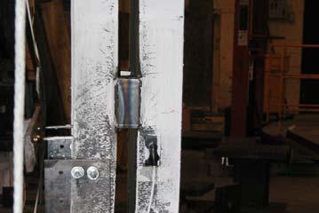
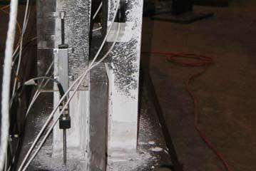
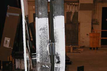

99 (a) Figure 3.11 (a) Lateral-torsional buckling in Specimens C1 at 1.5% story drift; (b) Fracture of the channel leg in Specimen C1 (b) (a) (b) Figure 3.12 Lateral-torsional buckling in Specimens C2 at (a) 1.5% story drift; (b) 3.0% story drift
 Channel")

 Figure 3.")

100 a) Channel Flange Local Buckling b) Channel Fracture Figure 3.13 Local buckling and fracture in Specimen C2 (a) (b) Figure 3.14 Lateral-torsional buckling in Specimens C3 at (a) 1.5% story drift; (b) 3.0% story drift
 Cracking of gusset plate-channel")

 Yielding pattern and")
 Fracture of channel")
101 (a) (b) Figure 3.15 (a) Cracking of gusset plate-channel connection and (b) fracture of channel in Specimen C3 during 3.5% story drift cycle (a) (b) Figure 3.16 Specimen C4: (a) Yielding pattern and local buckling at the second cycle of 3.0% story drift; (b) Fracture of channel during the third cycle to 3.0% story drift
 Yielding pattern and local")
 Fracture of channel during")
 (b) Figure 3.")

102 (a) (b) Figure 3.17 Specimen C5: (a) Yielding pattern and local buckling at the third cycle of 3.0% story drift; (b) Fracture of channel during the fourth cycle to 3.0% story drift (a) (b) Figure 3.18 Specimen C6: (a) Yielding pattern and local buckling at the fourth cycle of 3.0% story drift; (b) Fracture of channel during the second cycle to 3.5% story drift


 1")


")


")


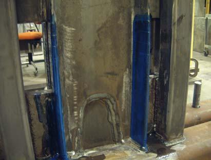
103 (3" 3" 1 4 ") 1 9 " 2 1 (10" 24" 1 4 ") " Figure 3.19 (a) Detail of Specimen C7 Figure 3.19 (b) Detail of the carbon woven mesh wrapping on Specimen C7 (unit: inches)
 Yielding pattern and local buckling at the fourth cycle")
 -4.5-4 -3.5-3 -2.5-2 -1.")
 25 0-25 -50-75 -100-6 -5-4 -3-2 -1 0 1 2 3")
104 (a) (b) Figure 3.20 Specimen C7: (a) Yielding pattern and local buckling at the fourth cycle of 3.0% story drift; (b) Fracture of channel during the second cycle to 3.5% story drift Prototype Structure Story Drift (%) Lateral Load (kips) Displacement (in.) Figure 3.21 Lateral load versus story drift response of Specimen C7
PERFORMANCE-BASED PLASTIC DESIGN AND ENERGY-BASED EVALUATION OF SEISMIC RESISTANT RC MOMENT FRAME
 Journal of Marine Science and Technology, Vol., No., pp. - () PERFORMANCE-BASED PLASTIC DESIGN AND ENERGY-BASED EVALUATION OF SEISMIC RESISTANT RC MOMENT FRAME Wen-Cheng Liao and Subhash C. Goel Key words:
FURTHER REFI EME T OF PERFORMA CE-BASED PLASTIC DESIG OF STRUCTURES FOR EARTHQUAKE RESISTA CE
 FURTHER REFI EME T OF PERFORMA CE-BASED PLASTIC DESIG OF STRUCTURES FOR EARTHQUAKE RESISTA CE ABSTRACT : M. Reza Bayat 1, Subhash C. Goel 2, and Shih-Ho Chao 3 1 Graduate Student, University of Texas,
A SEISMIC DESIGN METHOD FOR STEEL CONCENTRIC BRACED FRAMES FOR ENHANCED PERFORMANCE
 4th International Conference on Earthquake Engineering Taipei, Taiwan October 1-13, 6 Paper No. 7 A SEISMIC DESIGN METHOD FOR STEEL CONCENTRIC BRACED FRAMES FOR ENHANCED PERFORMANCE Shih-Ho Chao 1 and
SEISMIC RESPONSE INVESTIGATION OF SPECIAL TRUSS MOMENT FRAME (STMF) SUBASSEMBLIES UNDER QUASI-STATIC LOADING
 SUBASSEMBLIES UNDER QUASI-STATIC LOADING") Abstract SEISMIC RESPONSE INVESTIGATION OF SPECIAL TRUSS MOMENT FRAME (STMF) SUBASSEMBLIES UNDER QUASI-STATIC LOADING Santos Jr. Jordan University of California, Davis University of Nevada, Reno Dr. Sherif
Abstract SEISMIC RESPONSE INVESTIGATION OF SPECIAL TRUSS MOMENT FRAME (STMF) SUBASSEMBLIES UNDER QUASI-STATIC LOADING Santos Jr. Jordan University of California, Davis University of Nevada, Reno Dr. Sherif
International Journal of Advance Engineering and Research Development A REVIEW ON PERFORMANCE BASED PLASTIC DESIGN METHODOLOGY
 Scientific Journal of Impact Factor (SJIF): 5.71 International Journal of Advance Engineering and Research Development Volume 5, Issue 04, April -2018 e-issn (O): 2348-4470 p-issn (P): 2348-6406 A REVIEW
PERFORMANCE-BASED SEISMIC DESIGN OF EBF USING TARGET DRIFT AND YIELD MECHANISM AS PERFORMANCE CRITERIA. Shih-Ho Chao Subhash C.
 March 25 PERFORMANCE-BASED SEISMIC DESIGN OF EBF USING TARGET DRIFT AND YIELD MECHANISM AS PERFORMANCE CRITERIA by Shih-Ho Chao Subhash C. Goel A report on research sponsored by the American Institute
ALUMINIUM SHEAR-LINK FOR SEISMIC ENERGY DISSIPATION
 ALUMINIUM SHEAR-LINK FOR SEISMIC ENERGY DISSIPATION Durgesh C RAI 1 And Benjamin J WALLACE SUMMARY An aluminium shear-link is developed for earthquake resistant structures. It is just an I-shaped beam
Performance-Based Plastic Design Method
 One Week FDP Fundamentals of Structural Dynamics and Application to Earthquake Engineering in Sanjay Ghodawat Group of Institute Performance-Based Plastic Design Method Assistant Professor, Applied Mechanics
Performance-based plastic design of a high rise moment resisting frame with friction dampers
 Earthquake Resistant Engineering Structures X Performance-based plastic design of a high rise moment resisting frame with friction dampers C. S. Patil, V. B. Patil & S. B. Kharmale B. V. B. College of
STRUCTURAL APPLICATIONS OF A REINFORCED CONCRETE BEAM-COLUMN-SLAB CONNECTION MODEL FOR EARTHQUAKE LOADING
 STRUCTURAL APPLICATIONS OF A REINFORCED CONCRETE BEAM-COLUMN-SLAB CONNECTION MODEL FOR EARTHQUAKE LOADING B.B. Canbolat 1 1 Assistant Professor, Dept. of Civil Engineering, Middle East Technical University,
Inelastic Torsional Response of Steel Concentrically Braced Frames
 Inelastic Torsional Response of Steel Concentrically Braced Frames R. Comlek, B. Akbas & O. Umut Gebze Institute of Technology, Gebze-Kocaeli, Turkey J. Shen & N. Sutchiewcharn Illinois Institute of Technology,
INTERNATIONAL JOURNAL OF CIVIL AND STRUCTURAL ENGINEERING Volume 2, No 4, 2012
 INTERNATIONAL JOURNAL OF CIVIL AND STRUCTURAL ENGINEERING Volume 2, No 4, 2012 Copyright 2010 All rights reserved Integrated Publishing services Research article ISSN 0976 4399 Comparison of steel moment
Seismic Performance Evaluation of Eccentrically Braced Frame Using PBPD Method
 Seismic Performance Evaluation of Eccentrically Braced Frame Using PBPD Method Shreya S. Chintawar Asst. Professor, Department of Civil Engineering, Sinhgad College of Engineering, Vadgaon(bk), Pune, India
Comparison between Seismic Behavior of Suspended Zipper Braced Frames and Various EBF Systems
 Comparison between Seismic Behavior of Suspended Zipper Braced Frames and Various EBF Systems A. Niknam 1, A. Sharfaei 2 1- Assistant Professor, Civil Engineering Faculty, University of Science & Technology,
EFFECTS OF COLUMN CAPACITY ON THE SEISMIC BEHAVIOR OF MID-RISE STRONG-COLUMN-WEAK-BEAM MOMENT FRAMES
 EFFECTS OF COLUMN CAPACITY ON THE SEISMIC BEHAVIOR OF MID-RISE STRONG-COLUMN-WEAK-BEAM MOMENT FRAMES Nattapat WONGPAKDEE and Sutat LEELATAVIWAT ABSTRACT The strong-column-weak-beam (SCWB) design philosophy
Evaluation of Response Reduction Factor and Ductility Factor of RC Braced Frame
 12 JOURNAL OF MATERIALS AND ENGINEERING STRUCTURES 2 (215) 12 129 Research Paper Evaluation of Response Reduction Factor and Ductility Factor of RC Braced Frame Kruti Tamboli, J. A. Amin * Department of
EVALUATION OF NONLINEAR STATIC PROCEDURES FOR SEISMIC DESIGN OF BUILDINGS
 EVALUATION OF NONLINEAR STATIC PROCEDURES FOR SEISMIC DESIGN OF BUILDINGS By H.S. Lew 1 and Sashi K. Kunnath Presented at the rd Joint Meeting of the UJNR Panel on Wind and Seismic Effects ABSTRACT This
Effect of Standard No Rules for Moment Resisting Frames on the Elastic and Inelastic Behavior of Dual Steel Systems
 Engineering, Technology & Applied Science Research Vol. 7, No. 6, 2017, 2139-2146 2139 Effect of Standard No. 2800 Rules for Moment Resisting Frames on the Elastic and Inelastic Behavior of Dual Steel
SEISMIC VULNERABILITY ASSESSMENT OF STEEL PIPE SUPPORT STRUCTURES
 10NCEE Tenth U.S. National Conference on Earthquake Engineering Frontiers of Earthquake Engineering July 21-25, 2014 Anchorage, Alaska SEISMIC VULNERABILITY ASSESSMENT OF STEEL PIPE SUPPORT STRUCTURES
A Parametric Study on the Influence of Semi-Rigid Connection Nonlinearity on Steel Special Moment Frames
 A Parametric Study on the Influence of Semi-Rigid Connection Nonlinearity on Steel Special Moment Frames T. Metin 1, A. Sarıtaş 2, 1 RNT Energy LC., Ankara, Turkey, tmetin@rntenerji.com 2 Department of
National Information Service for Earthquake Engineering University of California, Berkeley
 nisee National Information Service for Earthquake Engineering University of California, Berkeley Strength Reduction Factors in Performance-Based Design By Eduardo Miranda National Center for Disaster Prevention
Comparison of Chevron and Suspended Zipper Braced Steel Frames
 9 th International Congress on Advances in Civil Engineering, 27-30 September 2010 Karadeniz Technical University, Trabzon, Turkey Comparison of Chevron and Suspended Zipper Braced Steel Frames A. Y. Ozcelik
Seismic Performance of Residential Buildings with Staggered Walls
 Seismic Performance of Residential Buildings with Staggered Walls Hyungoo Kang and Joonho Lee Graduate Student, Department of Architectural Engineering, Sungkyunkwan University, Suwon, Korea Jinkoo Kim
Pushover Analysis of Reinforced Concrete Structures with Coupled Shear Wall and Moment Frame. *Yungon Kim 1)
") Pushover Analysis of Reinforced Concrete Structures with Coupled Shear Wall and Moment Frame *Yungon Kim 1) 1) R&D Division, Hyundai Engineering and Construction, Yong-in 446-716, Korea 1) yungon.kim@hdec.co.kr
Pushover Analysis of Reinforced Concrete Structures with Coupled Shear Wall and Moment Frame *Yungon Kim 1) 1) R&D Division, Hyundai Engineering and Construction, Yong-in 446-716, Korea 1) yungon.kim@hdec.co.kr
Design Example 2 Reinforced Concrete Wall with Coupling Beams
 Design Example 2 Reinforced Concrete Wall with Coupling Beams OVERVIEW The structure in this design example is a six story office building with reinforced concrete walls as its seismic force resisting
STRUCTURAL DESIGN REQUIREMENTS (SEISMIC PROVISIONS) FOR EXISTING BUILDING CONVERTED TO JOINT LIVING AND WORK QUARTERS
 FOR EXISTING BUILDING CONVERTED TO JOINT LIVING AND WORK QUARTERS") INFORMATION BULLETIN / PUBLIC - BUILDING CODE REFERENCE NO.: LABC Chapter 85 Effective: 01-01-2011 DOCUMENT NO.: P/BC 2011-110 Revised: Previously Issued As: P/BC 2002-110 STRUCTURAL DESIGN REQUIREMENTS
INFORMATION BULLETIN / PUBLIC - BUILDING CODE REFERENCE NO.: LABC Chapter 85 Effective: 01-01-2011 DOCUMENT NO.: P/BC 2011-110 Revised: Previously Issued As: P/BC 2002-110 STRUCTURAL DESIGN REQUIREMENTS
EVALUATION OF SEISMIC PERFORMANCE FACTORS FOR CHEVRON BUCKLING RESTRAINED BRACED FRAMES
 EALUATION OF SEISMIC PERFORMANCE FACTORS FOR CHERON BUCKLING RESTRAINED BRACED FRAMES M.B. Bozkurt 1, Y.O. Özkılıç 2 and C. Topkaya 3 1 Res. Assist. Dr., Civil Eng. Department, Manisa Celal Bayar University,
NON-LINEAR STATIC PUSHOVER ANALYSIS FOR MULTI-STORED BUILDING BY USING ETABS
 NON-LINEAR STATIC PUSHOVER ANALYSIS FOR MULTI-STORED BUILDING BY USING ETABS Polupalli Victor Paul 1, K Sampath Kumar 2 1 PG Student, Dept of Civil Engineering, Nova College of Engineering & Technology,
MODELLING OF SHEAR WALLS FOR NON-LINEAR AND PUSH OVER ANALYSIS OF TALL BUILDINGS
 MODELLING OF SHEAR WALLS FOR NON-LINEAR AND PUSH OVER ANALYSIS OF TALL BUILDINGS Naveed Anwar 1, Thaung Htut Aung 2 ABSTRACT: The Performance Based Analysis and design of buildings and structures, especially
Engr. Thaung Htut Aung M. Eng. Asian Institute of Technology Deputy Project Director, AIT Consulting
 Engr. Thaung Htut Aung M. Eng. Asian Institute of Technology Deputy Project Director, AIT Consulting Selection of Structural systems Load paths Materials Approximate sizing of members Primary mechanisms
MODIFIED STRUCTURAL LAYOUTS FOR STAGGERED TRUSS FRAMING SYSTEMS USED IN SEISMICALLY ACTIVE AREAS
 10NCEE Tenth U.S. National Conference on Earthquake Engineering Frontiers of Earthquake Engineering July 21-25, 2014 Anchorage, Alaska MODIFIED STRUCTURAL LAYOUTS FOR STAGGERED TRUSS FRAMING SYSTEMS USED
Performance-Based Plastic Design (PBPD) of High-Rise Buckling-Restrained Braced Frames
 of High-Rise Buckling-Restrained Braced Frames") Performance-Based Plastic Design (PBPD) of High-Rise Buckling-Restrained Braced Frames D. R. Sahoo Indian Institute of Technology Delhi, New Delhi, India S.-H. Chao The University of Texas at Arlington,
Performance-Based Plastic Design (PBPD) of High-Rise Buckling-Restrained Braced Frames D. R. Sahoo Indian Institute of Technology Delhi, New Delhi, India S.-H. Chao The University of Texas at Arlington,
COMPARISON OF LOW-RISE STEEL CHEVRON AND SUSPENDED ZIPPER BRACED FRAMES
 Eighth International Conference on ADVANCES IN STEEL STRUCTURES Lisbon, Portugal, July -4, 15 COMPARISON OF LOW-RISE STEEL CHEVRON AND SUSPENDED ZIPPER BRACED FRAMES Yigit Ozcelik*, Afsin Saritas** and
INFLUENCE OF DIFFERENT TYPES OF FULLY RESTRAINED CONNECTIONS ON THE RESPONSE OF SMRF STRUCTURES
 INFLUENCE OF DIFFERENT TYPES OF FULLY RESTRAINED CONNECTIONS ON THE RESPONSE OF SMRF STRUCTURES Akshay GUPTA And Helmut KRAWINKLER SUMMARY The behavior, response, and performance of code-compliant designs
A Comparison of Basic Pushover Methods
 International Refereed Journal of Engineering and Science (IRJES) ISSN (Online) 2319-183X, (Print) 2319-1821 Volume 2, Issue 5(May 2013), PP. 14-19 A Comparison of Basic Pushover Methods N.K. Manjula 1,
DESIGN ASPECTS AFFECTING THE SEISMIC BEHAVIOUR OF STEEL MRF BUILDINGS: ANALYSIS OF THREE CASE STUDIES
 DESIGN ASPECTS AFFECTING THE SEISMIC BEHAVIOUR OF STEEL MRF BUILDINGS: ANALYSIS OF THREE CASE STUDIES E MELE 1, A DE LUCA 2 And L DI SARNO 3 SUMMARY The seismic performance of three partial perimeter and
Seismic design of braced frame gusset plate connections
 Earthquake Resistant Engineering Structures V 105 Seismic design of braced frame gusset plate connections C. W. Roeder, D. E. Lehman, A. Christopolus, I. Gunnarson, S. Johnson & J. H. Yoo Department of
PERFORMANCE-BASED SEISMIC DESIGN OF BRACED-FRAME GUSSET PLATE CONNECTIONS
 PERFORMANCE-BASED SEISMIC DESIGN OF BRACED-FRAME GUSSET PLATE CONNECTIONS C.W. Roeder, U. of Washington, Seattle, WA, USA D.E. Lehman, U. of Washington, Seattle, WA, USA J. H. Yoo, U. of Washington, Seattle,
International Journal of Advance Engineering and Research Development
 International Journal of Advance Engineering and Research Development Scientific Journal of Impact Factor (SJIF): 4.7 Special Issue SIEICON-017,April -017 e-issn : 348-4470 p-issn : 348-6406 Comparison
Seismic assessment of an existing hospital
 International Students Conference of Civil Engineering, ISCCE 2012, 10-11 May 2012, Epoka University, Tirana, Albania Seismic assessment of an existing hospital Egla Luca Department of Civil Engineering,
Index terms Diagrid, Nonlinear Static Analysis, SAP 2000.
 Pushover Analysis of Diagrid Structure Ravi K Revankar, R.G.Talasadar P.G student, Dept of Civil Engineering, BLDEA S V.P Dr P.G Halakatti College of Engineering & Technology Bijapur-586101 Associate Professor,
PUSHOVER ANALYSIS OF A 19 STORY CONCRETE SHEAR WALL BUILDING
 13 th World Conference on Earthquake Engineering Vancouver, B.C., Canada August 1-6, 2004 Paper No. 133 PUSHOVER ANALYSIS OF A 19 STORY CONCRETE SHEAR WALL BUILDING Rahul RANA 1, Limin JIN 2 and Atila
The Effect of Frame Geometry on the Seismic Response of Self-Centering Concentrically- Braced Frames
 International Journal of Civil and Environmental Engineering 6 212 The Effect of Frame Geometry on the Seismic Response of Self-Centering Concentrically- Braced Frames David A. Roke and M. R. Hasan Abstract
APPLICATION OF ENERGY DISSIPATION TECHNOLOGY FOR RETROFITTING STEEL STRUCTURES WITH VULNERABLE PRE- NORTHRIDGE CONNECTIONS
 Proceedings of Seminar on Response Modification Applied Technology Council Abstract APPLICATION OF ENERGY DISSIPATION TECHNOLOGY FOR RETROFITTING STEEL STRUCTURES WITH VULNERABLE PRE- NORTHRIDGE CONNECTIONS
HYBRID MOMENT RESISTING STEEL FRAMES
 HYBRID MOMENT RESISTING STEEL FRAMES Finley A. Charney 1 and Ozgur Atlayan 2 1 Associate Professor, Department of Civil and Environmental Engineering, Virginia Tech, Blacksburg, VA, 2461, USA 2 Graduate
SEISMIC BEHAVIOR OF RCS BEAM-COLUMN-SLAB SUBASSEMBLIES DESIGNED FOLLOWING A CONNECTION DEFORMATION-BASED CAPACITY DESIGN APPROACH
 13 th World Conference on Earthquake Engineering Vancouver, B.C., Canada August 1-6, 2004 Paper No. 300 SEISMIC BEHAVIOR OF RCS BEAM-COLUMN-SLAB SUBASSEMBLIES DESIGNED FOLLOWING A CONNECTION DEFORMATION-BASED
EVALUATION OF RESPONSE REDUCTION FACTOR OF RC FRAMED BUILDINGS BY PUSHOVER ANALYSIS
 EVALUATION OF RESPONSE REDUCTION FACTOR OF RC FRAMED BUILDINGS BY PUSHOVER ANALYSIS 1 VENKATA RAMANA R. L., 2 INGLE R. K. 1 M.Tech. Student, 2 Professor, Department of Applied Mechanics, VNIT, Nagpur,
Inelastic Deformation Demands of Non-Ductile Reinforced Concrete Frames Strengthened with Buckling-Restrained Braces
 Proceedings of the Tenth Pacific Conference on Earthquake Engineering Building an Earthquake-Resilient Pacific 6-8 November 2015, Sydney, Australia Inelastic Deformation Demands of Non-Ductile Reinforced
Concept of Earthquake Resistant Design
 Concept of Earthquake Resistant Design Sudhir K Jain Indian Institute of Technology Gandhinagar November 2012 1 Bhuj Earthquake of 2001 Magnitude 7.7, ~13,805 persons dead Peak ground acceleration ~0.60g
Performance Based Plastic Design of Concentrically Braced Frame attuned with Indian Standard code and its Seismic Performance Evaluation
 168 JOURNAL OF MATERIALS AND ENGINEERING STRUCTURES 2 (2015) 168 179 Research Paper Performance Based Plastic Design of Concentrically Braced Frame attuned with Indian Standard code and its Seismic Performance
Initial cost and seismic vulnerability functions for buildings with energy-dissipating devices
 Safety and Security Engineering 161 Initial cost and seismic vulnerability functions for buildings with energy-dissipating devices J. García-Pérez, M. Zenteno & O. Díaz Instituto de Ingeniería, Mecánica
Inelastic Versus Elastic Displacement-Based Intensity Measures for Seismic Analysis
 IACSIT International Journal of Engineering and Technology, Vol., No., December Inelastic Versus Elastic Displacement-Based Intensity Measures for Seismic Analysis L. Lin and Y. L. Gao, Member, IACSIT
Seismic Evaluation of Infilled RC Structures with Nonlinear Static Analysis Procedures
 Seismic Evaluation of Infilled RC Structures with Nonlinear Static Analysis Procedures M.J. Favvata, M.C. Naoum, C.G. Karayannis Democritus University of Thrace, Greece SUMMARY: Nonlinear static procedures
DISPLACEMENT-BASED SEISMIC ASSESSMENT OF EXISTING NON- DUCTILE STEEL CONCENTRICALLY BRACED FRAMES
 13 th World Conference on Earthquake Engineering Vancouver, B.C., Canada August 1-6, 2004 Paper No. 757 DISPLACEMENT-BASED SEISMIC ASSESSMENT OF EXISTING NON- DUCTILE STEEL CONCENTRICALLY BRACED FRAMES
Modeling of Reinforced Concrete Folded Plate Structures for Seismic Evaluation Swatilekha Guha Bodh
 Modeling of Reinforced Concrete Folded Plate Structures for Seismic Evaluation Swatilekha Guha Bodh Abstract Folded Plates and spatial structures are adopted for construction of large span structures in
SEISMIC CODE DEVELOPMENT FOR STEEL STRUCTURES by Helmut Krawinkler*
 127 SEISMIC CODE DEVELOPMENT FOR STEEL STRUCTURES by Helmut Krawinkler* Presented at the Pacific Structural Steel Conference, Auckland, August 1986 SYNOPSIS This paper discusses revisions proposed by the
N Vamshi Krishna* et al. ISSN: [IJESAT] [International Journal of Engineering Science & Advanced Technology] Volume-3, Issue-1,
![N Vamshi Krishna* et al. ISSN: [IJESAT] [International Journal of Engineering Science & Advanced Technology] Volume-3, Issue-1,](/thumbs/94/122261577.jpg "N Vamshi Krishna* et al. ISSN: [IJESAT] [International Journal of Engineering Science & Advanced Technology] Volume-3, Issue-1,") Design of steel plate shear walls considering inelastic drift demand N Vamsi Krishna Structural Engineer, GE Consultancy, Hyderabad, TS, India narayanadavamshi@gmail.com Abstract The unstiffened steel
Design of steel plate shear walls considering inelastic drift demand N Vamsi Krishna Structural Engineer, GE Consultancy, Hyderabad, TS, India narayanadavamshi@gmail.com Abstract The unstiffened steel
REHABILITATION OF RC BUILDINGS USING STRUCTURAL WALLS
 REHABILITATION OF RC BUILDINGS USING STRUCTURAL WALLS Ahmed GHOBARAH 1 And Maged YOUSSEF 2 SUMMARY A developed macroscopic model is applied to the analysis of an example structure to demonstrate the use
SEISMIC DESIGN AND ANALYSIS OF HYBRID MASONRY WITH FUSE CONNECTORS ROBERT ASSELIN THESIS
 SEISMIC DESIGN AND ANALYSIS OF HYBRID MASONRY WITH FUSE CONNECTORS BY ROBERT ASSELIN THESIS Submitted in partial fulfillment of the requirements for the degree of Master of Science in Civil Engineering
SEISMIC EVALUATION OF ECCENTRICALLY BRACED STEEL FRAMES DESIGNED BY PERFORMANCE-BASED PLASTIC DESIGN METHOD
 SEISMIC EVALUATION OF ECCENTRICALLY BRACED STEEL FRAMES DESIGNED BY PERFORMANCE-BASED PLASTIC DESIGN METHOD ABSTRACT : Sachi Furukawa, Subhash C. Goel, and Shih-Ho Chao 3 Formerly Graduate Student, University
NON LINEAR STATIC ANALYSIS OF DUAL RC FRAME STRUCTURE
 NON LINEAR STATIC ANALYSIS OF DUAL RC FRAME STRUCTURE Sauhardra Ojha 1,Arunendra Mishra 2 Mohd Firoj 3,Dr.K.Narayan 4 1,2,3 P.G.student of Civil Engineering department, Institute of Engineering and Technology
Seismic Performance and Design of Linked Column Frame System (LCF)
") Seismic Performance and Design of Linked Column Frame System (LCF) M. Malakoutian & J.W. Berman Department of Civil and Environmental Engineering, University of Washington, Seattle, WA, USA P. Dusicka
Seismic Performance and Design of Linked Column Frame System (LCF) M. Malakoutian & J.W. Berman Department of Civil and Environmental Engineering, University of Washington, Seattle, WA, USA P. Dusicka
Experimental Evaluation of The Seismic Behavior of Steel- Braced RC Frames
 1/7 Paper IFHS-211 Experimental Evaluation of The Seismic Behavior of Steel- Braced RC Frames M. L. Nehdi Currently at Alhosn University, Abu Dhabi, United Arab Emirates M. A. Youssef and H. Ghaffarzadeh
SEISMIC DAMAGE CONTROL WITH PASSIVE ENERGY DEVICES: A CASE STUDY
 SEISMIC DAMAGE CONTROL WITH PASSIVE ENERGY DEVICES: A CASE STUDY by Robert J. McNamara, SE McNamara/Salvia, Inc. Consulting Structural Engineers One International Place Boston, MA 02110 This paper presents
Seismic Evaluation of Steel Moment Resisting Frame Buildings with Different Hysteresis and Stiffness Models
 Seismic Evaluation of Steel Moment Resisting Frame Buildings with Different Hysteresis and Stiffness Models ABSTRACT : Jiwook Shin 1 and Kihak Lee 2* 1 M.S. student, Dept. of Architectural Engineering,
DRIFT AND YIELD MECHANISM BASED SEISMIC DESIGN AND UPGRADING OF STEEL MOMENT FRAMES. Sutat Leelataviwat
 DRIFT AND YIELD MECHANISM BASED SEISMIC DESIGN AND UPGRADING OF STEEL MOMENT FRAMES by Sutat Leelataviwat A dissertation submitted in partial fulfillment of the requirements for the degree of Doctor of
Ductile Design of Steel Structures
 Ductile Design of Steel Structures Michel Bruneau, Ph.D., P.Eng. Chia-Ming Uang, Ph.D. Rafael Sabelli, S.E. Second Edition Mc Grain/ Hill New York Chicago San Francisco Lisbon London Madrid Mexico City
This point intends to acquaint the reader with some of the basic concepts of the earthquake engineer:
 Chapter II. REVIEW OF PREVIOUS RESEARCH II.1. Introduction: The purpose of this chapter is to review first the basic concepts for earthquake engineering. It is not intended to review the basic concepts
An Investigation on Bracing Configuration Effects on Behavior of Diagonally Braced Frames
 An Investigation on Bracing Configuration Effects on Behavior of Diagonally Braced Frames P. Shademan Heidari, H. Kayhani, R. Ahmady Jazany ABSTRACT This study aims at evaluating the effects of different
3. Analysis Procedures
 3. Analysis Procedures 3.1 Scope This chapter sets forth requirements for analysis of buildings using the Systematic Rehabilitation Method. Section 3.2 specifies general analysis requirements for the mathematical
Seismic performance of RC frames with concentric internal steel bracing
 Engineering Structures 29 (2007) 1561 1568 www.elsevier.com/locate/engstruct Seismic performance of RC frames with concentric internal steel bracing M.A. Youssef a,, H. Ghaffarzadeh b, M. Nehdi a a Department
CHAPTER 1 INTRODUCTION 1.1 MOMENT END-PLATE CONNECTIONS
 CHAPTER 1 INTRODUCTION 1.1 MOMENT END-PLATE CONNECTIONS The typical moment end-plate connection shown in Fig. 1-1 consists of a plate that is shop-welded to the end of a beam which is then bolted to the
Masonry infills with window openings and influence on reinforced concrete frame constructions
 Earthquake Resistant Engineering Structures VII 445 Masonry infills with window openings and influence on reinforced concrete frame constructions D. J. Kakaletsis Technological Educational Institution
Academia Arena 2014;6(1) Seismic performance evaluation of steel knee-braced moment frames
 Seismic performance evaluation of steel knee-braced moment frames") Seismic performance evaluation of steel knee-braced moment frames Bahman Farokhi 1, Alireza Bazvand 2 1 Student, ph.d of civil engineering, university of malayer, iran (corresponding Author) Abstract:
Seismic performance evaluation of steel knee-braced moment frames Bahman Farokhi 1, Alireza Bazvand 2 1 Student, ph.d of civil engineering, university of malayer, iran (corresponding Author) Abstract:
Span Length Effect on Seismic Demand on Column Splices in Steel Moment Resisting Frames
 Span Length Effect on Seismic Demand on Column Splices in Steel Moment Resisting Frames B. Akbas Gebze Institute of Technology, Turkey Blank Line 9 pt O. Seker Yildiz Technical University, Turkey Blank
International Journal of Engineering and Techniques - Volume 4 Issue 2, Mar Apr 2018
 RESEARCH ARTICLE Seismic Analysis of Steel Frames Subjected to Braced Connections Matha Prasad Adari* *Assistant Professor, Dept. of Civil Engineering. NSRIT Visakhapatnam, Andhra Pradesh, INDIA. 1.INTRODUCTION
AN EVALUATION OF THE DISPLACEMENT CONTROLLED DESIGN PROCEDURES
 1 AN EVALUATION OF THE DISPLACEMENT CONTROLLED DESIGN PROCEDURES Vladimir SIGMUND 1, Ivica GULJAS And Kresimir HERMAN 3 SUMMARY When yielding occurs in a structure during extreme earthquakes formation
Design check of BRBF system according to Eurocode 8 Use of pushover analysis
 2010 Design check of BRBF system according to Eurocode 8 Use of pushover analysis This report presents a simple computerbased push-over analysis for a steel structure with Buckling Restrained Braced Frame
UPGRADING THE DUCTILITY AND SEISMIC BEHAVIOR FACTOR OF ORDINARY RC FRAMES USING FIBER COMPOSITE SHEETS
 CD04-001 UPGRADING THE DUCTILITY AND SEISMIC BEHAVIOR FACTOR OF ORDINARY RC FRAMES USING FIBER COMPOSITE SHEETS A. Niroomandi 1, A. Maheri 2 1 Seismic Retrofitting Center, Shiraz University, Iran 2 Faculty
Engineering Structures. Performance-based plastic design method for buckling-restrained braced frames
 Engineering Structures 32 (2010) 2950 2958 Contents lists available at ScienceDirect Engineering Structures journal homepage: www.elsevier.com/locate/engstruct Performance-based plastic design method for
ctbuh.org/papers CTBUH Recommendations for the Seismic Design of High-Rise Buildings
 ctbuh.org/papers Title: Author: Subject: CTBUH Recommendations for the Seismic Design of High-Rise Buildings Michael Willford, Council on Tall Buildings and Urban Habitat Structural Engineering Publication
Overview of Presentation. SCBFs are Conceptually Truss Structures
 Ultimate Strength and Inelastic Behavior of Braced Frame Gusset Plate Connections Charles W. Roeder University of Washington Department of Civil and Environmental Engineering Seattle, WA 98195 Structural
INTERNATIONAL JOURNAL OF PURE AND APPLIED RESEARCH IN ENGINEERING AND TECHNOLOGY
 INTERNATIONAL JOURNAL OF PURE AND APPLIED RESEARCH IN ENGINEERING AND TECHNOLOGY A PATH FOR HORIZING YOUR INNOVATIVE WORK SPECIAL ISSUE FOR NATIONAL LEVEL CONFERENCE "SUSTAINABLE TECHNOLOGIES IN CIVIL
Chapter 4 Commentary STRUCTURAL DESIGN CRITERA
 Chapter 4 Commentary STRUCTURAL DESIGN CRITERA 4.1 GENERAL 4.1.2 References. ASCE 7 is referenced for the combination of earthquake loadings with other loads as well as for the computation of other loads;
Modeling of Shear Walls for Nonlinear and Pushover Analysis of Tall Buildings
 Asian Center for Engineering Computations and Software, AIT Asian Institute of Technology, Thailand 14th ASEP International Convention, Philippines, May 2009 Modeling of Shear Walls for Nonlinear and Pushover
Survey and Testing of Pre-1988 Braced Frame Structures From The West Coast of the United States
 Survey and Testing of Pre-1988 Braced Frame Structures From The West Coast of the United States Dan Sloat 1, Charles W. Roeder 2, Dawn E. Lehman 3, and Jeffrey W. Berman 4 1 Graduate Student, Dept. of
Seismic Steel Design 12/9/2012
 Chapter 8 Design of Seismic-Resistant Steel Building Structures: A Brief Overview SEISMIC STEEL DESIGN IN CANADA and the USA Instructor: Dr. Carlos E. Ventura, P.Eng. Department of Civil Engineering The
Seismic Design Principles for RC Structures
 CE 490 Int. to Earthquake Engineering Seismic Design Principles for RC Structures H. Sucuoğlu Introduction Seismic design of structural systems is essentially based on an inherent ductile response under
Modeling for Structural Analysis
 Modeling for Structural Analysis Behavior and Basics Graham H. Powell Professor Emeritus of Structural Engineering University of California at Berkeley Computers and Structures, Inc., Berkeley, California,
Trends in the Displacement-Based Seismic Design of Structures, Comparison of Two Current Methods
 Trends in the Displacement-Based Seismic Design of Structures, Comparison of Two Current Methods H. Castellanos & A. G. Ayala Instituto de Ingeniería, Universidad Nacional Autónoma de México, México SUMMARY:
SEISMIC DESIGN OF STRUCTURE
 SEISMIC DESIGN OF STRUCTURE PART I TERMINOLOGY EXPLANATION Chapter 1 Earthquake Faults Epicenter Focal Depth Focus Focal Distance Epicenter Distance Tectonic Earthquake Volcanic Earthquake Collapse Earthquake
STRENGTH REDUCTION FACTORS FOR MULTI-DEGREE-OF-FREEDOM SYSTEMS
 STRENGTH REDUCTION FACTORS FOR MULTI-DEGREE-OF-FREEDOM SYSTEMS Perla R SANTA-ANA 1 And Eduardo MIRANDA 2 SUMMARY Strength reduction factors of multi-degree-of-freedom (MDOF) structures are investigated.
THE STUDY OF THE OVER STRENGTH FACTOR OF STEEL PLATE SHEAR WALLS BY FINITE ELEMENT METHOD
 THE STUDY OF THE OVER STRENGTH FACTOR OF STEEL PLATE SHEAR WALLS BY FINITE ELEMENT METHOD Mahin Abdollahzadeh 1, *Arman Kabiri 1 and Ramin Amjadi 2 1 Department of Civil Engineering, Islamic Azad University,
Damage-control Seismic Design of Moment-resisting RC Frame Buildings
 Damage-control Seismic Design of Moment-resisting RC Frame Buildings Huanun Jiang* 1, Bo Fu 2 and Linzhi Chen 3 1 Professor, State Key Laboratory of Disaster Reduction in Civil Engineering, Tongi University,
A CASE STUDY OF PERFORMANCE-BASED SEISMIC EVALUATION AND RETROFIT OF AN EXISTING HOSPITAL BUILDING IN CALIFORNIA, U.S.
 A CASE STUDY OF PERFORMANCE-BASED SEISMIC EVALUATION AND RETROFIT OF AN EXISTING HOSPITAL BUILDING IN CALIFORNIA, U.S. W. Huang 1, L.A. Toranzo-Dianderas 1, A.D. Reynolds 1, J.R. Gavan 1, and J.W. Wallace
A COMPARISON BETWEEN THE REQUIREMENTS OF PRESENT AND FORMER ROMANIAN SEISMIC DESIGN CODES, BASED ON THE REQUIRED STRUCTURAL OVERSTRENGTH
 A COMPARISON BETWEEN THE REQUIREMENTS OF PRESENT AND FORMER ROMANIAN SEISMIC DESIGN CODES, BASED ON THE REQUIRED STRUCTURAL OVERSTRENGTH I.-G. Craifaleanu 1 1 Associate Professor, Dept. of Reinforced Concrete
Seismic performance assessment of reinforced concrete buildings using pushover analysis
 IOSR Journal of Mechanical and Civil Engineering (IOSR-JMCE) ISSN: 2278-1684 Volume 5, Issue 1 (Jan. - Feb. 2013), PP 44-49 Seismic performance assessment of reinforced concrete buildings using pushover
Beam-column joint tests with grade 500E reinforcing
 Beam-column joint tests with grade 500E reinforcing L.M. Megget & N.J. Brooke Department of Civil & Environmental Engineering, University of Auckland, New Zealand. R.C. Fenwick Visitor, Department of Civil
4.2 Tier 2 Analysis General Analysis Procedures for LSP & LDP
 4.2 Tier 2 Analysis 4.2.1 General Four analysis procedures are provided in this section: Linear Static Procedure (LSP), Linear Dynamic Procedure (LDP), Special Procedure, and Procedure for Nonstructural
0306 SEISMIC LOADS GENERAL
 0306 SEISMIC LOADS 0306.1 GENERAL Every structure, and portion thereof, including nonstructural components such as architectural, mechanical, and electrical components, shall be designed and constructed