SIMULATION OF DYNAMIC IMPACT OF SELF-CENTERING CONCENTRICALLY- BRACED FRAMES USING LS-DYNA 971. A Thesis. Presented to. In Partial Fulfillment
|
|
|
- Isaac Warren
- 6 years ago
- Views:
Transcription
1 SIMULATION OF DYNAMIC IMPACT OF SELF-CENTERING CONCENTRICALLY- BRACED FRAMES USING LS-DYNA 971 A Thesis Presented to The Graduate Faculty of The University of Akron In Partial Fulfillment of the Requirements for the Degree Master of Science Lucie Blin-Bellomi August, 2012
2 SIMULATION OF DYNAMIC IMPACT OF SELF-CENTERING CONCENTRICALLY- BRACED FRAMES USING LS-DYNA 971 Lucie Blin-Bellomi Thesis Approved: Accepted: Advisor Dr. Wieslaw K. Binienda Department Chair Dr. Wieslaw K. Binienda Committee Co-Chair Dr. David Roke Dean of the College Dr. George K. Haritos Committee Member Dr. Gunjin Yun Dean of the Graduate School Dr. George R. Newkome Date ii
3 ABSTRACT This paper focuses on the finite element simulation of a self-centering concentrically-braced frame (SC-CBF) using the LS-DYNA 971 solver. SC-CBFs have been developed as a damage-free alternative to conventional concentrically braced frame (CBF) systems. Previous experimental pseudo-dynamic hybrid simulation results for SC-CBF systems indicated that the system works as intended; however, these pseudo-dynamic tests were unable to measure the effect of the mass of the SC-CBF structure on the dynamic response. This thesis analyzes the dynamic effect of the mass on a SC-CBF using the LS-DYNA software. A finite element model (FEM) of a buckling restrained braced frame (BRBF) was built to calibrate an LS-DYNA model to experimental results. This study parallels published experimental and finite element analysis results, and validates the finite element analysis method chosen to conduct the SC-CBF impact study. The objective of the thesis is to determine the effect of the mass of the SC-CBF on dynamic response. A comparative study is undertaken with two different FEMs of the SC-CBF system: one including the mass of the steel, and one treating the steel as massless. iii
4 ACKNOWLEDGEMENTS The research presented in this thesis was conducted at the University of Akron, Department of Civil Engineering, in Akron, Ohio. During the study, the chairmanship of the department was held by Dr. Wieslaw K. Binienda. I would like to thank Dr. Binienda, my thesis advisor, for his constant support and guidance throughout this research. Thank you to Dr.Roke, who directed my research study and with whom I learned a lot about earthquake engineering, especially SC-CBFs. I would also like to thank Dr. Gunjin Yun, the final member of this thesis committee, for his time, advice, and input. Great thanks to the other students of Dr.Binienda, Chao Zhang and Zhuopei Hu, who literally taught me how to use LS-DYNA and gave me crucial advice. Thank you so much Chao Zhang for your precious time and availability any time. Finally, special thanks for my parents, who have always been available for me all along this year and who believe in me with every decision that I take. iv
5 TABLE OF CONTENTS Page CHAPTER I. RESEARCH SCOPE Objectives Research tasks Organization of Thesis...2 II. BACKGROUND Earthquake Hazard Structural effects Northridge earthquake Earthquake Engineering Practice Concentrically braced frame systems Modifications to CBF systems Base isolation Buckling Restrained Brace Frames Self-centering concentrically-braced frame systems...15 III. VALIDATION OF FINITE ELEMENT MODEL FOR BRBF Objectives LS-DYNA Program Model Data Original Data Material Properties Frame Geometry Member and connection modeling Brace modeling Restraint and Loading Protocol Finite Element analysis Meshing Simulation errors...34 v
6 3.5 Analysis Results Plastic strain Displacement Conclusions...43 IV. SC-CBF FINITE ELEMENT MODEL DEVELOPMENT Objectives Source Material Model Data Material Properties Frame geometry Loading protocol Ground Motions Source material Modeling...63 V. RESULTS Assumptions and Limitations Analysis Results Santasusana site (5108) Orientation 90 of the Santansusana site ( ) Orientation 360 of the Santasusana site ( ) Arleta site (arl) Orientation 90 of the Arleta site (arl-090) Orientation 360 of the Arleta site (arl-360) Hollywood Storage site (nrpel) Orientation 90 of the Hollywood storage site (nrpel-090) Orientation 360 of the Hollywood storage site (nrpel-360) Conclusions...87 VI. SUMMARY AND CONCLUSIONS Motivation for Research Summary and findings Conclusions Recommendations...90 vi
7 LIST OF TABLES Table Page 3.1 LS-DYNA consistent units Tested model material characteristics Member dimensions for the BRBF model Unbonded brace properties (Black et al. 2002) Displacement curve values SC-CBF finite element model material characteristics SC-CBF member sizes Final I-beams characteristics (efunda.com) Summary of DBE-level ground motion characteristics (Roke 2010) Maximum stress comparison for Maximum stress comparison for Maximum stress comparison for arl Maximum stress comparison for arl Maximum stress comparison for nrpel Maximum stress comparison for nrpel vii
8 LIST OF FIGURES Figure Page 2.1 Epicenters (lovebigisland.com) Collapse of the second and third story onto the first story of the Northridge Meadows apartment in the 1994 Northridge earthquake (Los Angeles Times) CISN Shake map for Northridge Earthquake (earthquakecountry.info) Chevron braces buckling in a 3 story structure (graitec.com) Commonly used configuration of CBFs (graitec.com) Composition of BRB (hamidsoltani.com) Concept of BRB (starseismic.com) Comparison of the behavior for conventional brace and BRB (scialert.net) Hysteretic behavior of self-centering systems (Filiatrault et al. 2004) Schematic of braced frame system: (a) conventional CBF, (b) SC-CBF (based on Gonner 2009) Elements in LS-DYNA (ls-dyna_971_manual_k.pdf) BRBF structure: (a) experimental structure, (b) finite element model, (Field 2003) Material properties Stress and strain curves for each material BRBF finite element model Unbonded brace, steel core and outer tube (Black et al. 2002) Cross section of the five several braces (Black et al. 2002) Fixed nodes at the base of the frame viii
9 3.10 Nodes with z-axis translation restrained at the top of the loading beam Lateral boundary condition at the flange of the frame Nodes used for displacement control Experimental displacement history (Field 2003) Finite element displacement history Plastic strain at the end of the sixth cycle: (a) Field 2003, (b) current result Plastic strain at the end of the tenth cycle: (a) Field 2003, (b) current result Plastic strain at the end of the fourteenth cycle: (a) Field 2003, (b) current result Displacement result from our FE model Displacement result from Field Overall view of the SC-CBF test structure (Gonner, 2009) LS-DYNA final model SC-CBF behavior: (a) at rest, (b) rocking to the left, and (c) rocking to the right (Gonner, 2009) Schematic of the SC-CBF finite element model Negative peak response to the 360 Santasusana ground motion Schematic of the negative peak response: (a) at the starting instant (point 1); (b) at the maximum displacement (point 2); and (c) at the ending instant (point 3) Positive peak response to the 360 Santasusana ground motion Schematic of the positive peak response: (a) at the starting instant (point 1); (b) at the maximum displacement (point 2); and (c) at the ending instant (point 3) SC-CBF nodal displacements Schematic of a SC-CBF test configuration (Gonner, 2009) Displaced shape of SC-CBF test structure (Gonner, 2009) Frame rocking ix
10 4.13 Maximum gap Experimental structure (Roke 2010) Schematic of LS-DYNA boundary conditions South column boundary conditions for negative peak response Compression-only spring force-displacement relationship Spring elements at the base of the north column for negative peak displacement SC-CBF test frame with adjacent gravity columns and basement substructure (Gonner 2009) Mesh of corner gusset plates Mesh of midspan gusset plates Column base gap opening history for the negative peak of the ground motion response Analysis results of the structure with mass subjected to : (a) 0.444s at impact; (b) 0.446s; (c) 0.448s; (d) 0.450s; (e) 0.452s; (f) 0.454s; (g) 0.456s; (h) 0.458s; (i) 0.460s; (j) 0.462s; (k) 0.464s Analysis results of the structure without mass subjected to : (a) 0.444s at impact; (b) 0.446s; (c) 0.448s; (d) 0.450s; (e) 0.452s; (f) 0.454s; (g) 0.456s; (h) 0.458s; (i) 0.460s; (j) 0.462s; (k) 0.464s Column base gap opening history for the negative peak of the ground motion response Peak stress state for at t = 0.516s: (a) structure with mass, (b) structure without mass Column base gap opening history for the negative peak of the arl-090 ground motion response Peak stress state for arl-090 at t = 0.560s: (a) structure with mass, (b) structure without mass Column base gap opening history for the negative peak of the arl-360 ground motion response Peak stress state for arl-360 at t = 0.438s: (a) structure with mass, (b) structure without mass x
11 5.10 Column base gap opening history for the negative peak of the nrpel-90 ground motion response Peak stress state for nrpel-090 at t = 0.532s: (a) structure with mass, (b) structure without mass Column base gap opening history for the negative peak of the nrpel-360 ground motion response Peak stress state for nrpel-360 at t = 0.490s: (a) structure with mass, (b) structure without mass xi
12 CHAPTER I RESEARCH SCOPE 1.1 Objectives The aim of this thesis is to analyze a self-centering concentrically brace frame (SC- CBF) using the nonlinear finite element method (FEM) using an explicit solver in LS- DYNA to determine whether the mass of the frame affects its dynamic response. This research expands on a previous experimental study reported by Roke et al. (2010) and Chancellor et al. (2010), in which the seismic response of a 0.6-scale prototype SC-CBF system was determined. Due to the pseudo-dynamic testing methods used, the mass of the frame was not included in this previous analysis. Therefore, this research seeks to analytically determine if the mass of the SC-CBF affects its seismic response. 1.2 Research tasks The specific tasks necessary to achieve the research objective are the following: 1. To validate the finite element analysis of a buckling-restrained braced frame (BRBF) system with LS-DYNA; 1
13 2. To perform nonlinear dynamic analyses on the SC-CBF of the previous research to model the experimental response; 3. To study the results of the dynamic analyses to determine the effect of the mass of the SC-CBF. 1.3 Organization of Thesis The remaining chapters of this thesis are organized as follows: Chapter 2 discusses current earthquake engineering practice. Chapter 3 describes the validation of the finite element method used for this thesis, using a finite element model of a BRBF. Chapter 4 discusses the finite element model of the SC-CBF, and the ground motions records used for the analytical study. Chapter 5 discusses the nonlinear numerical dynamic finite element analysis results for the SC-CBF system. Chapter 6 summarizes the research program and offers conclusions and recommendations for future research. 2

14 CHAPTER II BACKGROUND Of the many sources of external lateral load that must be considered in the design of civil engineering structures, one of the most important in terms of its potential for disastrous consequences is earthquake. The degree of importance of earthquake loading is related to regional seismicity, which is highly variable. Figure 2.1 shows the locations of earthquake epicenters between , indicating the global distribution of seismicity. Figure 2.1 Epicenters (lovebigisland.com) 3
15 2.1 Earthquake Hazard Earthquakes are one of the most powerful natural forces which regularly cause deaths and material damages around the world (see Figure 2.1). Unlike other kinds of damaging natural events such as hurricanes and tornadoes, earthquakes can hit at any time, and no early warning system has been developed Structural effects This section discusses the effects of earthquakes on buildings. The waves that create motion at the ground surface emanate from the line of fault rupture, and so approach the building from a particular direction. The nature of the waves and their interactions is such that actual movement at the ground surface is random. The ground motion is predominantly horizontal, often with some directional emphasis, and may have a considerable vertical component. Structural codes (e.g. ASCE 2010) base seismic design requirements on the relative importance of the structure, which is determined based in its occupancy and use. Important structures such as hospitals must sustain very little damage and should be designed for higher lateral forces than less important structures. Thus, it is reasonable to expect an important structure to maintain elastic behavior during a minor earthquake (i.e. the load-carrying members of the structure would not be damaged). However, nonstructural components may sustain repairable damage. During moderate earthquakes, the load-carrying members may sustain repairable damage, while non-structural components may even require replacement after the earthquake. During a severe earthquake, the load- 4

16 carrying members may sustain severe damage, but the structure should not collapse. At such times, plastic behavior of the building is accepted on the premise that the peak forces produced are of short duration and, consequently, can be more readily absorbed by the movement of the structure than a sustained static load can. Therefore, ductile behavior of the building must be ensured. Essentially, structural and nonstructural damage are acceptable outcomes, but the loss of life lust be prevented Northridge earthquake The Northridge earthquake was one of the worst natural disasters in U.S history. It occurred the January 17, 1994, at 4:40 am, at approximately 20 miles northwest of downtown Los Angeles (Los Angeles Times). The magnitude was 6.7 on the Richter scale and the earthquake caused 57 deaths, and more than 1500 serious injuries. Figure 2.2 Collapse of the second and third story onto the first story of the Northridge Meadows apartment in the 1994 Northridge earthquake (Los Angeles Times) 5

. Figure 2.3 CISN Shake map for Northridge Earthquake (earthquakecountry.")
17 This earthquake was significant due to its relatively high magnitude and the great destruction it caused in the San Fernando Valley. The buildings in the San Fernando Valley had been engineered for earthquake resistance after the 1971 Sylmar earthquake (Richter magnitude 6.6). Despite the earthquake resistance of buildings in the Valley, the Northridge earthquake caused significant damage and led to a complete reassessment of the design code (California s Uniform Building Code). Figure 2.3 CISN Shake map for Northridge Earthquake (earthquakecountry.info) 6
18 As this earthquake is particularly interesting from an engineering point of view, the ground motions used in this study are from the 1994 Northridge earthquake. 2.2 Earthquake Engineering Practice The main objective of earthquake engineering is to save lives. A properly engineered structure does not necessarily have to be extremely strong or expensive: instead, it must be properly designed to withstand the seismic effect while sustaining an acceptable level of damage. Conventional structural systems are designed to yield; this damage helps to dissipate energy, maintaining life safety at the cost of the structure. In this study, concentrically braced frame systems will be used to represent the conventional structural design practice Concentrically braced frame systems Concentrically braced frames (CBFs) are seismic-resistant steel frames systems that essentially use vertical trusses to resist sideways forces on buildings. CBFs consist of vertical columns, horizontal beams, and diagonal braces. The design objective for CBFs is to dissipate energy through yielding in the tension braces, preventing yielding or buckling of the beams or columns. The compression braces are intended to buckle. The expected global mechanism is shown in Figure
19 Figure 2.4 Chevron braces buckling in a 3 story structure (graitec.com) When the compression brace buckles, the tension brace force doubles (before buckling, 50% of the lateral force F is resisted by the tension brace and 50% by the compression brace). The vertical component of the tension brace axial force becomes a point load on the beam, pulling the beam down and possibly leading to hinging and buckling of the frame column. CBF design requirements were initially developed in the early 1990s (Roeder 2008), and their evolution continues today. Current AISC seismic design provisions (2005) for CBF systems have several aims. First, the system should have adequate lateral force resistance. Secondly, for extreme earthquakes, the designer must limit the local and global slenderness of the brace members to provide adequate post-buckling inelastic deformation capacity of the braces. Furthermore, the gusset plate connections used to join the braces to other frame members should permit the end rotation of the brace needed for brace buckling, while developing tensile and compressive resistance greater than the maximum expected capacities of the brace. Finally, the primary yielding and buckling must occur in the braces rather than in the beams or columns. 8
20 For small, frequent earthquakes, the structure is designed to remain elastic and provide adequate strength and stiffness to assure serviceability during and after the earthquake. For large, infrequent seismic events, significant inelastic deformation of the structure is required. In the form of tensile yielding and post-buckling inelastic deformation of the braces. This inelastic behavior is extremely important to the overall seismic performance of the system, but leads to negative effects such as residual drift (permanent lateral offset of the building after an earthquake). The quality of the seismic response of CBFs is determined by the performance of the braces. Thus, the braces must fail before any other component of the frame does. There are several common configuration of CBFs, as shown in Figure 2.5: diagonal bracing, in which diagonals connect the joints in adjacent levels (Figure 2.5 (a) ); chevron bracing (subdivided into inverted V bracing and V bracing), in which a pair of braces terminate at a single point within the clear beam span (inverted V bracing is shown in Figure 2.5 (b) and V bracing is shown in Figure 2.5 (c)); X bracing or cross bracing, in which a pair of diagonal braces cross near mid-length of the bracing-members (Figure 2.5d); K bracing, in which a pair of braces located on one side of a column terminate at a single point within the clear column height (Figure 2.5 (e)). The CBF configuration used in this study is chevron braced using inverted V bracing. 9
21 Figure 2.5 Commonly used configuration of CBFs (graitec.com) A CBF is a practical and economical structural system for resisting lateral forces. The braces represent structural fuses and yield in tension. This yielding dissipates energy, helping to reduce the peak dynamic response. However, buckling in compression may lead to a sudden loss of stiffness and progressive degrading behavior which limits the amount of energy dissipation. Furthermore, CBF systems typically have low drift capacity prior to structural damage caused by yielding and buckling, and are therefore often subject to residual drift after earthquakes. Recent research suggests that advancement in the design of CBF is needed. The CBFs do not behave as trusses, as had previously been assumed. The brace and gusset plate connection was design as if the brace was under pure axial load. The welded connection resistance between the gusset plate and the structural members must be strong enough to resist the maximum capacity of the brace in tension and compression. Moreover, the connections must also permit end rotation to accommodate brace buckling. 10
22 The large gusset plate connection required by these criteria creates a stiff, momentresisting connection rather than a pinned connection. This flexural stiffness induces large bending moments in the braces, beams, and columns. These moments effectively increase the resistance of the frame over that expected from the frame analyzed as a pure truss, but also introduce unexpected yield and failure modes on the CBF and complicate the current understanding of braced frame behavior. Furthermore, multi-story CBF systems require special consideration. Design provisions require braces to be used in balanced pairs to assure that the structure is not significantly weaker in one direction than the other at all deformation levels. However, there is an additional consequence of this behavior. Once buckling has occurred in a single story, the inelastic deformation typically concentrates into that story. This leads to an uncertainty about the ability of CBF systems to distribute yielding over the height of the structure. CBFs are very economical, but more research is needed to improve the understanding of their seismic response and to develop design procedures that will result in optimal seismic performance. Several modifications have been studied that can improve the seismic performance of CBF systems Modifications to CBF systems Base isolation One of the simplest methods to improve CBF seismic response is base isolation. The basic concept is to elongate the structural period to push its response into the 11
23 displacement-controlled region of the response spectrum (Kelly 2001). Thus, base isolation provides flexible elements between the superstructure and the foundation. The isolation bearings are not very stiff in the horizontal direction, so they reduce the fundamental frequency (increasing the period) of vibration of the building. Deformations concentrate in these elements and the superstructure moves essentially as a rigid body, reducing the deformation demands of the structural members Buckling Restrained Brace Frames Another significant improvement of the traditional CBFs structures is based on the ductility capacity of the braces. The limited drift capacity of the CBF can be overcome if the brace can yield during both tension and compression without buckling. To achieve this result, buckling-restrained braced frames (BRBFs) have been developed (Baghbanijavid et al. 2010). A BRBF is a special class of CBF that precludes brace buckling. A buckling-restrained brace (BRB) is composed of a steel core encased in a steel tube, which is filled by a concrete matrix. The steel core carries the axial force and the concrete matrix prevents the brace from buckling. Figure 2.6 shows the composition of this system, and Figure 2.7 shows a schematic of the BRB concept. 12
24 Figure 2.6 Composition of BRB (hamidsoltani.com) Figure 2.7 Concept of BRB (starseismic.com) 13
25 This lack of compression buckling leads to symmetric hysteretic behavior for the BRBF. Unlike the braces of a conventional CBF, the BRBs do not buckle, even under large compression forces. Figure 2.8 shows a comparison of the hysteretic behavior of a BRB and a conventional brace. BRBs have a higher energy dissipation capacity than conventional braces, due to the ability of BRBs to yield both in tension and in compression. Figure 2.8 Comparison of the behavior for conventional brace and BRB (scialert.net) Research done on BRBF structure by Baghbanijavid et al. (2010) and Fahnestock et al. (2007a, 2007b) concluded that although BRBFs have significant ductility capacities, they often exhibit large residual drifts like conventional CBFs. These large residual drifts may present significant challenges when seeking to return buildings to service after a major seismic event. 14
26 Self-centering concentrically-braced frame systems Figure 2.9 Hysteretic behavior of self-centering systems (Filiatrault et al. 2004) Self-centering concentrically-braced frame systems (SC-CBFs) have been developed with the goal of providing adequate nonlinear drift capacity without significant damage or residual drift under the design basis earthquake (Roke et al. 2010). The term selfcentering comes from the fact that the system is intended to withstand an earthquake without significant residual lateral drift. The difference between BRBFs and SC-CBFs arises from the methods used to increase the ductility of the braced frame. BRBFs increase the ductility of the brace members, while SC-CBFs soften the global lateral force-lateral drift response by permitting the frame columns to uplift at the base. 15
27 Figure 2.10 Schematic of braced frame system: (a) conventional CBF, (b) SC-CBF (based on Gonner 2009) This softening helps to limit the force demands in the braces, thereby maintaining linear elastic member response. Therefore, the structure can withstand large later drift demands without yielding or buckling the brace members. Vertically oriented posttensioning bars (PT) resist the column uplift and provide a restoring force to self-center the system (i.e., return it to its original position). SC-CBFs maintain the advantages of conventional CBFs (economy and stiffness) while sustaining less damage under seismic loading. However, SC-CBF systems are a relatively new structural engineering development. Analytical and experimental research is still needed to fully understand the system behavior. The purpose of the research is to describe the behavior of the system at the place where impact occurs at the column bases when the gap closes, and examine the effect of the mass of the SC-CBF on its response. 16
28 CHAPTER III VALIDATION OF FINITE ELEMENT MODEL FOR BRBF To validate the finite element analysis (FEA) methods used for this thesis, a preliminary validation model has been developed. This preliminary model, a one-story buckling-restrained braced frame (BRBF), is simpler and smaller than the model used in the model used for the self-centering concentrically braced frame system. The FEA results from the preliminary model will be compared against published experimental and analytical results to validate the FEA methods used in this thesis. 3.1 Objectives The purpose of this research is to study the seismic response of a self-centering concentrically braced system. However, to ensure the validity of the results of the FEA, it is first necessary to compare FEA results with existing data. Therefore, a simple preliminary finite element model of a one-story BRBF was created. This preliminary model is based on experimental and analytical results presented by Field (2003). 17
29 3.2 LS-DYNA Program The commercial transient dynamic finite element software LS-DYNA (Livermore Software Technology Corporation Las Positas Road, Livermore, CA Version LS-DYNA_971 (2011)) is used to conduct the FEA simulations used in this research. This software is capable of simulating complex real world problems, including problems related to the automobile, aerospace, construction, military, manufactory and bioengineering industries. The code s origins lie in highly nonlinear, transient dynamic finite element analysis using explicit time integration. LS-DYNA is highly reliable in fields such as crush, shock, failing shock and plastic forming analysis, or penetration, crack and fracture analysis. As the current research focuses on impact during dynamic response, this software is ideal for the analysis. During model development, several choices are made. Two of the most important are the element type and the mesh density. An element can be a thin rod-like structure (1D rod element), a thin flat structure (2D continuum or shell) a thin 3D structure (shell element) or a massive 3D structure (thick shell or 3D continuum element). Figure 3.1 shows several different element types that are available in LS-DYNA. 18
30 Figure 3.1 Elements in LS-DYNA (ls-dyna_971_manual_k.pdf) Mesh density is the number and the shape of element for a specific area of the model. In order to model a structure efficiently and accurately, it is important that the correct types of elements are used and that the mesh is dense enough to accurately represent the strain distribution in the structure. Economic elements and coarse meshes are easy to generate and run, however, they do not always give the desired results. Another important factor in a finite element model is the unit system. Several systems of units are available in the LS-DYNA software (LS-DYNA keyword user s manual volume I); these unit systems are shown in Table 3.1. Option (a) was selected for this research. 19
31 Table 3.1 LS-DYNA consistent units Option a Option b Option c Mass tonne gram lbf-s²/in Length millimeter millimeter inch Time second millisecond second Force Newton Newton lbf Stress MPa MPa psi Energy N-mm N-mm lbf-in Density (tonne/mm 3 ) Young's (MPa) Gravity (mm/s²) Option a 7.83E E E Model Data Original Data The source for this validation study is a one-story BRBF that was physically tested as part of the design validation for the new Stanley Hall building on the University of California Berkeley Campus (Field 2003). This example illustrates the convenience of the LS-DYNA software for structural applications, transferring this technology to the built environment. 20
 experimental structure, (b) finite element model, (Field 2003) Several unbonded braced frames (chevron or single diagonal) were tested both physically and by a finite element")
32 Figure 3.2 BRBF structure: (a) experimental structure, (b) finite element model, (Field 2003) Several unbonded braced frames (chevron or single diagonal) were tested both physically and by a finite element simulation (Field 2003). The finite element simulations were conducted using the characteristics of the physical structure: geometry, material, restraint and loading protocol. Then, two results are presented from the analyses: plastic strain distribution and force/displacement response. The results indicate that the finite element model accurately portrays the experimental structure. Though the finite element simulation predicts slightly higher values of displacement and horizontal reaction, there is good correlation between analysis and test. 21
33 3.3.2 Material Properties Table 3.2 summarizes the material properties of the preliminary validation finite element model. Figure 3.3 shows the Young s modulus, yield strength, and tangent modulus for the W21x94 flange. Gravity is applied to the model using the Gravity Part option from the Load function. Element Table 3.2 Tested model material characteristics Mass Young's Poisson Type density modulus (tonne/m 3 ratio ) (MPa) Yield strength (MPa) Tangent modulus (MPa) Column W14 x Beam W21 x Loading beam Loading brace W10 x x x Plate steel Varies Unbonded brace (core plate)
34 Tangent modulus Young modulus Yield point Figure 3.3 Material properties The material properties were verified analytically to ensure that the behavior was modeled properly. The resulting stress/strain curves are shown in Figure
35 Figure 3.4 Stress and strain curves for each material Frame Geometry Field (2003) was vague in describing the exact geometry of the frame. The design of the finite element model in this validation study has been carried out as precisely as possible; however, it is important to note that the approximations that were necessary may cause slight differences between the original results and those from this study. This first model is a simple one story frame with chevron bracing. It is composed of steel I-beams: two columns, two braces, one beam, two loading braces and one loading beam. The frame is 6100 mm wide and 3600 mm high. 24
, the depth (d), web thickness (t w ), flange width (b f ), and flange thickness")
36 Loading beam Loading braces Beam Columns Figure 3.5 BRBF finite element model Member and connection modeling The I-beams are standard rolled sections. Table 3.3 indicates the dimensions of the members; the tabulated values are the cross-sectional area (A), the depth (d), web thickness (t w ), flange width (b f ), and flange thickness (t f ). 25
37 Table 3.3 Member dimensions for the BRBF model in x lbf/ft area tf tw Ixx Zxx kxx d (in) bf (in) (in²) (in) (in) (in 4 ) (in 3 Iyy(in 4 Zyy kyy ) ) (in) (in 3 ) (in) W21 x W14 x W10 x After generation of the model, all the connections are fully merged together Brace modeling This preliminary model uses a buckling-restrained brace called the unbonded brace, which is manufactured by Nippon Steel Corporation. An unbonded brace is a type of buckling restrained brace. The unbonded brace behavior refers to the ability of the steel core to contract and elongate freely within the steel-concrete tube assembly. Figure 3.7 shows a schematic of an unbonded brace. 26
38 Figure 3.7 Unbonded brace, steel core and outer tube (Black et al. 2002) Several braces configuration are used in the earthquake design building. In order to match the paper data the most, the 99-2 flat plate which has a 19 x 204 mm core is chosen (Figure 3.8). 27
39 Figure 3.8 Cross section of the five several braces (Black et al. 2002) Thus, we can get the dimensions in detail from the paper Component Testing, stability Analysis and Characterization of Buckling-Restrained Unbonded Braces TM. This research was carrying out at UC Berkeley. Black and al. (2002) tested five bucklingrestrained braces with various configurations. The unbonded braces tested are representative of the braces designed for use in two major building projects in Northern California. The test results established that the unbonded braces tested deliver stable and repeatable behavior. 28

40 Table 3.4 Unbonded brace properties (Black et al. 2002) Restraint and Loading Protocol frame. The structure is restrained by boundary conditions at the bottom and at the top of the The column bases are fully fixed; translations in the x, y, z and directions and rotation about the x, y, and z axes were restrained. Figure 3.11 shows the implementation of these restraints. Fixed nodes Figure 3.9 Fixed nodes at the base of the frame 29
. Figures 3.12 and 3.")

41 At the top of the loading beam, vertical (z-axis) translation and rotation about the z- axis are restrained in order to simulate the top roller connections used in the experimental study (Field 2003). Figures 3.12 and 3.13 indicate the nodes at which these boundary conditions were applied. Vertical boundary condition Figure 3.10 Nodes with z-axis translation restrained at the top of the loading beam Lateral restrain Figure 3.11 Lateral boundary condition at the flange of the frame 30

42 Load is applied on a node set at the left end of the loading beam, as indicated in Figure This node set has rigid material characteristics to simulate the actuator position. Therefore, displacement can be input into the model as support displacement. Rigid part on which displacement is applying Figure 3.12 Nodes used for displacement control The loading protocol follows code recommendations for buckling-restrained braced frames (BSSC 2003). The loading protocol is as follows: - 6 cycles of loading at the deformation Δ b = Δ by - 4 cycles of loading at the deformation Δ b = 0.5Δ by - 4 cycles of loading at the deformation Δ b = Δ bm - 2 cycles of loading at the deformation Δ b =1.5Δ bm In the loading protocol, Δ b is the deformation quantity used to control the loading of the test specimen (total brace axial deformation for the brace test specimen) Δ bm is the value of Δ b, corresponding to the design story drift and Δ by is the value of Δ b, at first significant yielding of the test specimen. The loading protocol used in the 31
43 experimental study (Field 2003) is shown graphically in Figure The displacement values used in this preliminary validation study are tabulated in Table 3.5 and shown graphically in Figure Figure 3.14 Experimental displacement history (Field 2003) 32
44 Table 3.5 Displacement curve values displacement displacement time (s) time (s) (mm) (mm) Figure 3.15 Finite element displacement history 33
45 3.4 Finite Element analysis The entire model uses fully integrated type 16 shell elements. Each element is 30mm x 30mm. Using smaller element would increase the computation time, and the accuracy of this preliminary model is sufficient with this element size Meshing The mesh of this first model is straightforward. The I-beams and gusset plate connections were modeled first. Additional elements like stiffeners and slotted plates were neglected in this preliminary model. Thus, the gusset plates are created as simple surfaces and are meshed accordingly Simulation errors In the case of an LS-DYNA dynamic analysis, several analysis parameters must be taken into consideration. For instance, the chosen time step has an influence on the results of the simulation. The scale factor for the computed time step is taken as 0.9 by default but can be set to 0.6 if high explosives are simulated. The load rate also influences the analysis results. By definition, the load rate is the speed at which load is presented to a component. Here, as the time of the simulation in the original study was not defined, the load curve was applied over a duration of 300s with a time step of 0.9s. This choice allows the load rate to be decreased to improve the correlation of the analysis results. 34
46 3.5 Analysis Results The purpose of this finite element analysis is to compare and validate the force and displacement response of the frame from a displacement input. Moreover, an analysis of the plastic strain response is carried out in order to match the results of the paper Plastic strain To compare the results of this preliminary model to the published results (Field 2003), plastic strain was determined at three times in the analysis: (1) after the sixth cycle (following six cycles to Δ by ); (2) after the tenth cycle (following two cycles to 0.5 Δ bm ); and (3) after the fourteenth cycle (following four cycles to 1.0Δ bm ). These three times are shown in Figure The results of the preliminary finite element model developed for this thesis compare well with those from the published study (Field 2003). The results from Field 2003 and the results from our research are compared in Figures 3.16 (a),(b), 3.17 (a), (b), and 3.18 (a), (b). 35
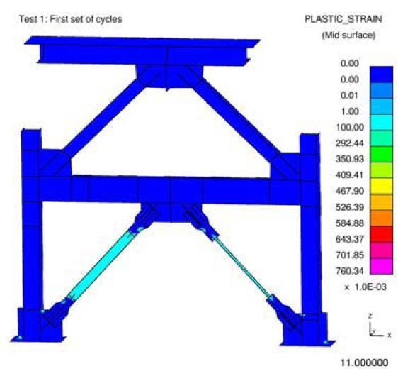
47 (a) 36
48 (b) Figure 3.16 Plastic strain at the end of the sixth cycle: (a) Field 2003, (b) current result 37
49 (a) 38

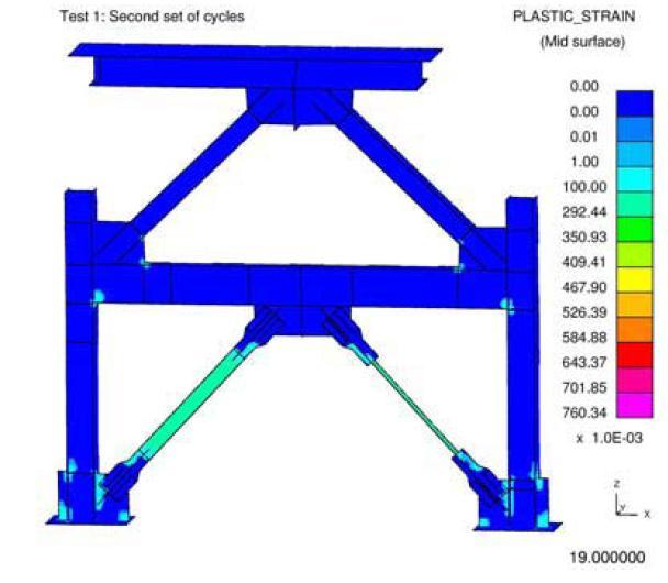
50 (b) Figure 3.17 Plastic strain at the end of the tenth cycle: (a) Field 2003, (b) current result 39
51 (a) 40
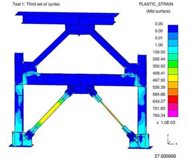
52 (b) Figure 3.18 Plastic strain at the end of the fourteenth cycle: (a) Field 2003, (b) current result Displacement The time interval between outputs is taken as 8.33s to get the same point that the input displacement curve. This option is chosen in the Database Binary D3Plot. We take the x-displacement at the right side of the frame to get the result from the actuator displacement. More precisely, we plot the displacement at node

53 Figure 3.19 Displacement result from our FE model Figure 3.20 Displacement result from Field
54 The plastic strain behavior and displacement curve as well are matching with the results of the Ove & Arup Partners research (Field, 2003). The slight difference between our result and the paper come from the design of the frame. Indeed, given that the dimensions and stiffeners were not clearly detailed, we decided to carry out the study approximating their model. Thus, in Figure 3.18 and 3.19, there is unexpected plastic strain at some locations which are the connections between the beams. These locations are the places where the stiffeners were set up in the real model. Again, the displacement curve show smaller peak than the paper curve. It is due to the energy dissipation from the connections. The stiffeners give strength to the model and prevent this dissipation. 3.6 Conclusions This frame is validated by the paper used. Our LS-DYNA analysis shows the same results as the test of the paper. Thus this validated analysis can be used to design and test other similar structures. So we can use this technique to study the final model of this project. We will detail it in the next chapter and analyze the result that we get. 43
55 CHAPTER IV SC-CBF FINITE ELEMENT MODEL DEVELOPMENT This chapter focuses on the finite element model used for this research on SC-CBF systems. Geometrically, this final model will be similar to the preliminary validation model. Similar material properties and element types were used to develop and run the final model. Therefore, the results are expected to be an accurate representation of SC- CBF seismic response. 4.1 Objectives The purpose of this finite element analysis is to simulate and study the behavior of an SC-CBF frame under several earthquake ground motions. After building the final model, the structure will be subjected to displacement time histories to determine its behavior and the effect of its mass. As with the validation model, this study is based on existing experimental results reported by Roke et al. (2010) and Chancellor et al. (2010). The design and details of the SC-CBF are reported by Gonner (2009). The final purpose of this current study is to analyze the effect of the mass of an SC-CBF by finite element method. Thus, LS-DYNA analysis is essential to study dynamic effects and can lead to a more detailed result. 44
56 4.2 Source Material This chapter describes the design and testing of the final SC-CBF finite element model used for this thesis. Given that the first model has been validated, it can be used to build the final model. The validation model (as described in Chapter III) was a one-story frame with unbonded braces. The final model is a four story SC-CBF with inverted-v chevron bracing (as described in Chapter II). First, the details of the experimental SC-CBF (Gonner 2009) are described, and then the finite element used in this study is described. 45
57 Figure 4.1 Overall view of the SC-CBF test structure (Gonner, 2009) Figure 4.1 shows an overall elevation of the SC-CBF test structure. As in the validation model discussed in Chapter III, the frame consists of columns, beams, braces, and gusset plates. The differences between the validation model and the SC-CBF include the number of stories, the addition of stiffeners (at beam-to-column connections) and slotted plates (at brace-to-gusset connections), and the boundary conditions. 46
58 4.3 Model Data Material Properties Every element of the SC-CBF test structure is assumed to use the same material A992 steel, which is often used in the US for steel wide-flange beams. Table 4.1 shows the properties of A992 steel, as implemented in LS-DYNA. The Young s modulus, yield strength, and tangent modulus quantities were illustrated in Figure 3.3. Mass density (tonne/m 3 ) Table 4.1 SC-CBF finite element model material characteristics Yield Young's Poisson strength modulus (MPa) ratio (MPa) Tangent modulus (MPa) 7.83x x Frame geometry The overall geometry of the SC-CBF test structure is reported in detail by Gonner (2009). Hence, the finite element model geometry has the exact same dimensions as the experimental model; there is no approximation in the dimensions of the final model. The units used for the SC-CBF finite element model are the same as those used in the validation model (option a, as shown in Table 3.1). As little as possible was changed from the validation analysis to ensure the accuracy of the SC-CBF results. The final model is a four story frame with inverted-v chevron bracing, as shown in Figure 4.2. It is composed of steel I-beams (the sizes of which are summarized in Table 4.2), gusset plates, slotted plates and stiffeners. The frame is 4,860mm wide and 10,025mm tall. 47
59 Table 4.2 SC-CBF member sizes Element Type Columns W10 x 112 Beams W12 x 50 1 st story brace 2 nd story brace 3 rd story brace 4 th story brace W8 x 48 W8 x 48 W8 x 48 W8 x 58 48

60 Figure 4.2 LS-DYNA final model 49
61 Table 4.3 shows the section properties of the I-beams used. Table 4.3 Final I-beams characteristics (efunda.com) in x lbf/ft area tf tw Ixx Zxx kxx d (in) bf (in) (in²) (in) (in) (in 4 ) (in 3 Iyy(in 4 Zyy kyy ) ) (in) (in 3 ) (in) W12 x W10 x W8 x W8 x Loading protocol Figure 4.3 shows the behavior of an SC-CBF under lateral load. As discussed in Chapter II, the column bases are permitted to uplift at a predetermined lateral loading, initiating the rocking behavior illustrated in Figure 4.3(b) and (c). To capture this response in the finite element model, the base of the south column in Figure 4.4 is pinned and the base of the north column is free to uplift, initiating rocking response under lateral loading. The frame then rocks about the y-axis at the south column base. This captures rocking to the left (as illustrated in Figure 4.3(b)). Reversed boundary conditions are used to model rocking to the right. 50
62 Figure 4.3 SC-CBF behavior: (a) at rest, (b) rocking to the left, and (c) rocking to the right (Gonner, 2009) 51
63 South column North column Figure 4.4 Schematic of the SC-CBF finite element model In order to simulate SC-CBF response using LS-DYNA, the interactions between the frame and the exterior load and connections were simplified. In the experimental model, inertia forces introduced lateral loads to the SC-CBF and friction between the SC-CBF columns and adjacent gravity columns introduced vertical forces at each floor level. In the LS-DYNA finite element model, however, the displacement history of the nodes of the structure will be used to model the system response. To model the worst case for the impact at the column bases, this analysis is intended to the structural response under maximum peak displacement. The gaps between the base 52
64 of the column and the foundation at the positive and negative maximum peak roof displacements for each ground motion were used in these simulations Ground Motions In this section, the actual loading protocol is explained. The finite element analyses are conducted using 1994 Northridge earthquake groundmotions. The ground motions are taken from different sites that recorded ground acceleration data during the 1994 Northridge earthquake. Three different sites near the epicenter are tested: the Santasusana station, the Arleta station and the Hollywood storage station. At each location, two sensors measured the ground motion amplitude in two orthogonal directions: one at 90 and the other at 360. Therefore, six time histories are used in these analyses. Table 4.4 summarizes the characteristics of these sites. Table 4.4 Summary of DBE-level ground motion characteristics (Roke 2010) Scale Event Station Component M D(km) factor 1994 Northridge Santasusana Arleta 90 / Hollywood Storage In order to save calculation time, this study focuses on the milliseconds of response around each peak displacement. As a consequence, every ground motion is split into two analyses: the positive peak and the negative peak. Figure 4.4 shows the boundary conditions used to model the negative peak response; the simulation of the positive peak is applied on a model with boundary conditions that are symmetric of those shown. For each peak (negative and positive) roof displacement, the selection of the simulated response starts when the average horizontal displacement of the frame nodes is 53
65 approximately zero and it ends when the pinned node has a vertical reaction equal to zero. Figures 4.5, 4.6, 4.7, and 4.8 show the selected ground motion data at the negative peak displacement (Figures 4.5 and 4.6) and the positive peak displacement (Figures 4.7 and 4.8) Negative peak range response range Figure 4.5 Negative peak response to the 360 Santasusana ground motion 54
66 Figure 4.6 Schematic of the negative peak response: (a) at the starting instant (point 1); (b) at the maximum displacement (point 2); and (c) at the ending instant (point 3) Positive peak response range Figure 4.7 Positive peak response to the 360 Santasusana ground motion 55
67 Figure 4.8 Schematic of the positive peak response: (a) at the starting instant (point 1); (b) at the maximum displacement (point 2); and (c) at the ending instant (point 3) The displacement time history used in the finite element analysis is taken from simplified finite element models that were calibrated to the experimental results (Roke et al. 2010). Figure 4.9 shows the nodal displacements used to approximate the SC-CBF dynamic response. 56
68 Figure 4.9 SC-CBF nodal displacements Source material Figure 4.10 illustrates the setup of the experimental SC-CBF structure. Figure 4.11 shows it in a displaced position during rocking response. 57
69 Figure 4.10 Schematic of a SC-CBF test configuration (Gonner, 2009) 58
70 Figure 4.11 Displaced shape of SC-CBF test structure (Gonner, 2009) Figure 4.12 shows a schematic of the LS-DYNA finite element model in a displaced position during rocking response. 59
71 Figure 4.12 Frame rocking In this study, the magnitude of the gap between the foundation and the base of the column (as shown in Figure 4.13) and the dynamic mass effect at impact will be determined for the range of response surrounding the maximum peak displacement. 60
72 Figure 4.13 Maximum gap The real test structure was loaded by four horizontal actuators to simulate the lateral inertia forces on the structure (Roke et al. 2010). The gravity loads are applied to the two adjacent gravity columns and are transmitted through lateral-load bearings to the SC- CBF. 61
 In order to achieve the impact response in the LS-DYNA finite element model at the end of rocking, the structure is pinned in one side")
73 Figure 4.14 Experimental structure (Roke 2010) In order to achieve the impact response in the LS-DYNA finite element model at the end of rocking, the structure is pinned in one side and constrained in compression only on the other side (as illustrated in Figure 4.15). The connections can be switched to model peak response in the other direction.. 62
74 compression-only spring Figure 4.15 Schematic of LS-DYNA boundary conditions Modeling This section describes the LS-DYNA finite element in detail. First, the boundary conditions are discussed. The purpose of these boundaries conditions was detailed in the previous section. The structure is restrained by a pin at the base of one column and a compression-only spring at the base of the other column (as shown in Figure 4.15). The pin is located at the interface between the outer flange of the SC-CBF column and its cover plate, which is consistent with the assumptions made by Roke et al. (2010). The pin is modeled by restraining translation on the x-, y-, and z-axes and restraining 63

75 rotation around the x- and z-axes. Thus, the beam has only one degree-of-freedom (DOF) at the pin. A solid plate has been added to the finite element model at the base of the pinned column to match the 15mm length of the spring at the other column base. Pinned connection Figure 4.16 South column boundary conditions for negative peak response In order to get more accurate results with the spring connection at the base of the north column, we added a shell plate at the bottom of the north column. The spring connection is modeled by a row of springs located between this shell and the foundation. The springs are discrete elements with a discrete section using the S04 *MAT_SPRING_NONLINEAR_ELASTIC material. This material requires a load curve describing the force-displacement relationship. The purpose of these springs is to model very flexible behavior in tension and very stiff behavior in compression. Thus, the structure can rock naturally and is stopped at the impact with the floor. Figure 4.17 shows the force-displacement relationship used for the springs. 64

76 k compression = 10 8 k tension = 10-3 Figure 4.17 Compression-only spring force-displacement relationship Figure 4.18 shows the location of the spring elements on the north column. Figure 4.18 Spring elements at the base of the north column for negative peak displacement 65
77 Next, the application of the applied displacements on the finite element model is discussed. The loading mechanism is modified for the LS-DYNA finite element analysis in a similar method as the column base boundary conditions are simplified. The experimental SC-CBF is shown in Figure Lateral forces are applied to the gravity columns and transmitted to the SC-CBF columns through the lateral-load bearings. Figure 4.19 SC-CBF test frame with adjacent gravity columns and basement substructure (Gonner 2009) In the LS-DYNA dynamic analysis, the displacement curves are applied directly on defined nodes (see Figure 4.9). The displacements are taken from analytical results from finite elements calibrated to the experimental results (Roke et al. 2010). 66

78 The meshing in the finite element model was particularly important. In comparison with the validation model discussed in Chapter III, slotted plate elements were added at the brace-to-gusset connections. The mesh of the gusset plate was modified to accommodate these slotted plates. Figure 4.20 shows the detail of the gusset plate s mesh. First, elements parallel to the longitudinal axis of the brace were used to maintain continuity at the contact between the different mesh of the gusset plate. Then, these different surfaces were merged together into a continuous mesh. Figure 4.20 Mesh of corner gusset plates The midspan gusset plate s mesh is designed by the same process, and is shown in Figure

79 Figure 4.21 Mesh of midspan gusset plates As in the validation model described in Chapter III, fully integrated type 16 shell elements are used. Each element is 15mm x 15mm. Smaller elements were used in the SC-CBF finite element model than in the validation model to get more accurate results. The duration of the analysis is a function of the ground motion (see Section ). The LS-DYNA simulation parameters used in the SC-CBF simulations are similar to those described in Chapter III. Only the scale factor, which scales the transverse shear stress, has been changed from 0.9 to 0.67, to prevent from explosive behavior. 68
80 CHAPTER V RESULTS 5.1 Assumptions and Limitations The purpose of these simulations is to determine the effect of including the frame s mass on the analysis results, especially at the impact of the column with the foundation after the peak displacements are reached. This research focuses on the impact because it may cause a compression wave up and down the column due to the distributed mass throughout the column. The research consists of 24 finite element analyses; each site implies four analyses (two orthogonal directions of motion and two peak displacements per motion). As the quantity of results is too large to present everything in detail in this thesis, several important results were chosen for presentation. Only the results of the negative peak response are discussed in this thesis. The positive peak results are similar. For each analysis, the magnitude of the gap between the column base and the foundation is measured throughout the analysis. The gap is measured as the distance from a specified node at the base of the column to the fixed boundary nodes. The specified 69
81 node is located at the center of the bottom plate of the north column for the negative peak response. The limitation of the SC-CBF finite element model is the way the loading history is applied. In the finite element model, the displacements are applied directly at the structure nodes. The experiments used an outer structure under actuator loading to input displacements on the frame. 5.2 Analysis Results Von Mises stresses are used to compare the structural response with and without mass. The Von Mises stresses come from the Von Mises failure criterion. This theory calculates whether the stress combination at a given point of an elastic body subjected to a system of loads in three dimensions will cause failure. The Von Mises stress is the equivalent stress and is more an index than an actual stress quantity. If the Von Mises stress exceeds the yield stress, then the material is considered to be at failure. The equivalent stress is defined as: 3 ' ij ' ij (5.1) 2 The superscript prime indicates the stress is the deviatoric stress: ' kk ij ij ij (5.2) 3 The deviatoric stress of a one-dimensional uni-axial stress state is 70
82 2 ' (5.3) 3 ' (5.4) 3 ' (5.5) 3 Finally, the equivalent stress for a uniaxial stress state can be expressed as: (5.6) The graphical results presented in this chapter are taken from the base of the north column. For these simulations, the most critical part of the four-story frame is the lower segment of the column, which will impact the foundation. Thus, the dynamic behavior of SC-CBFs and the difference between structures with and without mass can be studied Santasusana site (5108) Orientation 90 of the Santansusana site ( ) For this ground motion, the comparison of the results with or without the mass of the structure for the whole range of response after the final impact is presented. For the other ground motions, which have a similar behavior and comparison between the two cases (with and without mass) to that of the Santasusana site, only the peak stress is presented to show the similarity of the responses with and without mass. 71
83 LS-DYNA measurement Calibrated Finite Element measurement Figure 5.1 Column base gap opening history for the negative peak of the ground motion response The result of the calibrated dynamic analysis (Roke et al. 2010) exhibit a maximum gap of 27.7mm and the LS-DYNA analysis leads to a maximum gap of 33.2mm. The two gap opening curves are close and suggest the validity of the finite element model created using LS-DYNA. The LS-DYNA finite element model requires a flexible spring to model the gap opening behavior. The resulting spring force must be close to zero for the results to be valid. 72
84 F calculated k (5.7) tension gap max F calculated N (5.8) The spring force values are small and confirm the flexibility of the spring in tension. The results presented in Figures 5.2 and 5.3 do not represent the whole range of analysis results. The range of time depicted in these figures begins at impact and ends several milliseconds after the instant of impact. This range of response provides the results needed to study the effect of mass on the impact of the column base and the foundation. The results of the analysis of the structure with and without mass are presented in Figures 5.2 and 5.3, respectively. The Von Mises stress scale is normalized with respect to the maximum stress at each instant. The maximum stress shows in dark red on the figures and the color changes to orange, then yellow, then green, and finally blue, as the stress decreases in intensity. 73
 (j) (k) Figure 5.")

 0.446s; (c) 0.")
 0.454s; (g) 0.")
85 (a) (b) (c) (d) (e) (f) (g) (h) (i) (j) (k) Figure 5.2 Analysis results of the structure with mass subjected to : (a) 0.444s at impact; (b) 0.446s; (c) 0.448s; (d) 0.450s; (e) 0.452s; (f) 0.454s; (g) 0.456s; (h) 0.458s; (i) 0.460s; (j) 0.462s; (k) 0.464s 74
 0.446s; (c) 0.448s; (d) 0.450s; (e) 0.452s; (f) 0.454s; (g) 0.456s; (h) 0.458s; (i) 0.460s; (j) 0.462s; (k) 0.")
86 (a) (b) (c) (d) (e) (f) (g) (h) (i) (j) (k) Figure 5.3 Analysis results of the structure without mass subjected to : (a) 0.444s at impact; (b) 0.446s; (c) 0.448s; (d) 0.450s; (e) 0.452s; (f) 0.454s; (g) 0.456s; (h) 0.458s; (i) 0.460s; (j) 0.462s; (k) 0.464s 75
87 A comparison of Figures 5.2 and 5.3 shows the effect of the mass on the analysis results. The impact can be seen at t = 0.444s. The column is under compression at this instant and the compression wave moves up until t = 0.464s. The mass of the structure increases the maximum stress level due to impact. Table 5.1 summarizes the maximum von Mises stress values for the structure with and without mass. Comparing the results, the frame with mass exhibits a higher stress after impact than the frame without mass. The percent difference between the values, however, is small, suggesting that the mass effect is negligible. Time (s) Table 5.1 Maximum stress comparison for Structure with mass maximum stress (Mpa) Structure without mass maximum stress (MPa) Amplitude of difference (MPa) Percentage of difference % % % % % % % % % % 76
88 Orientation 360 of the Santasusana site ( ) LS-DYNA measurement Calibrated Finite Element measurement Figure 5.4 Column base gap opening history for the negative peak of the ground motion response The results of the calibrated finite element model show a maximum gap of 23.7mm and the LS-DYNA analysis leads to a maximum gap of 25.1mm. As previously discussed, the two gap opening curves are similar, suggesting the validity of the LS- DYNA finite element model. Figure 5.5 shows the peak stress state from the analyses of The stress patterns are very similar for the structure with mass (Figure 5.5(a)) and the structure 77
 (b) Figure 5.")
 Structure without mass maximum stress (MPa) Amplitude of difference (MPa) Percentage of difference 0.510 350.0 349.")
89 without mass (Figure 5.5(b)). Table 5.2 summarizes the maximum von Mises stress values for the structure with and without mass. As previously discussed, the frame with mass exhibits a higher stress after impact than the frame without mass, but the mass effect is negligible. (a) (b) Figure 5.5 Peak stress state for at t = 0.516s: (a) structure with mass, (b) structure without mass Time (s) Table 5.2 Maximum stress comparison for Structure with mass maximum stress (MPa) Structure without mass maximum stress (MPa) Amplitude of difference (MPa) Percentage of difference % % % % % % % % % % 78
90 5.2.2 Arleta site (arl) Orientation 90 of the Arleta site (arl-090) LS-DYNA measurement Calibrated Finite Element measurement Figure 5.6 Column base gap opening history for the negative peak of the arl-090 ground motion response The results of the calibrated finite element model show a maximum gap of 58.4mm and the LS-DYNA analysis leads to a maximum gap of 65.1mm. As previously discussed, these results suggest the validity of the LS-DYNA finite element model. Figure 5.7 shows the peak stress state from the analyses of arl-090. The stress patterns are very similar for the structure with mass (Figure 5.7(a)) and the structure 79
91 without mass (Figure 5.7(b)). Table 5.3 summarizes the maximum von Mises stress values for the structure with and without mass. As previously discussed, the frame with mass exhibits a higher stress after impact than the frame without mass, but the mass effect is negligible. (a) (b) Figure 5.7 Peak stress state for arl-090 at t = 0.560s: (a) structure with mass, (b) structure without mass Time (s) Table 5.3 Maximum stress comparison for arl-090 Structure with mass maximum stress (MPa) Structure without mass maximum stress (MPa) Amplitude of difference (MPa) Percentage of difference % % % % % % % % 80
92 Orientation 360 of the Arleta site (arl-360) LS-DYNA measurement Calibrated Finite Element measurement Figure 5.8 Column base gap opening history for the negative peak of the arl-360 ground motion response The results of the calibrated finite element model show a maximum gap of 29.4mm and the LS-DYNA analysis leads to a maximum gap of 34.5mm. As previously discussed, these results suggest the validity of the LS-DYNA finite element model. Figure 5.9 shows the peak stress state from the analyses of arl-360. The stress patterns are very similar for the structure with mass (Figure 5.9(a)) and the structure without mass (Figure 5.9(b)). Table 5.4 summarizes the maximum von Mises stress 81
 (b) Figure 5.9 Peak stress state for arl-360 at t = 0.438s: (a) structure with mass, (b) structure without mass Time (s) Table 5.")
93 values for the structure with and without mass. As previously discussed, the frame with mass exhibits a higher stress after impact than the frame without mass, but the mass effect is negligible. (a) (b) Figure 5.9 Peak stress state for arl-360 at t = 0.438s: (a) structure with mass, (b) structure without mass Time (s) Table 5.4 Maximum stress comparison for arl-360 Structure with mass maximum stress (MPa) Structure without mass maximum stress (MPa) Amplitude of difference (MPa) Percentage of difference % % % % % % 82
94 5.2.3 Hollywood Storage site (nrpel) Orientation 90 of the Hollywood storage site (nrpel-090) LS-DYNA measurement Calibrated Finite Element measurement Figure 5.10 Column base gap opening history for the negative peak of the nrpel-90 ground motion response The results of the calibrated finite element model show a maximum gap of 31.6mm and the LS-DYNA analysis leads to a maximum gap of 38.2mm. As previously discussed, these results suggest the validity of the LS-DYNA finite element model. Figure 5.11 shows the peak stress state from the analyses of nrpel-090. The stress patterns are very similar for the structure with mass (Figure 5.11(a)) and the structure 83
95 without mass (Figure 5.11(b)). Table 5.5 summarizes the maximum von Mises stress values for the structure with and without mass. As previously discussed, the frame with mass exhibits a higher stress after impact than the frame without mass, but the mass effect is negligible. (a) (b) Figure 5.11 Peak stress state for nrpel-090 at t = 0.532s: (a) structure with mass, (b) structure without mass Time (s) Table 5.5 Maximum stress comparison for nrpel-090 Structure with mass maximum stress (MPa) Structure without mass maximum stress (MPa) Amplitude of difference (MPa) Percentage of difference % % % % % % % % 84
96 Orientation 360 of the Hollywood storage site (nrpel-360) LS-DYNA measurement Calibrated Finite Element measurement Figure 5.12 Column base gap opening history for the negative peak of the nrpel-360 ground motion response The results of the calibrated finite element model show a maximum gap of 37.4mm and the LS-DYNA analysis leads to a maximum gap of 42.7mm. As previously discussed, these results suggest the validity of the LS-DYNA finite element model. Figure 5.13 shows the peak stress state from the analyses of arl-360. The stress patterns are very similar for the structure with mass (Figure 5.13(a)) and the structure without mass (Figure 5.13(b)). Table 5.6 summarizes the maximum von Mises stress 85
 (b) Figure 5.")
 Structure without mass maximum stress (MPa) Amplitude of difference (MPa) Percentage of")
97 values for the structure with and without mass. As previously discussed, the frame with mass exhibits a higher stress after impact than the frame without mass, but the mass effect is negligible. (a) (b) Figure 5.13 Peak stress state for nrpel-360 at t = 0.490s: (a) structure with mass, (b) structure without mass Time (s) Table 5.6 Maximum stress comparison for nrpel-360 Structure with mass maximum stress (MPa) Structure without mass maximum stress (MPa) Amplitude of difference (MPa) Percentage of difference % % % % % % % 86
CONNECTION PERFORMANCE OF BUCKLING RESTRAINED BRACED FRAMES
 13 th World Conference on Earthquake Engineering Vancouver, B.C., Canada August 1-6, 2004 Paper No. 1321 CONNECTION PERFORMANCE OF BUCKLING RESTRAINED BRACED FRAMES CAROLINE FIELD 1 ERIC KO 2 SUMMARY This
The Effect of Frame Geometry on the Seismic Response of Self-Centering Concentrically- Braced Frames
 International Journal of Civil and Environmental Engineering 6 212 The Effect of Frame Geometry on the Seismic Response of Self-Centering Concentrically- Braced Frames David A. Roke and M. R. Hasan Abstract
Below-Grade Structurla Flexibility Study for Seismic-Resistant, Self-Centering, Concentrically- Braced Frames
 The University of Akron IdeaExchange@UAkron Honors Research Projects The Dr. Gary B. and Pamela S. Williams Honors College Spring 2016 Below-Grade Structurla Flexibility Study for Seismic-Resistant, Self-Centering,
Overview of Presentation. SCBFs are Conceptually Truss Structures
 Ultimate Strength and Inelastic Behavior of Braced Frame Gusset Plate Connections Charles W. Roeder University of Washington Department of Civil and Environmental Engineering Seattle, WA 98195 Structural
SEISMIC PERFORMANCE OF SCBF BRACED FRAME GUSSET PLATE CONNECTIONS
 4th International Conference on Earthquake Engineering Taipei, Taiwan October 12-13, 2006 Paper No. 80 SEISMIC PERFORMANCE OF SCBF BRACED FRAME GUSSET PLATE CONNECTIONS Charles W. Roeder 1, Dawn E. Lehman
Survey and Testing of Pre-1988 Braced Frame Structures From The West Coast of the United States
 Survey and Testing of Pre-1988 Braced Frame Structures From The West Coast of the United States Dan Sloat 1, Charles W. Roeder 2, Dawn E. Lehman 3, and Jeffrey W. Berman 4 1 Graduate Student, Dept. of
CYCLIC BEHAVIOR OF AN INNOVATIVE STEEL SHEAR WALL SYSTEM
 13 th World Conference on Earthquake Engineering Vancouver, B.C., Canada August 1-6, 2004 Paper No. 2576 CYCLIC BEHAVIOR OF AN INNOVATIVE STEEL SHEAR WALL SYSTEM Qiuhong ZHAO 1 and Abolhassan ASTANEH-ASL
Seismic design of braced frame gusset plate connections
 Earthquake Resistant Engineering Structures V 105 Seismic design of braced frame gusset plate connections C. W. Roeder, D. E. Lehman, A. Christopolus, I. Gunnarson, S. Johnson & J. H. Yoo Department of
Nonlinear Behavior and Dissipated Energy of Knee Braced Frames Based on Cyclic Analysis
 International Journal of Emerging Trends in Engineering and Development Issue 3, Vol.5 (September 213) Nonlinear Behavior and Dissipated Energy of Knee Braced Frames Based on Cyclic Analysis Sed-Y. Jamalvandi
Comparison of Chevron and Suspended Zipper Braced Steel Frames
 9 th International Congress on Advances in Civil Engineering, 27-30 September 2010 Karadeniz Technical University, Trabzon, Turkey Comparison of Chevron and Suspended Zipper Braced Steel Frames A. Y. Ozcelik
Lateral Force-Resisting Capacities of Reduced Web-Section Beams: FEM Simulations
 Lateral Force-Resisting Capacities of Reduced Web-Section Beams: FEM Simulations *Seungpil Kim 1), Myoungsu Shin 2), and Mark Aschheim 3) 1), 2) School of Urban and Environmental Engineering, UNIST, Ulsan
STUDY OF SEISMIC BEHAVIOR OF SCBF WITH BALANCED BRACING
 ABSTRACT : STUDY OF SEISMIC BEHAVIOR OF SCBF WITH BALANCED BRACING R. Mirghaderi 1 and S. Ahlehagh 2 1 Assistant Professor, Dept. of Civil Engineering, University of Tehran, Tehran. Iran 2 MSc. Student,
PARAMETRIC STUDY OF SELF-CENTERING CONCENTRICALLY-BRACED FRAMES WITH FRICTION-BASED ENERGY DISSIPATION. A Thesis. Presented to. In Partial Fulfillment
 PARAMETRIC STUDY OF SELF-CENTERING CONCENTRICALLY-BRACED FRAMES WITH FRICTION-BASED ENERGY DISSIPATION A Thesis Presented to The Graduate Faculty of The University of Akron In Partial Fulfillment of the
Effect of Standard No Rules for Moment Resisting Frames on the Elastic and Inelastic Behavior of Dual Steel Systems
 Engineering, Technology & Applied Science Research Vol. 7, No. 6, 2017, 2139-2146 2139 Effect of Standard No. 2800 Rules for Moment Resisting Frames on the Elastic and Inelastic Behavior of Dual Steel
Comparison between Seismic Behavior of Suspended Zipper Braced Frames and Various EBF Systems
 Comparison between Seismic Behavior of Suspended Zipper Braced Frames and Various EBF Systems A. Niknam 1, A. Sharfaei 2 1- Assistant Professor, Civil Engineering Faculty, University of Science & Technology,
Cyclic Loading Tests Of Steel Dampers Utilizing Flexure-Analogy of Deformation
 Cyclic Loading Tests Of Steel Dampers Utilizing Flexure-Analogy of Deformation J.-H. Park & K.-H. Lee University of Incheon, Korea SUMMARY Steel dampers utilizing flexure analogy of deformation are proposed
EVALUATION OF NONLINEAR STATIC PROCEDURES FOR SEISMIC DESIGN OF BUILDINGS
 EVALUATION OF NONLINEAR STATIC PROCEDURES FOR SEISMIC DESIGN OF BUILDINGS By H.S. Lew 1 and Sashi K. Kunnath Presented at the rd Joint Meeting of the UJNR Panel on Wind and Seismic Effects ABSTRACT This
Lehigh Preserve. Lehigh University. Sonam Srivastava Lehigh University. Theses and Dissertations
 Lehigh University Lehigh Preserve Theses and Dissertations 2013 Analytical Lateral Load Response of Unbonded Post-Tensioned Cast-in-Place Concrete Special Structural Walls with Bonded or Debonded Longitudinal
SEISMIC SIMULATION OF AN EXISTING STEEL MOMENT-FRAME BUILDING RETROFITTED WITH EXTERNAL CABLE-STAYED SYSTEM
 13 th World Conference on Earthquake Engineering Vancouver, B.C., Canada August 1-6, 2004 Paper No. 561 SEISMIC SIMULATION OF AN EXISTING STEEL MOMENT-FRAME BUILDING RETROFITTED WITH EXTERNAL CABLE-STAYED
Simi Aboobacker 1 and Nisha Varghese 2
 Numerical Simulation of Special Concentrically Braced Frame Structure using OpenSEES Simi Aboobacker 1 and Nisha Varghese 2 PG Student, Dept. of Civil Engineering, Vidya Academy of Science and Technology,
LATERAL LOAD BEHAVIOR OF UNBONDED POST-TENSIONED HYBRID COUPLED WALLS. Qiang SHEN Graduate Research Assistant. Yahya C. KURAMA Assistant Professor
 LATERAL LOAD BEHAVIOR OF UNBONDED POST-TENSIONED HYBRID COUPLED WALLS Qiang SHEN Graduate Research Assistant Yahya C. KURAMA Assistant Professor University of Notre Dame, Civil Engineering and Geological
Response of TBI case study buildings
 Response of TBI case study buildings ANALYSIS OF STEEL BUILDING Pierson Jones & Farzin Zareian May 7 th, 2010 Introduction Three 40-story Building BRBF Systems building Structural and Earthquake Engineering
Ductile Design of Steel Structures
 Ductile Design of Steel Structures Michel Bruneau, Ph.D., P.Eng. Chia-Ming Uang, Ph.D. Rafael Sabelli, S.E. Second Edition Mc Grain/ Hill New York Chicago San Francisco Lisbon London Madrid Mexico City
STRUCTURAL DESIGN REQUIREMENTS (SEISMIC PROVISIONS) FOR EXISTING BUILDING CONVERTED TO JOINT LIVING AND WORK QUARTERS
 FOR EXISTING BUILDING CONVERTED TO JOINT LIVING AND WORK QUARTERS") INFORMATION BULLETIN / PUBLIC - BUILDING CODE REFERENCE NO.: LABC Chapter 85 Effective: 01-01-2011 DOCUMENT NO.: P/BC 2011-110 Revised: Previously Issued As: P/BC 2002-110 STRUCTURAL DESIGN REQUIREMENTS
INFORMATION BULLETIN / PUBLIC - BUILDING CODE REFERENCE NO.: LABC Chapter 85 Effective: 01-01-2011 DOCUMENT NO.: P/BC 2011-110 Revised: Previously Issued As: P/BC 2002-110 STRUCTURAL DESIGN REQUIREMENTS
BEHAVIOR OF REINFORCED CONCRETE BEAM WITH OPENING
 International Journal of Civil Engineering and Technology (IJCIET) Volume 8, Issue 7, July 2017, pp. 581 593, Article ID: IJCIET_08_07_062 Available online at http:// http://www.iaeme.com/ijciet/issues.asp?jtype=ijciet&vtype=8&itype=7
Dynamic Stability of Elastomeric Bearings at Large Displacement
 Dynamic Stability of Elastomeric Bearings at Large Displacement A. Masroor, J. Sanchez, G. Mosqueda University at Buffalo, NY, USA K. L. Ryan University of Nevada, Reno, USA SUMMARY: Bearings used in the
SEISMIC DESIGN OF STRUCTURE
 SEISMIC DESIGN OF STRUCTURE PART I TERMINOLOGY EXPLANATION Chapter 1 Earthquake Faults Epicenter Focal Depth Focus Focal Distance Epicenter Distance Tectonic Earthquake Volcanic Earthquake Collapse Earthquake
BRACED FRAME USING ASYMMETRICAL FRICTION CONNECTIONS (AFC)
") 8 th International Conference on Behaviour of Steel Structures in Seismic Areas Shanghai, China, July 1-3, 2015 BRACED FRAME USING ASYMMETRICAL FRICTION CONNECTIONS (AFC) J. Chanchi Golondrino*, R. Xie,
8 th International Conference on Behaviour of Steel Structures in Seismic Areas Shanghai, China, July 1-3, 2015 BRACED FRAME USING ASYMMETRICAL FRICTION CONNECTIONS (AFC) J. Chanchi Golondrino*, R. Xie,
SEISMIC PERFORMANCE STATES OF PRECAST CONCRETE CLADDING CONNECTIONS SUMMARY
 13 th World Conference on Earthquake Engineering Vancouver, B.C., Canada August 1-6, 2004 Paper No. 3379 SEISMIC PERFORMANCE STATES OF PRECAST CONCRETE CLADDING CONNECTIONS Kurt MCMULLIN 1, Yukwen WONG
International Journal of Engineering and Techniques - Volume 4 Issue 2, Mar Apr 2018
 RESEARCH ARTICLE Seismic Analysis of Steel Frames Subjected to Braced Connections Matha Prasad Adari* *Assistant Professor, Dept. of Civil Engineering. NSRIT Visakhapatnam, Andhra Pradesh, INDIA. 1.INTRODUCTION
An Investigation on Bracing Configuration Effects on Behavior of Diagonally Braced Frames
 An Investigation on Bracing Configuration Effects on Behavior of Diagonally Braced Frames P. Shademan Heidari, H. Kayhani, R. Ahmady Jazany ABSTRACT This study aims at evaluating the effects of different
Application of Buckling Restrained Braces in a 50-Storey Building
 ctbuh.org/papers Title: Authors: Subject: Keywords: Application of Buckling Restrained Braces in a 50-Storey Building Jose A. Sy, SY2 + Associates, Inc. Naveed Anwar, Asian Institute of Technology Thaung
New approach to improving distortional strength of intermediate length thin-walled open section columns
 New approach to improving distortional strength of intermediate length thin-walled open section columns R. S. Talikoti 1, K. M. Bajoria 2 1 Research Scholar (Email: rstalikoti@iitb.ac.in) 2 Associate Professor
THE STUDY OF THE OVER STRENGTH FACTOR OF STEEL PLATE SHEAR WALLS BY FINITE ELEMENT METHOD
 THE STUDY OF THE OVER STRENGTH FACTOR OF STEEL PLATE SHEAR WALLS BY FINITE ELEMENT METHOD Mahin Abdollahzadeh 1, *Arman Kabiri 1 and Ramin Amjadi 2 1 Department of Civil Engineering, Islamic Azad University,
Inelastic Torsional Response of Steel Concentrically Braced Frames
 Inelastic Torsional Response of Steel Concentrically Braced Frames R. Comlek, B. Akbas & O. Umut Gebze Institute of Technology, Gebze-Kocaeli, Turkey J. Shen & N. Sutchiewcharn Illinois Institute of Technology,
STRUCTURAL APPLICATIONS OF A REINFORCED CONCRETE BEAM-COLUMN-SLAB CONNECTION MODEL FOR EARTHQUAKE LOADING
 STRUCTURAL APPLICATIONS OF A REINFORCED CONCRETE BEAM-COLUMN-SLAB CONNECTION MODEL FOR EARTHQUAKE LOADING B.B. Canbolat 1 1 Assistant Professor, Dept. of Civil Engineering, Middle East Technical University,
ULTIMATE STRENGTH AND DUCTILITY OF PARTIALLY CONCRETE-FILLED STEEL RIGID-FRAME BRIDGE PIERS
 ULTIMATE STRENGTH AND DUCTILITY OF PARTIALLY CONCRETE-FILLED STEEL RIGID-FRAME BRIDGE PIERS K.A. Saman Susantha Department of Engineering Mathematics, Faculty of Engineering, University of Peradeniya email:
Seismic Performance Evaluation of an Existing Precast Concrete Shear Wall Building
 Seismic Performance Evaluation of an Existing Precast Concrete Shear Wall Building J. Sanchez, L. Toranzo & T. Nixon KPFF Consulting Engineers, Los Angeles, CA, USA SUMMARY: Nonlinear analysis has become
Pseudo-dynamic Testing of Self-centering Steel Plate Shear Walls
 Pseudo-dynamic Testing of Self-centering Steel Plate Shear Walls P.M. Clayton 1, D.M. Dowden 2, C.-H. Li 3, J.W. Berman 4, M. Bruneau 5, K.-C. Tsai 6, L.N. Lowes 7 1 Graduate Research Assistant, Dept.
Research on the Seismic Performance of an Externally Prestressed Rocking Reinforced Concrete Frame
 6 th International Conference on Advances in Experimental Structural Engineering th International Workshop on Advanced Smart Materials and Smart Structures Technology August -, 5, University of Illinois,
Design check of BRBF system according to Eurocode 8 Use of pushover analysis
 2010 Design check of BRBF system according to Eurocode 8 Use of pushover analysis This report presents a simple computerbased push-over analysis for a steel structure with Buckling Restrained Braced Frame
Modeling for Structural Analysis
 Modeling for Structural Analysis Behavior and Basics Graham H. Powell Professor Emeritus of Structural Engineering University of California at Berkeley Computers and Structures, Inc., Berkeley, California,
PERFORMANCE-BASED SEISMIC DESIGN OF BRACED-FRAME GUSSET PLATE CONNECTIONS
 PERFORMANCE-BASED SEISMIC DESIGN OF BRACED-FRAME GUSSET PLATE CONNECTIONS C.W. Roeder, U. of Washington, Seattle, WA, USA D.E. Lehman, U. of Washington, Seattle, WA, USA J. H. Yoo, U. of Washington, Seattle,
3. CLASSIFICATION AND IMPLICATIONS OF DAMAGE
 3. CLASSIFICATION AND IMPLICATIONS OF DAMAGE 3.1 Summary of Earthquake Damage There are no modifications to the Guidelines or Commentary of Section 3.1 at this time. 3.2 Damage Types There are no modifications
Experimental Evaluation of The Seismic Behavior of Steel- Braced RC Frames
 1/7 Paper IFHS-211 Experimental Evaluation of The Seismic Behavior of Steel- Braced RC Frames M. L. Nehdi Currently at Alhosn University, Abu Dhabi, United Arab Emirates M. A. Youssef and H. Ghaffarzadeh
Span Length Effect on Seismic Demand on Column Splices in Steel Moment Resisting Frames
 Span Length Effect on Seismic Demand on Column Splices in Steel Moment Resisting Frames B. Akbas Gebze Institute of Technology, Turkey Blank Line 9 pt O. Seker Yildiz Technical University, Turkey Blank
Performance based Displacement Limits for Reinforced Concrete Columns under Flexure
 Performance based Displacement Limits for Reinforced Concrete Columns under Flexure Ahmet Yakut, Taylan Solmaz Earthquake Engineering Research Center, Middle East Technical University, Ankara,Turkey SUMMARY:
Seismic Steel Design 12/9/2012
 Chapter 8 Design of Seismic-Resistant Steel Building Structures: A Brief Overview SEISMIC STEEL DESIGN IN CANADA and the USA Instructor: Dr. Carlos E. Ventura, P.Eng. Department of Civil Engineering The
SHAKE-TABLE TESTING OF A 3-STORY, FULL-SCALE, REINFORCED MASONRY WALL SYSTEM
 15 th International Brick and Block Masonry Conference Florianópolis Brazil 2012 SHAKE-TABLE TESTING OF A 3-STORY, FULL-SCALE, REINFORCED MASONRY WALL SYSTEM Stavridis, Andreas 1 ; Mavridis, Marios 2 ;
CHAPTER 3 ANALYSIS METHOD
 CHAPTER 3 ANALYSIS METHOD 3.1 ELASTIC STATIC ANALYSIS Elastic static analysis is done to calculate stress ratio between before and after subsidence. The structure will behave elastic when the first yield
A Comparative Study on Non-Linear Analysis of Frame with and without Structural Wall System
 A Comparative Study on Non-Linear Analysis of Frame with and without Structural Wall System Dr.Binu Sukumar #1, A.Hemamathi *2, S.Kokila #3 C.Hanish #4 #1 Professor &Head, Department of Civil Engineering,
Earthquake Design of Flexible Soil Retaining Structures
 Earthquake Design of Flexible Soil Retaining Structures J.H. Wood John Wood Consulting, Lower Hutt 207 NZSEE Conference ABSTRACT: Many soil retaining wall structures are restrained from outward sliding
COMPARISON OF LOW-RISE STEEL CHEVRON AND SUSPENDED ZIPPER BRACED FRAMES
 Eighth International Conference on ADVANCES IN STEEL STRUCTURES Lisbon, Portugal, July -4, 15 COMPARISON OF LOW-RISE STEEL CHEVRON AND SUSPENDED ZIPPER BRACED FRAMES Yigit Ozcelik*, Afsin Saritas** and
MODELLING OF SHEAR WALLS FOR NON-LINEAR AND PUSH OVER ANALYSIS OF TALL BUILDINGS
 MODELLING OF SHEAR WALLS FOR NON-LINEAR AND PUSH OVER ANALYSIS OF TALL BUILDINGS Naveed Anwar 1, Thaung Htut Aung 2 ABSTRACT: The Performance Based Analysis and design of buildings and structures, especially
Validating Performance of Self- Centering Steel Frame Systems Using Hybrid Simulation
 Validating Performance of Self- Centering Steel Frame Systems Using Hybrid Simulation Richard Sause, James M. Ricles, Ying-Cheng Lin, Choung-Yeol Seo, David A. Roke, N. Brent Chancellor, and Nathaniel
EVALUATION OF SEISMIC PERFORMANCE FACTORS FOR CHEVRON BUCKLING RESTRAINED BRACED FRAMES
 EALUATION OF SEISMIC PERFORMANCE FACTORS FOR CHERON BUCKLING RESTRAINED BRACED FRAMES M.B. Bozkurt 1, Y.O. Özkılıç 2 and C. Topkaya 3 1 Res. Assist. Dr., Civil Eng. Department, Manisa Celal Bayar University,
Comparative Study and Seismic Analysis of a Multistorey Steel Building
 IJSTE - International Journal of Science Technology & Engineering Volume 3 Issue 06 December 2016 ISSN (online): 2349-784X Comparative Study and Seismic Analysis of a Multistorey Steel Building Shubham
CYCLIC TESTING OF BOLTED CONTINUOUS I-BEAM-TO-HOLLOW SECTION COLUMN CONNECTIONS
 10NCEE Tenth U.S. National Conference on Earthquake Engineering Frontiers of Earthquake Engineering July 21-25, 2014 Anchorage, Alaska CYCLIC TESTING OF BOLTED CONTINUOUS I-BEAM-TO-HOLLOW SECTION COLUMN
Seismic Performance of Residential Buildings with Staggered Walls
 Seismic Performance of Residential Buildings with Staggered Walls Hyungoo Kang and Joonho Lee Graduate Student, Department of Architectural Engineering, Sungkyunkwan University, Suwon, Korea Jinkoo Kim
Seismic Performance and Design of Linked Column Frame System (LCF)
") Seismic Performance and Design of Linked Column Frame System (LCF) M. Malakoutian & J.W. Berman Department of Civil and Environmental Engineering, University of Washington, Seattle, WA, USA P. Dusicka
Seismic Performance and Design of Linked Column Frame System (LCF) M. Malakoutian & J.W. Berman Department of Civil and Environmental Engineering, University of Washington, Seattle, WA, USA P. Dusicka
COMPARATIVE PERFORMANCE OF BUCKLING-RESTRAINED BRACES AND MOMENT FRAMES
 13 th World Conference on Earthquake Engineering Vancouver, B.C., Canada August 1-6, 24 Paper No. 2887 COMPARATIVE PERFORMANCE OF BUCKLING-RESTRAINED BRACES AND MOMENT FRAMES Ronald L. MAYES 1, Craig GOINGS
Ductility and Ultimate Strength of Eccentric Braced Frame
 2011 International Conference on Advanced Materials Engineering IPCSIT vol.15 (2011) (2011) IACSIT Press, Singapore Ductility and Ultimate Strength of Eccentric Braced Frame Seyed Hamid Hashemi + Assistant
Behaviour of Concrete Filled Rectangular Steel Tube Column
 IOSR Journal of Mechanical and Civil Engineering (IOSR-JMCE) ISSN: 2278-1684 Volume 4, Issue 2 (Nov. - Dec. 2012), PP 46-52 Behaviour of Concrete Filled Rectangular Steel Tube Column Anil Kumar Patidar
Seismic Behavior of Composite Shear Wall Systems and Application of Smart Structures Technology
 Steel Structures 7 (2007) 69-75 www.ijoss.org Seismic Behavior of Composite Shear Wall Systems and Application of Smart Structures Technology Qiuhong Zhao 1 and Abolhassan Astaneh-Asl 2, * 1 Assistant
VERIFICATION OF A REINFORCED CONCRETE COLUMN COMPUTER MODEL UNDER UNIAXIAL AND BIAXIAL BENDING LOADING CONDITIONS
 Konferensi Nasional Teknik Sipil 4 (KoNTekS 4) Sanur-Bali, 2-3 Juni 2010 VERIFICATION OF A REINFORCED CONCRETE COLUMN COMPUTER MODEL UNDER UNIAXIAL AND BIAXIAL BENDING LOADING CONDITIONS Jimmy Chandra
Seismic evaluation of Hybrid steel frames with different patterns of semi-rigid connection
 Seismic evaluation of Hybrid steel frames with different patterns of semi-rigid connection M. Ghassemieh 1) and N. Vahedi 2) 1) School of Civil Engineering, University of Tehran, Tehran, Iran 2) MSc. Student
The Effect of Axial Force on the Behavior of Flush End-Plate Moment Connections
 The Effect of Axial Force on the Behavior of Flush End-Plate Moment Connections A. Goudarzi, M. Ghassemieh & M. Baei School of Civil Engineering, University of Tehran, Tehran, Iran SUMMARY: An approach,
DESIGN OF A SHEAR CONNECTOR FOR A NEW SELF-CENTERING WALL SYSTEM
 DESIGN OF A SHEAR CONNECTOR FOR A NEW SELF-CENTERING WALL SYSTEM R.S. Henry 1, S. Aaleti 2, S. Sritharan 3 and J.M. Ingham 4 1 Ph.D Candidate, Dept. of Civil and Environmental Engineering, University of
ctbuh.org/papers CTBUH Recommendations for the Seismic Design of High-Rise Buildings
 ctbuh.org/papers Title: Author: Subject: CTBUH Recommendations for the Seismic Design of High-Rise Buildings Michael Willford, Council on Tall Buildings and Urban Habitat Structural Engineering Publication
Nonlinear Finite Element Modeling & Simulation
 Full-Scale Structural and Nonstructural Building System Performance during Earthquakes & Post-Earthquake Fire A Joint Venture between Academe, Industry and Government Nonlinear Finite Element Modeling
SEISMIC BEHAVIOR AND DESIGN OF STEEL SHEAR CONNECTIONS WITH FLOOR SLABS
 SEISMIC BEHAVIOR AND DESIGN OF STEEL SHEAR CONNECTIONS WITH FLOOR SLABS Judy LIU 1 And Abolhassan ASTANEH-ASL 2 SUMMARY The 1994 Northridge earthquake raised many questions regarding welded steel moment
Improving the Seismic Response of a Reinforced Concrete Building Using Buckling Restrained Braces
 Bauhaus Summer School in Forecast Engineering: From Past Design to Future Decision 22 August 2 September 2016, Weimar, Germany Improving the Seismic Response of a Reinforced Concrete Building Using Buckling
Structural Design of Super High Rise Buildings in High Seismic Intensity Area
 Structural Design of Super High Rise Buildings in High Seismic Intensity Area Jianbo Zheng School of Architectural Engineering, Binzhou University, Binzhou, 256600, China zjb2006@163.com Abstract The structure
The Use of Sustainable Materials for Quick Repair of Aging Bridges
 The Use of Sustainable Materials for Quick Repair of Aging Bridges Phase II Final Report PI: Azadeh Parvin, D.Sc. Associate Professor Department of Civil Engineering College of Engineering Prepared for
The International Conference on Earthquake Engineering and Seismology. Naveed Anwar. ICEES April 2011 NUST, Islamabad Pakistan
 The International Conference on Earthquake Engineering and Seismology Naveed Anwar ICEES 2011 25-26 April 2011 NUST, Islamabad Pakistan The why, the how and the what of Performance Based Design and Review
To have a clear idea about what really happened and to prevent the
 Failure Analysis on Skunk-Arm of Electrical Tower Failure Analysis on Skunk-Arm of Electrical Tower ABSTRACT Ahmad Rivai 1, Md Radzai Said 2 1, 2 Faculty of Mechanical Engineering, Universiti Teknikal
EVALUATION OF SEISMIC BEHAVIOR OF IRREGULAR STEEL STRUCTURES IN PLAN WITH BRB AND EBF BRACES UNDER NEAR-FAULT EARTHQUAKE
 IJBPAS, January, 2015, 5(1), Special Issue: 572-581 ISSN: 2277 4998 EVALUATION OF SEISMIC BEHAVIOR OF IRREGULAR STEEL STRUCTURES IN PLAN WITH BRB AND EBF BRACES UNDER NEAR-FAULT EARTHQUAKE HOSSEIN NASERI
SEISMIC PERFORMANCE OF CONCRETE TILT-UP BUILDINGS: CURRENT WALL-TO-SLAB CONNECTIONS
 SEISMIC PERFORMANCE OF CONCRETE TILT-UP BUILDINGS: CURRENT WALL-TO-SLAB CONNECTIONS Frank Devine, 1 Omri Olund, 2 Ken Elwood 3 and Perry Adebar 4 1 Graduate Student, Dept. of Civil Engineering, University
SEISMIC RESPONSE INVESTIGATION OF SPECIAL TRUSS MOMENT FRAME (STMF) SUBASSEMBLIES UNDER QUASI-STATIC LOADING
 SUBASSEMBLIES UNDER QUASI-STATIC LOADING") Abstract SEISMIC RESPONSE INVESTIGATION OF SPECIAL TRUSS MOMENT FRAME (STMF) SUBASSEMBLIES UNDER QUASI-STATIC LOADING Santos Jr. Jordan University of California, Davis University of Nevada, Reno Dr. Sherif
Abstract SEISMIC RESPONSE INVESTIGATION OF SPECIAL TRUSS MOMENT FRAME (STMF) SUBASSEMBLIES UNDER QUASI-STATIC LOADING Santos Jr. Jordan University of California, Davis University of Nevada, Reno Dr. Sherif
Advance Design Bracing members design according to Eurocode 3
 Advance Design Bracing members design according to Eurocode 3 Author: Eng. Victor Seiculescu, PhD student Advance Design was specifically developed for industry professionals that require a superior solution
Fragility Curves for Seismically Retrofitted Concrete Bridges
 Fragility Curves for Seismically Retrofitted Concrete Bridges S.-H. Kim Department of Civil and Environmental Engineering, University of California, Irvine, USA. ABSTRACT: This study presents the development
APPLICATION OF ENERGY DISSIPATION TECHNOLOGY FOR RETROFITTING STEEL STRUCTURES WITH VULNERABLE PRE- NORTHRIDGE CONNECTIONS
 Proceedings of Seminar on Response Modification Applied Technology Council Abstract APPLICATION OF ENERGY DISSIPATION TECHNOLOGY FOR RETROFITTING STEEL STRUCTURES WITH VULNERABLE PRE- NORTHRIDGE CONNECTIONS
Seismic Performance of Flange Plate Connections to Built-up Box Columns
 Seismic Performance of Flange Plate Connections to Built-up Box Columns A. Deylami, M. Tehranizadeh & M. Gholami Amirkabir University of Technology, Iran SUMMURY This paper presents analytical and experimental
INELASTIC SEISMIC RESPONSE ANALYSES OF REINFORCED CONCRETE BRIDGE PIERS WITH THREE-DIMENSIONAL FE ANALYSIS METHOD. Guangfeng Zhang 1, Shigeki Unjoh 2
 INELASTIC SEISMIC RESPONSE ANALYSES OF REINFORCED CONCRETE BRIDGE PIERS WITH THREE-DIMENSIONAL FE ANALYSIS METHOD Abstract Guangfeng Zhang 1, Shigeki Unjoh 2 This paper aims to provide an analysis method
22. DESIGN OF STEEL BRACED FRAMES Eccentrically Braced Steel Frames
 22. DESIGN OF STEEL BRACED FRAMES 22.1 Eccentrically Braced Steel Frames Objective is to dissipate energy in the shear or moment links and to protect the remainder of the frame from inelastic action, including
D. Y. Abebe 1, J. W. Kim 2, and J. H. Choi 3
 Steel Innovations Conference 213 Christchurch, New Zealand 21-22 February 213 HYSTERESIS CHARACTERSTICS OF CIRCULAR PIPE STEEL DAMPER USING LYP225 D. Y. Abebe 1, J. W. Kim 2, and J. H. Choi 3 ABSTRACT
Journal of Asian Scientific Research EVALUATION OF RECTANGULAR CONCRETE-FILLED STEEL-HOLLOW SECTION BEAM-COLUMNS
 Journal of Asian Scientific Research journal homepage: http://www.aessweb.com/journals/5003 EVALUATION OF RECTANGULAR CONCRETE-FILLED STEEL-HOLLOW SECTION BEAM-COLUMNS Kamyar Bagherinejad 1 ---- Emad Hosseinpour
NONLINEAR TIME HISTORY ANALYSIS OF RC FRAME RETROFITTED WITH BUCKLING RESTRAINED BRACES 1
 NONLINEAR TIME HISTORY ANALYSIS OF RC FRAME RETROFITTED WITH BUCKLING RESTRAINED BRACES 1 Ramazan Ozcelik Akdeniz University Faculty of Engineering Civil Engineering Department Dumlupinar Bulvari 07058
CHAPTER 8 THE DESIGN AND ANALYSIS OF MULTI-STORY BUILDINGS WITH LARGE MOMENT END-PLATE CONNECTIONS 8.1 INTRODUCTION
 CHAPTER 8 THE DESIGN AND ANALYSIS OF MULTI-STORY BUILDINGS WITH LARGE MOMENT END-PLATE CONNECTIONS 8.1 INTRODUCTION According to the AISC Seismic Provisions for Structural Steel Buildings (1997), steel
FEM Analyses on Seismic Responses of Rocking Structural Systems with Yielding Base Plates
 FEM Analyses on Seismic Responses of Rocking Structural Systems with Yielding Base Plates by Mitsumasa Midorikawa 1, Tatsuya Azuhata 2, Tadashi Ishihara 2, Akira Wada 3 and Izuru Okawa 4 ABSTRACT The seismic
PRELIMANARY INVESTIGATION OF SMA-BASED RECENTERING BEAM- COLUMN CONNECTION
 PRELIMANARY INVESTIGATION OF SMA-BASED RECENTERING BEAM- COLUMN CONNECTION M.S. Speicher 1, R. DesRoches 2, and R.T. Leon 3 1 Ph.D. Candidate, Dept. of Civil and Environmental Engineering, Georgia Institute
THE EXTENDED N2 METHOD IN SEISMIC DESIGN OF STEEL FRAMES CONSIDERING SEMI-RIGID JOINTS
 THE EXTENDED N2 METHOD IN SEISMIC DESIGN OF STEEL FRAMES CONSIDERING SEMI-RIGID JOINTS Paulina KROLO 1, Mehmed CAUSEVIC 2 and Mladen BULIC 3 ABSTRACT In this paper the nonlinear static seismic analysis
DISPLACEMENT-BASED SEISMIC ASSESSMENT OF EXISTING NON- DUCTILE STEEL CONCENTRICALLY BRACED FRAMES
 13 th World Conference on Earthquake Engineering Vancouver, B.C., Canada August 1-6, 2004 Paper No. 757 DISPLACEMENT-BASED SEISMIC ASSESSMENT OF EXISTING NON- DUCTILE STEEL CONCENTRICALLY BRACED FRAMES
Nonlinear Finite Element Analysis of Composite Cantilever Beam with External Prestressing
 Nonlinear Finite Element Analysis of Composite Cantilever Beam with External Prestressing R. I. Liban, N. Tayşi 1 Abstract This paper deals with a nonlinear finite element analysis to examine the behavior
COMPRESSIVE BEHAVIOR OF BUCKLING-RESTRAINED BRACE GUSSET CONNECTIONS
 COMPRESSIVE BEHAVIOR OF BUCKLING-RESTRAINED BRACE GUSSET CONNECTIONS MIN-LANG LIN 1), KEH-CHYUAN TSAI 2), PO-CHIEN HSIAO 3),and CHENG-YU TSAI 4) 1) National Center for Research on Earthquake Engineering,
PEER Tall Building Seismic Design Guidelines
 PEER Tall Building Seismic Design Guidelines Preliminary Design Recommendations & Performance Studies John Hooper Principal & Director of Earthquake Engineering Magnusson Klemencic Associates SEAW November
SEISMIC PERFORMANCE OF MULTISTOREY STEEL FRAMES WITH STRAIN HARDENING FRICTION DAMPERS
 THE PUBLISHING HOUSE PROCEEDINGS OF THE ROMANIAN ACADEMY, Series A, OF THE ROMANIAN ACADEMY Volume 15, Number 2/2014, pp. 174 181 SEISMIC PERFORMANCE OF MULTISTOREY STEEL FRAMES WITH STRAIN HARDENING FRICTION
MODAL AND CYCLIC PUSHOVER ANALYSIS FOR SEISMIC PERFORMANCE EVALUATION OF BUCKLING-RESTRAINED BRACED STEEL FRAME
 MODAL AND CYCLIC PUSHOVER ANALYSIS FOR SEISMIC PERFORMANCE EVALUATION OF BUCKLING-RESTRAINED BRACED STEEL FRAME Ming-ming JIA 1, Da-gang LU 2, Su-mei ZHANG 3, Shou-lan JIANG 4 1 Graduate student of Ph.D,
Shaking Table Test of Controlled Rocking Reinforced Concrete Frames
 6 th International Conference on Advances in Experimental Structural Engineering th International Workshop on Advanced Smart Materials and Smart Structures Technology August -, 5, University of Illinois,
Modeling of Reinforced Concrete Folded Plate Structures for Seismic Evaluation Swatilekha Guha Bodh
 Modeling of Reinforced Concrete Folded Plate Structures for Seismic Evaluation Swatilekha Guha Bodh Abstract Folded Plates and spatial structures are adopted for construction of large span structures in