NUMERICAL AND EXPERIMENTAL STUDIES OF WOOD SHEATHED COLD-FORMED STEEL FRAMED SHEAR WALLS
|
|
|
- Alexis Olivia Greene
- 6 years ago
- Views:
Transcription
1 NUMERICAL AND EXPERIMENTAL STUDIES OF WOOD SHEATHED COLD-FORMED STEEL FRAMED SHEAR WALLS by Hung Huy Ngo A thesis submitted to Johns Hopkins University in conformity with the requirements for the degree of Master of Science in Engineering Baltimore, Maryland August, Hung Huy Ngo All Rights Reserved
2 Abstract This thesis presents phase one of a project with the objective of exploring the impact of non-conventional detailing of wood-sheathed, cold-formed steel (CFS) framed, shear walls. The work shown herein includes the development and validation of a high fidelity shell finite element model and the preparation for future full-scale shear wall testing. Current design of wood sheathed CFS framed shear walls relies on deformations and associated ductility at the frame-to-sheathing connections (see e.g. AISI S213-12). Prescriptive requirements and capacity-based design principles are utilized to insure the desired limit state. Reliability of this complex subsystem has not formally been evaluated based on the potential limit states. Further, the desire for connections to be the controlling limit state is contrary to general design, where connection reliability employs a higher reliability index β (typically 3.5) than member reliability (β typically 2.5). A high fidelity shell finite element model is developed in ABAQUS for prediction of lateral response of wood-sheathed CFS framed shear walls. CFS members and sheathing panels are modeled with shell elements, sheathing-to-frame fasteners are modeled with nonlinear spring elements, and hold-downs are modeled as bi-linear springs. The walls are subjected to either monotonic or cyclic (CUREE protocol) lateral loading by displacement-based analysis. The model is validated against available testing and is demonstrated to be able to recreate the full-scale tests. Along with the numerical study, the preparation for future full-scale shear wall tests including the design of testing rig, development of sensor plan, material tensile testing, and assembly of preliminary test specimen were also conducted. Phase two of the project, which involves the parametric study of various unconventional ii
3 shear walls using the developed modeling protocol and non-conventional full-scale shear wall testing, is now underway. Advisor: Benjamin Schafer, Professor and Chair Department of Civil Engineering, Johns Hopkins University iii
4 Table of Contents Abstract... ii Acknowledgments... vi Chapter 1 - Introduction Cold-Formed Steel Structures Cold-Formed Steel Shear Walls Purpose and Scope of Research Thesis Organization... 3 Chapter 2 - Previous Research on Wood Sheathed Cold-Formed Steel Shear Walls Previous Testing Computational Modeling CFS-NEES Shear Wall Full-Scale Testing... 7 Chapter 3 - High Fidelity Computational Modeling Introduction General Model Details Element and Mesh Discretization Material Properties Out-of-Plane Support Anchor Bolt Hold-Down Steel-to-Steel Connection Sheathing-to-Frame Connections Loading Model Chapter 4 - Computational Results and Discussion Force-Displacement Response Sheathing-to-Frame Connection Failure Deformation of Cold-Formed Steel Frame Members Summary Chapter 5 - Experimental Setup Testing Rig Instrumentation Plan iv
5 5.3. Load Protocol Typical Test Specimen Material Properties Chapter 6 - Future Work Chapter 7 - Conclusions Appendix A - Deformed Shape Of Computational Models Appendix B - AutoCAD Drawings References Curriculum Vitae v
6 Acknowledgments First, I would like to thank my advisor, Professor Benjamin Schafer for all of his help and guidance throughout my research. His passion and love for cold-formed steel has been strongly inspiring me. I would also like to express my gratitude to Professor Lori Graham-Brady for her help with the preparation of this thesis. Special thanks are also given to all of my colleagues in Professor Schafer's Thin-Walled Structures group for creating an inspirational and supportive research environment. Utmost appreciation is extended to Dr. Shahabeddin Torabian for his enormous help with my computational modeling and experimental setup. Lastly, I want to sincerely thank my family and friends who have always unconditionally supported me throughout my life journey. vi
7 Chapter 1 - Introduction 1.1. Cold-Formed Steel Structures Cold-formed steel (CFS) is commonly known as the steel products made by rolling or pressing thin steel sheet into goods at room temperature. This type of steel product has become more and more popular since the publication of first AISI Specification for the Design of Cold Formed Steel Structural Members in1946. Cold-formed steel members have been mostly used in residential and industrial buildings, bridges, storage racks, and others. The source for the rapidly growing interest in using cold-formed steel is the advantages of this material over other construction materials. Two main advantages are light weight and the ease in construction. However, being well known for the large width-to-thickness ratio due to small thickness, cold-formed steel members are prone to instability problems. In addition to global buckling, local and distortional buckling are often observed in coldformed steel sections Cold-Formed Steel Shear Walls Shear wall has been known as the primary lateral force resisting system for cold-formed steel framing. There are many types of cold-formed steel framed shear wall such as strapbraced wall, knee-braced wall, corrugated wall, or walls sheathed with one or a combination of sheathing, e.g. wood board, steel sheet, gypsum board or calcium silicate 1
 panels with a series of fasteners, which are now called")
8 board. This thesis will focus on the wood-sheathed cold-formed steel framed shear wall which is the most common type of shear wall used in cold-formed steel construction. As depicted in Figure 1.1, wood-sheathed cold-formed steel framed shear wall typically consists of a cold-formed steel frame connected to oriented strand board (OSB) panels with a series of fasteners, which are now called sheathing-to-frame connections. Current design of wood-sheathed cold-formed steel framed shear wall is in accordance with the American Iron and Steel Institution Lateral Design Standard (AISI S213-07) which relies on deformations and associated ductility at these sheathing-to-frame connections. Figure 1.1. Components of wood-sheathed cold-formed steel framed shear walls 1.3. Purpose and Scope of Research As mentioned in previous section, current design of wood-sheathed cold-formed steel framed shear wall is based on only the limit state of sheathing-to-frame connections. The objective of the overall project, of which the research presented herein serves as the initial phase, is to explore limit states other than those associated with the fastener in the 2
9 shear wall so that reliability of this complex subsystem can formally be evaluated based on potential limit states. These non-traditional limit states consist of, but are not limited to, chord stud buckling and hold-down failure. The overall project consists of four main tasks as follows. (a) Development of high fidelity computational modeling of wood-sheathed coldformed steel framed shear walls (b) (c) Preparation for future full-scale shear wall testing Parametric study of wood-sheathed cold-formed steel framed shear walls with non-conventional detailing based on developed modeling protocol (d) Full-scale testing on wood-sheathed cold-formed steel framed shear walls with non-conventional detailing The scope of the research detailed in this thesis is limited to (a) and (b) which is considered as the first phase of the overall project Thesis Organization The remainder of this thesis is organized in the following manner. Chapter 2, Previous Research on Wood Sheathed Cold-Formed Steel Shear Walls, provides a review of recent literature on wood sheathed cold-formed steel shear walls including experimental testing and computational modeling. Chapter 3, High Fidelity Computational Modeling, presents a reliable modeling protocol that can be used to accurately simulate a wood-sheathed cold-formed steel shear wall using the Abaqus software. Chapter 4, Computational Results and Discussion, provides the computational results of the nonlinear collapse 3
10 pushover analyses of the developed high fidelity finite element models and compares with the experimental results. Chapter 5, Experimental Setup, details the experimental setup for future full-scale shear wall tests. Chapter 6, Future Work, looks into the research needs to be conducted in the future, i.e. phase two of the overall project. Chapter 7, Conclusions, summarizes the work presented in this thesis. The Appendices provide the complete simulation results and drawings of the members designed for future shear wall tests. The References provide the works and publications cited throughout this thesis. 4
11 Chapter 2 - Previous Research on Wood Sheathed Cold-Formed Steel Shear Walls A review of recent literature on wood sheathed cold-formed steel shear walls including experimental testing and computational modeling is provided in this chapter. The test program conducted by Liu et al. (2012a,b) as a part of National Science Foundation (NSF) funded Network for Earthquake Engineering Simulation (CFS-NEES) project is focused Previous Testing As summarized in Branston et al. (2006), an extensive program of tests on light-gauge steel-frame wood structural panel shear walls was conducted at McGill University with the purpose of developing a shear wall design method to be used by engineers in Canada. This test program involved 16 shear wall configurations with 109 specimens tested by Boudreault et al. (2005), Branston et al.(2004), and Chen et al. (2004). These 16 configurations were based on the following main details: (i) wall height 2440 mm [96in.], (ii) wall length 610, 1220, and 2440 mm [24, 48, and 96 in.], (iii) sheathing types including Douglas-fir plywood (DFP), Canadian softwood plywood (CSP), and oriented strand board (OSB) wood structural panels, (iv) 1.12 mm [44 mils] thick 230 MPa [33ksi] grade steel framing members, (v) Simpson Strong-Tie S/HD10, and (vi) loading protocols including monotonic, reversed cyclic Consortium of Universities for Research in Earthquake Engineering (CUREE), and reversed cyclic Sequential Phased Displacement (SPD). As described by Branston et al. (2006), in most instances, failure occurs at the fasteners connecting the wood structural panel to the cold-formed steel frame. The failure modes are the combinations of the following three basic modes: pull- 5
12 through of the screws in the wood sheathing, tearing out of the sheathing edge, and wood bearing. A thorough evaluation of the structural performance of the tested shear walls, given the variation in wall size, screw spacing, wood panel type, and load protocol is provided by Chen et al. (2006). A series of 16 tests on wood sheathed cold-formed steel shear walls was conducted by Liu et al. (2012a,b) as a part of NSF sponsored CFS-NEES project. The objective of this testing is to study the impact of practical details such as the use of ledger (rim track), interior gypsum board, and low-grade small-thickness field stud on the shear wall's structural behavior. A detailed description of this test series will be provided in Section 2.3 since the data obtained from this testing will be used to validate the modeling protocol developed by the author as presented in Chapter Computational Modeling An effort in simulating wood sheathed cold-formed steel shear walls is presented in Buonopane et al. (2014). Fastener-based computational models were developed in Opensees and validated against the testing conducted by Liu et al. (2012a,b). The developed models used beam-column elements for the framing members and rigid diaphragms for the sheathings. Each sheathing-to-frame fastener was modeled by means of either a radially symmetric linear or non-linear spring element with parameters determined from fastener tests. Pinching4 material model was incorporated to account for the reloading/unloading behavior of sheathing-to-frame fastener under cyclic loading. The impact of specific modeling features including hold-down, shear anchor, panel seam, and ledger track on the shear wall's initial stiffness and lateral strength was investigated 6
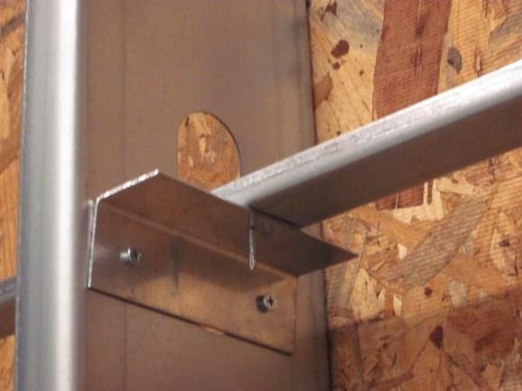
13 and suggestions on the technique to simulate wood sheathed cold-formed steel shear walls was provided. The development of these fastener-based computational models is ongoing. It is important to note that Euler Bernoulli beam theory is applied to the beamcolumn element in Opensees that was used for modeling framing members. Therefore, shear deformation is not taken into account because plane sections remain plane and normal to the neutral axis after bending. In addition, due to the nature of beam-column element, local and distortional buckling are not captured. A more advanced computational modeling is required if the deformation of framing members needs to be focused CFS-NEES Shear Wall Full-Scale Testing The full-scale shear wall tests conducted by Liu et al. (2012a,b) was motivated by the shear walls designed for a two-storey cold-formed steel ledger-framed building (Madsen et al. 2011) that underwent full-scale shake table testing at University at Buffalo (Peterman et al. 2014) as a part of CFS-NEES project. The details of this test series including test setup, loading protocol, test specimens, material properties, and test results are provided as follows. Test setup All of 16 tests were performed on an adaptable structural steel testing frame which is equipped with one MTS 35 kip hydraulic actuator with 5 in. stroke. As depicted in Figure 2.1 (a), a specimen is bolted to the rig via a steel base at the bottom and connected to a structural WT at the top with two lines of self-drilling screws at every 3 in. along the top track. This WT's role is to transfer lateral force from the actuator to the shear wall. A 7
14 series of rollers is employed to provide out-of-plane support at the top of the specimen as shown in Figure 2.1 (c). Five position transducers are placed following the sensor plan provided in Figure 2.1 (b) to measure deflection of the shear wall in the north, south, and lateral directions. 3 Load NORTH SOUTH (a) (b) (c) Figure 2.1. CFS-NEES shear wall test setup (a) testing rig with 4 ft 9 ft specimen, (b) sensor plan, (c) out-ofplane support (Liu et al. 2012a,b) 8
15 Loading protocol Both monotonic and cyclic tests were conducted using displacement control. Monotonic loading procedure is in accordance with ASTM E564(Standard Practice for Static Load Test for Shear Resistance of Framed Walls Buildings). Cyclic loading follows the CUREE protocol which is in accordance with the test method C in ASTM E2126. The utilized CUREE loading procedure with a frequency of 0.2 Hz is provided in Figure CUREE protocol 150 Specimen displacement(% ) Time(s) Figure 2.2. CUREE loading history Test specimens Test matrix is provided in Table shear wall configurations differ in wall size, load type, grade and thickness of field stud, location of seam on OSB, sheathing type, and whether or not ledger is present. The baseline specimen consists of either 4 ft 9 ft or 8 ft 9
16 9 ft cold-formed steel frame sheathed with either oriented strand board (OSB) or gypsum board or both. As depicted in Figure 2.3 (a)-(b), the frame is assembled with 600S (50ksi) studs connected to two 600T (50ksi) tracks with No. 10 flathead screws. Studs are spaced at 24 in. on center and braced with a 1.5 in. 54mil cold rolled channel (CRC) as shown in Figure 2.3 (d). Chord studs consist of two studs connected back-to-back to each other with pairs of No. 10 flathead screws spaced every 12 inches. 1200T (50ksi) track is used for the ledger when ledger is present. Simpson Strong-Tie S/HDU6 hold downs are attached on the inward face at the bottom of the chord studs as shown in Figure 2.3 (e). The OSB used as sheathing in the test is 7/16 in., 24/16 rated, exposure 1. The gypsum board is 4 ft wide and 8 ft tall with 0.5 in. thickness. OSB board is connected to the frame with No. 8 flathead fasteners and No. 6 fasteners are used for attaching gypsum board. The layout of these fasteners for 4 ft 9 ft shear walls is provided in Figure 2.3 (a)-(b). The details are similar for 8 ft 9 ft shear walls. 1.5 in. wide 54 mil strap is employed at horizontal seam of OSB boards. Table 2.1. Test matrix (Liu et al. 2012a) Test Wall Size Load Type F. Sheathing B. Sheathing Stud Ledger H. Seam V. Seam Peak Load Peak Disp. quantity mono/cyclic OSB Gypsum 600S162-xx 1200T P ave Δ ave unit ftxft - /- /- 1/1000 in. /- ft ft plf in 1c 4x9 Monotonic up x9 Cyclic up x9 Cyclic 54 8 up x9 Cyclic up x9 Cyclic up x9 Cyclic up * 4x9 Cyclic up 1 over * 4x9 Cyclic up 2 over x9 Cyclic up 2 over x9 Cyclic up 2' over c 8x9 Monotonic up x9 Cyclic up x9 Cyclic 54 8 up x9 Cyclic up x9 Cyclic up x9 Cyclic up Notes: CUREE protocol employed for cyclic testing, *additional field stud 1' over from side 10
 (d)")
17 (a) (b) (c) (d) 11
 Material properties Coupon tests of the stud and track material were conducted according to the ASTM A370 (2006) Standard Test Methods and Definitions for Mechanical Testing of Steel Products.")
18 (e) Figure 2.3. Shear wall specimen (a) front view of 4 ft 9 ft specimen, (b) back view of 4 ft 9 ft specimen, (c) ledger, (d) wall bracing, (e) hold-down (Peng et al. 2012a,b, Peterman et al. 2014) Material properties Coupon tests of the stud and track material were conducted according to the ASTM A370 (2006) Standard Test Methods and Definitions for Mechanical Testing of Steel Products. A summary of the test results is provided in Table 2.2. Table 2.2. Coupon test summary (Liu et al. 2012a) Uncoated Yield stress Tensile Elongation for 2 in. F thickness F y strength F u /F Components y u gage length (in.) (ksi) (ksi) (%) 54mil-50ksi stud % 54mil-50ksi track % 54mil-50ksi stud* % 33mil-33ksi stud % 54mil-33ksi stud % 97mil-50ksi ledger % Note: 54mil-50ksi stud* is the second set of purchased studs which were used in all the 8ft x 9ft shear walls as a field stud. 12
19 Test results Table 2.3 provides a summary of the shear wall test results. In summary, failure typically occurred at sheathing-to-frame connection locations. Practical details including ledger track, interior gypsum board, panel seams, grade and thickness of field stud are demonstrated to have a great impact on the specimens shear capacity. Finally, measured capacity exceeded the nominal capacity specified in the design code AISI-S Table 2.3. Summary of shear wall test results (Liu et al. 2012a) Test Peak Load Lateral Deflection at Peak Avg. Load 1 Avg. Disp 2 Failure Mode 3 quantity P+ P- Δ+ Δ- P ave Δ ave unit plf plf in. in. plf in. - 1c PT PT PT PT PT PT 7* PT 8* PT PT PT 11c PT+B PT+B PT+B PT+B PT PT 1 Average of P+ and P-, 2 Average of Δ+ and Δ-, 3 PT = fastener pull-through and B = fastener bearing *Additional filed stud 1'over from side 13
20 Chapter 3 - High Fidelity Computational Modeling 3.1. Introduction The ability to perform advanced computational modeling is essential for the development of performance-based seismic design methods of cold-formed steel structures in general and cold-formed steel shear walls in particular. This chapter presents a reliable modeling protocol that can be used to accurately simulate a wood-sheathed cold-formed steel shear wall using the Abaqus software. This modeling protocol will not only enable engineers to predict the lateral capacity but also provide a thorough insight into the failure mechanism of the wood-sheathed cold-formed steel shear wall subjected to lateral loading. This modeling protocol is developed based on the effort of reproducing the full-scale cold-formed steel shear wall tests conducted by Liu et al. (2012a,b) as summarized in Chapter 2. Specifically, a series of ten high fidelity shell finite element models are initiated in Abaqus to simulate ten shear wall specimens of which details are shown in Table 3.1. Each of the following sections will describe the modeling of one or more components in the specimen. 14
21 Table 3.1. Model matrix Model Num. Test Num. Wall Size Load Type F. Sheathing B. Sheathing Stud Ledger quantity mono/cyclic OSB Gypsum 600S162-xx 1200T unit ftxft - /- /- 1/1000 in. /- 1 1c 4x9 Monotonic x9 Cyclic x9 Cyclic x9 Cyclic c 8x9 Monotonic x9 Cyclic x9 Cyclic x9 Cyclic x9 Cyclic x9 Cyclic - 54 Notes: CUREE protocol employed for cyclic testing 3.2. General Model Details Figure 3.1 shows the assembly of a 4ft 9ft and a 8ft 9ft shear wall in Abaqus. The specimen geometry and practical details including the use of ledger (rim track), interior gypsum board, and smaller thickness for field stud follow that of Liu et al. (2012a) as summarized in Table 3.1 and Table 3.2. Herein, for all ten finite element models, nonlinear collapse pushover analysis is conducted. Newton-Raphson numerical method is used for solving nonlinear equations. In this research, seam on sheathing is ignored. Geometric imperfections, residual stresses and strains are not included. Table 3.2. General model details Stud 600S162-54; 9ft Track 600T150-54; 4ft or 8ft OSB Panel 7/16" thick, 24/16 rated, exposure 1 Gypsum Panel 1/2" thick Hold-Down S/HDU6 15

 studied the sensitivity to element choice and mesh in the computational modeling of cold-formed steel and demonstrated that the mesh density has a great impact on the response of coldformed")
22 (a) (b) Figure 3.1. Assembly of (a) 4ft 9ft and (b) 8ft 9ft shear wall in Abaqus 3.3. Element and Mesh Discretization Cold-formed steel framing members and sheathing are modeled as four-node shell finite elements S4R in Abaqus. This type of element uses linear shape functions and has reduced integration scheme to prevent shear blocking in coarse mesh. Five integration points are utilized through the thickness of the element. Schafer et al. (2010) studied the sensitivity to element choice and mesh in the computational modeling of cold-formed steel and demonstrated that the mesh density has a great impact on the response of coldformed steel members in finite element analysis. A coarse mesh can be adequate for capturing the distortional and global buckling modes but cannot accurately reproduce local buckling modes. On the other hand, a medium or fine mesh can represent all 16
23 buckling modes including local, distortional, and global with reasonable accuracy. In addition, once a reasonable mesh is used, the difference in response between different type of element becomes small. For these reasons, as depicted in Figure 3.2, a relatively fine mesh is used in this modeling effort. A code is written in Matlab to generate the mesh for the model with a seed size corresponding to 0.25 inch in real length used for steel members and a seed size corresponding to 2 inches in real length used for sheathing. This mesh discretization allows two elements on the lip of the stud so that local buckling can be reproduced if occurs at these locations. Aspect ratio of the elements is kept as close to one as practical and limited to be smaller than 2.5. (a) Stud (b) Track (c) Ledger (d) Sheathing Figure 3.2. Shell finite element mesh of (a) stud, (b) track, (c) ledger, and (d) sheathing 17
24 3.4. Material Properties As depicted in Table 3.3, cold-formed steel is modeled as isotropic elastic with Young's modulus E=29,500ksi and Poisson's ratio v= 0.3. This value for Young's modulus E=29,500ksi is commonly used in the computational modeling of cold-formed steel. According to Abaqus analysis user's guide, this type of material is adequate since elastic strains are expected to be small (less than 5%). Both sheathing material, oriented strand board (OSB) and gypsum, are modeled as isotropic elastic with a large Young's modulus E=30,000ksi and Poisson's ratio v= 0.3 to minimize diaphragm deformations. Table 3.3. Material modeling Material Young's Modulus Poisson's ratio Quantity E v Unit (ksi) Steel 29, OSB 30000* 0.3 Gypsum 30000* 0.3 * Rigid assumption 3.5. Out-of-Plane Support The out-of-plane support of the top track in the experiments as described in Chapter 2 was included in the model as transverse roller constraints. As depicted in Figure 3.3, two lines of nodes on the web of the top track at the exact location of the screws connecting the top of shear wall specimen to the structural WT member are fixed in the transverse direction. The purpose of this constraint is to restrict the shear wall to in-plane movement. 18
25 Figure 3.3. Modeling of out-of-plane support 3.6. Anchor Bolt Figure 3.4 shows the modeling of anchor bolt in Abaqus. The anchor bolts connecting the bottom track to the foundation are modeled as pinned connections by fixing the nodes at the bolt locations in both horizontal and transverse direction. This allows force in the shear wall to transfer directly to the foundation in these two directions. Figure 3.4. Modeling of anchor bolt 19
26 3.7. Hold-Down The modeling of hold-down is depicted in Figure 3.5. First, all the nodes in the areas on the web of chord studs which are connected to the hold-down in the test are bound into a rigid body and a single node at the centroid of these areas is assigned to the rigid body using the RIGID BODY command in Abaqus. As a result, the motion of this collection of nodes will be governed by the motion of the rigid body reference node. Therefore, the relative positions between the constituent nodes remain constant during the simulation and the whole area does not deform but undergoes a rigid body motion. Second, the rigid body reference node is connected to a node on the ground in the vertical direction via a bi-linear spring. This modeling choice is based on the study of Buonopane et al. (2014) in which the necessity of modeling the tension flexibility of the hold-down is demonstrated. Herein, the tension stiffness of the hold-down is selected to be 56.7 kips/in based on Leng et al. (2013). The compression stiffness is chosen to be 1000 times larger than the tension stiffness based on the assumption that axial force in chord studs is transferred rigidly to the foundation when the hold-down is in compression. The bi-linear spring connecting the reference node to a node on the ground is modeled by means of nonlinear spring element type SPRING2 in Abaqus. This type of element is used to connect two nodes and allows the definition of nonlinear behavior for a fixed degree of freedom of interest. This nonlinear behavior can be defined by providing pairs of forcerelative displacement values. It is important to note that these values need to be given in ascending order of relative displacement. Also, a non-zero force needs to be assigned at zero relative displacement. 20
27 Figure 3.5. Modeling of hold-down 3.8. Steel-to-Steel Connection Figure 3.6 shows the modeling of the cold-formed steel frame connections in the shear wall including the fasteners connecting (i) a stud to a track, (ii) a stud to another stud in back-to-back chord studs, and (iii) a ledger to a stud. These steel-to-steel connections are modeled as pinned by means of multi-point constraints (MPC) type PIN in Abaqus. This MPC makes all three translational displacements of the two nodes on two separate steel members to be connected equal but leaves the rotations independent of each other. In Abaqus, this MPC is imposed by eliminating three translational degrees of freedom at the first node, which is called the "dependent node". The second node of which the translational degrees of freedom are not eliminated is called the "independent node". It is important to note that in Abaqus, a node can only be used as a dependent node for one time. In other words, a node that has already been used as the first node in an MPC definition should not be used subsequently to impose any constraints as an independent node. 21
28 (a) (b) (c) Figure 3.6. Modeling of (a) leger-to-stud connections, (b) stud-to-track connections, and (c) stud-to-stud connectionss 22
29 3.9. Sheathing-to-Frame Connections The sheathing-to-frame connections, i.e. the fasteners connecting the sheathing to the cold-formed steel frame are modeled as springs by means of nonlinear spring element type SPRINGA in Abaqus. This type of element acts as an axial spring connecting two nodes defined by the user, whose line of action is the line joining these two nodes. For geometrically nonlinear analysis the relative displacement across a SPRINGA element is the change in length in the spring between the initial and the current configuration. For this reason, as shown in Figure 3.7, this modeling can accurately reproduce the behavior of the sheathing-to-frame connection which is isotropic in the plane of the sheathing if the initial distance between the two nodes is set to be small. Specifically, once the shear wall specimen is subjected to lateral displacement, node number 2 on steel frame moves from its initial location to the new location at node 2'. The new line of action of the spring will then be recalculated based on the updated coordinates of the two nodes. This newly updated line of action can be approximated to be aligned with the direction of the force crosses from the steel frame through the fastener to the sheathing when the initial distance between the two nodes is small enough to be considered negligible. Herein, this initial distance is set to be inch which is more than 2000 times smaller than the maximum elastic strain. The nonlinear behavior in the line of action of the spring element type SPRINGA follows the backbone curves as shown in Table 3.4. These backbone curves are for sheathing-toframe connections connecting steel frame to OSB or gypsum obtained from the monotonic and cyclic fastener tests conducted by Peterman et al. (2013). Herein, only 23

30 the backbone is implemented. The "pinched" or reloading/un-loading behavior is not incorporated. Figure 3.7. Use of SPRINGA element as a multiple shear spring Table 3.4. Backbone points of sheathing-to-frame connections Tension Compression Sheathing u1 u2 u3 u4 F1 F2 F3 F4 u F in. in. in. in. kip kip kip kip in. kip Monotonic for OSB Cyclic for OSB Symmetric Cyclic for Gypsum Loading Model In this model, lateral loading is applied to the top of the shear wall with displacementcontrol. As shown in Figure 3.8, one end cross-section of the top track is tied to a reference node at its centroid using the RIGID BODY command in Abaqus, which is already described in Section 3.7. A displacement of 4 inches in the horizontal direction is imposed to this rigid body reference node as a displacement boundary condition. 24

31 Figure 3.8. Modeling of loading 25
32 Chapter 4 - Computational Results and Discussion A series of ten high fidelity shell finite element models are initiated in Abaqus to reproduce ten full-scale shear wall tests conducted by Liu et al. (2012a) using the modeling protocol as presented in Chapter 3. This chapter provides the computational results of the nonlinear collapse pushover analyses of these developed models and compares with the experimental results. Specifically, Section 4.1 shows the forcedisplacement response, peak load, and lateral deflection at peak load for each model compared with the experimental result. Section 4.2 provides an insight into the failure of sheathing-to-frame connections. Section 4.3 shows the deformation of cold-formed steel frame members. Finally, Section 4.4 summarizes the computational results and provides suggestion for the preparation for future full-scale shear wall tests Force-Displacement Response Figures 4.1 (a)-(j) show the nonlinear response of the developed computational models compared with experimental results. Figure 4.1 (a) and (e) are for model 1 and model 5 which reproduce monotonic tests while the rest reproduces cyclic tests. A summary of computational results including peak load and the corresponding lateral displacement is provided in Table 4.1. Overall, the shell finite element models predict the peak load with reasonable accuracy. Except for model 9 which will be discussed later, the finite element models provide a conservative prediction of the peak load for the specimens only sheathed by OSB and provide an optimistic prediction for the specimens in which gypsum board is also included. This suggests modeling gypsum board with its actual material properties 26
33 instead of the current assumption of semi-rigid diaphragm might create a more accurate load distribution to the fasteners and provide a more encouraging and conservative prediction of peak load for these models with gypsum board included. As for model 9, while the specimen is not sheathed with gypsum board, the peak load obtained from the finite element model is optimistic (13%). Compared with model 8, the only difference in test configuration is a smaller thickness of 33mils is used for field studs instead of a typical thickness of 54mils as used in all other tests. As shown in Table 4.1, the peak load obtained from computational modeling slightly decreases from 992plf to 974plf when the thickness of field studs is reduced. However, this decrease is still too small compared to the sudden drop in measured stiffness (peak load dropped from 1023plf down to 861plf) and results in an optimistic prediction of peak load. It is possible that the impact of the field studs on the shear wall's overall response is not enough accurately captured since the vertical OSB seam on the middle field stud is not included in the model. It is also possible that the source of this discrepancy comes from the test results when only one specimen is tested for each shear wall configuration. As described by Liu et al. (2012a), this particular test with small thickness of field studs is an exception whose capacity does not exceed or is within expected scatter (5%) of the shear strength specified by design code. One can suggest conducting more tests with this configuration in order to have a more thorough understanding of the impact of field stud size on a shear wall's lateral capacity. In general, the developed finite element models can accurately capture the initial stiffness but become overly stiff afterwards. As a result, the lateral deflections at peak load obtained from the developed models are somewhat smaller than the experimental values. 27
34 The likely source of this error is the hold-downs. In the shell finite element models, holddowns are modeled as springs located at the bottom areas on chord studs' web. This does not take into account moment of the couple consisting of axial force in chord studs and reaction force on the hold-down rod from the foundation because in the tests, the anchor rod connecting hold-down to the foundation is slightly offset from the line along chord studs' web. In addition, in some models, the analysis halts after the specimen reaches its peak load due to convergence difficulty. Table 4.1. Summary of computational results Model Test Pcomp/Ptest Computational Result Experimental Result Peak Load Lateral Deflection* Peak Load Lateral Deflection* quantity P Δ P Δ unit plf in. plf in. 1 1c c * Lateral deflection at peak load 28
35 (a) (b) (c) (d) (e) (f) 29
36 (g) (h) (i) (j) Figure 4.1. Nonlinear response of computational models compared with experimental results: (a)-(j) for model 1- model Sheathing-to-Frame Connection Failure The developed finite element models allow the assessment of the manner in which shear force in the shear wall is distributed to the fasteners. In particular, Figure 4.2 shows the deformed shape of model 4 at the end of analysis with a focus on the deformation of the sheathing-to-frame fasteners. Deformed shapes for all other models are provided in Appendix A. Figures 4.3 (b)-(c) show the fastener force-overall lateral displacement 30

37 curve for some typical fasteners on left chord studs, field stud, and bottom track. The location of these particular fasteners is provided in Figure 4.3 (a). Nonlinear response of fasteners on top track and chord studs on the right side is not shown in the figures due to the symmetry. Force in fasteners on chord studs and tracks at the corner reaches its peak when the overall shear wall specimen reaches its peak load at the lateral displacement of approximately 1.75in. Fasteners at the middle of chord studs pass their maximum force a little later at the overall lateral displacement of approximately 2in. The closer the fastener on track is to the field stud, the less force is distributed to it. Fasteners at the middle of tracks have not reached their maximum force and did not fail even at the end of analysis. In the similar manner, failure at fasteners on field stud was not observed. Especially, very little force is distributed to the fasteners at the middle of field stud. One interesting observation from the deformed shape of model 4 is all the fasteners tend to deform in the vertical direction. Figure 4.2. Deformed shape of model 4 at the end of analysis (Scale factor: 2) 31
 (b)")
38 (a) (b) 32
39 (c) Figure 4.3. (a) Fastener location, (b) force in fasteners on stud, (c) force in fasteners on track 4.3. Deformation of Cold-Formed Steel Frame Members One advantage of the developed high fidelity shell finite element models over other nonlinear models is the ability to capture all the buckling modes of the cold-formed steel frame members and visually represent the deformed shape and stress distribution in the shear wall. In particular, Figure 4.4 (a)-(c) provides the von Mises stress contour plotted on deformed shape of the specimen for model 4 at peak load. Rainbow color spectrum from red (for the maximum value) to blue (for the minimum value) is used to represent contour values. Grey color is used to represent the area whose stress being higher than the maximum value. Von Mises stress is commonly used in determining whether an isotropic 33

40 metal yields when subjected to a complex loading condition. In this research, although cold-formed steel members are modeled as elastic, the plotted contours can suggest where to expect yielding to happen in the shear wall by setting the maximum limit for the contour as material's yield stress. In particular, the maximum limit for the contours provided in Figure 4.4 was set to be 50 ksi which is the actual yield stress of the coldformed steel used for the test. The plots show a large stress concentration on the flanges of tracks near the stud-to-track connection (represented by grey color) and indicate that these areas should be expected to yield according to von Mises Yield Criterion. One might suggest employing strain gauges to further explore the deformation of steel members at these locations in future testing. (a) 34

 top, and (c) bottom of specimen for")
41 (b) (c) Figure 4.4. Von Mises stress contour plotted on deformed shape of the (a) whole specimen, (b) top, and (c) bottom of specimen for model 4 at peak load (Scale factor: 2) 35
42 4.4. Summary Chapter 4 provided the computational results for ten high fidelity shell finite element models whose protocol is detailed in Chapter 3. Overall, the developed models can predict the peak load with reasonable accuracy but is overly stiff. The failure mechanism of sheathing-to-frame connections and deformation of cold-formed steel frame members were also presented. 36

43 Chapter 5 - Experimental Setup This chapter details the experimental setup for future full-scale shear wall tests. Specifically, modified testing rig, sensor plan, loading protocol, assembly of typical test specimen, and preparation for future material testing will be presented Testing Rig The Johns Hopkins University multi-degree of freedom testing rig, which is called Big Blue Baby, will be used for conducting future full-scale shear wall tests. As depicted in Figure 5.1, this rig consists of one horizontal hydraulic actuator, two lateral hydraulic actuators, and four vertical hydraulic actuators. This allows the specimen to be loaded with any combinations of axial load, shear, and bending. Figure 5.1. Modified Big Blue Baby with 8 ft 8ft shear wall specimen 37
44 Design of top and bottom steel tubes In order to connect the shear wall specimen to the rig, one steel tube at the top and one steel tube at the bottom were designed and fabricated. As depicted in Figures 5.2 (a)-(b), holes were drilled on the top and bottom surface of each tube so that one can connect these tubes to the Big Blue Baby and bolt the specimen's tracks to these tubes prior to the test. Both tubes have cut-outs along the length to provide access to the bolts just mentioned. The design of two steel tubes was conducted in a conservative manner based on the limit states of moment yielding, shear yielding, and deflection taking into consideration of the hold-down force and gravity load applied to the specimen. Rectangular hollow structural section (HSS) /2 was used for both two tubes. Detailed drawings of these tubes are provided in Appendix B. 38
 top tube, (b) bottom tube Design of steel bars for hold-downs and steel plates During the")

45 (a) (b) Figure 5.2. Modification to existing testing rig (a) top tube, (b) bottom tube Design of steel bars for hold-downs and steel plates During the test, a large force is expected be transferred from the specimen to the steel tube passing hold-down anchor rod. The concentration of this hold-down force on a small area on steel tube at the location of hold-down anchor rod can cause significant deformation. For this reason, steel bars were designed to distribute this force to a larger area on tubes as described in Figure 5.3 (a)-(b). 39

 will be placed between specimen and the steel tubes.")
46 In order to avoid the contact between sheathing and the testing rig during the test, steel plates are designed and fabricated. These steel plates, as shown in Figure 5.3 (c) will be placed between specimen and the steel tubes. Detailed drawings of these steel bars and plates are provided in Appendix B. (a) (b) 40

47 (c) Figure 5.3. (a)-(b) Steel bars for hold-downs, (c) steel plates 5.2. Instrumentation Plan Eight sensors were employed to measure the response of the specimen under loading. Sensor layout and numbering scheme are provided in Figure 5.4. Position transducers 1 and 2 measure lateral displacement at the top and bottom of the shear wall. Relative displacement between chord stud ends and tracks in vertical direction are captured by position transducers 3,4,5, and 6. Position transducers 7 and 8 record vertical motion of the loading beam. As depicted in Figure 5.5, seven position transducers are installed using magnetic mounting base. Only position transducer 2 is mounted on a plastic plate which is clamped to the bottom tube. One advantage of this sensor plan is that some sensors do not have to be removed and reinstalled between tests. Also, due to the use of magnetic mounting base, the installation is quick and simple. 41

48 Figure 5.4. Instrumentation plan Figure 5.5. Installation of position transducer 42
49 5.3. Load Protocol All of the shear walls are subjected to a combination of lateral and vertical loads using displacement control. Lateral loading can either be monotonic or cyclic. Monotonic test is first conducted in order to determine the ultimate displacement which will be used as target maximum deformation for cyclic test. Cyclic loading is in accordance with the FEMA 461 quasi-static cyclic testing protocol. This protocol is chosen because it can be used to obtain not only fragility data but also data on the hysteretic characteristics of the structural components of which damage is best predicted by imposed deformations. FEMA 461 protocol consists of steps with increasing amplitude and two identical cycles need to be completed for each amplitude. Amplitude of one step is 1.4 times larger than that of the previous step. Lateral displacement at the top of the shear wall is used as deformation control parameter. The FEMA 461 protocol is defined in order that a deformation associated with the most severe damage state (ultimate displacement measured from monotonic test) is reached at the 10th step. Further information can be found at "Interim Testing Protocols for Determining the Seismic Performance Characteristics of Structural and Nonstructural Components" (2007) Typical Test Specimen Figures 5.6 (a),(b) depict the dimension and fastener schedule for 4ft 8ft and 8ft 8ft shear wall specimen. Figure 5.7 shows a typical 4ft 8ft shear wall specimen assembled by the author and colleagues at Thin-walled Structures Laboratory, Johns Hopkins University. 43

50 (a) (b) Figure 5.6. Drawing of (a) 4ft 8ft, (b) 8ft 8ft shear wall specimens Figure 5.7. Assembly of 4ft 8ft shear wall specimen at Thin-walled Structures Laboratory, Johns Hopkins University 44
 and then precision machined into tensile coupons as depicted in Figure 5.")

51 5.5. Material Properties In order to prepare for future material tensile testing, specimens were cut from the webs of cold-formed steel channel sections (362S [50ksi] and 362T [50ksi]) and then precision machined into tensile coupons as depicted in Figure 5.8 (a). Specifically, three coupons were obtained from one cold-formed steel member. These uncoated coupons will be tested using the MTS machine shown in Figure 5.8 (b). (a) (b) Figure 5.8. Preparation for material tensile testing (a) tensile specimens, (b) MTS machine 45
52 Chapter 6 - Future Work The high fidelity computational models described herein were demonstrated to be able to simulate wood-sheathed cold-formed steel shear walls with reasonable accuracy. However, this developed modeling protocol can be further improved by (i) modeling gypsum board with its actual material properties, (ii) incorporating unloading/reloading (pinching) behavior so that the full non-linear cyclic response can be reproduced, (iii) explicitly modeling the hold-downs to take into account the hold-down force eccentricity, and (iv) including geometric imperfections, residual stresses and strains. As the continuation of the first phase, phase two of the overall project needs to be conducted. The scope of phase 2 is as follows. (a) Parametric study of wood-sheathed cold-formed steel framed shear walls with nonconventional detailing based on developed modeling protocol (b) Full-scale testing on wood-sheathed cold-formed steel framed shear walls with nonconventional detailing 46
53 Chapter 7 - Conclusions The objective of the overall project is to explore limit states other than those associated with the fastener, such as chord buckling, in the wood-sheathed cold-formed steel framed shear wall so that reliability of this complex subsystem can formally be evaluated based on potential limit states. This thesis presented phase 1 of this project focusing on the development of high fidelity computational modeling of wood-sheathed cold-formed steel framed shear walls and preparation for future full-scale shear wall testing. A series of ten high fidelity shell finite element models were initiated in Abaqus to simulate ten CFS-NEES shear wall specimens tested by Liu et al. (2012a,b). The developed modeling protocol was demonstrated to be able to capture lateral capacity with reasonable accuracy. The predicted strength was conservative for the shear walls only sheathed by OSB and slightly optimistic when gypsum board is also included. In general, initial stiffness was accurately captured but the models became overly stiff afterwards. As a result, lateral deflections at peak load obtained from the developed models were somewhat smaller than the experimental values. In addition, failure mechanism of sheathing-to-frame connections and deformation of cold-formed steel frame members were presented. A large stress concentration was observed at the flanges of tracks near the stud-to-track connection. While improvements are recommended, the agreement in response with the tests was considered encouraging given that the fastener data were obtained from tests conducted completely independently from Liu et al. (2012a,b)'s tests. 47
54 Experimental setup for future full-scale shear wall testing was also presented. Specifically, modified testing rig, sensor plan, loading protocol, assembly of typical test specimen, and preparation for future material testing were described. As the continuation of the research presented herein, phase two of the overall project including parametric study and full-scale testing on shear walls with non-conventional detailing are underway. 48
55 Appendix A - Deformed Shape Of Computational Models 49
")
56 Figure A.1. Deformed shape of model 1c at the end of analysis (Front view, scale factor: 2) Figure A.2. Deformed shape of model 2 at the end of analysis (Front view, scale factor: 2) 50
57 Figure A.3. Deformed shape of model 3 at the end of analysis (Front view, scale factor: 2) Figure A.4. Deformed shape of model 4 at the end of analysis (Front view, scale factor: 2) 51
 Figure A.6.")
58 Figure A.5. Deformed shape of model 11c at the end of analysis (Front view, scale factor: 2) Figure A.6. Deformed shape of model 12 at the end of analysis (Front view, scale factor: 2) 52
59 Figure A.7. Deformed shape of model 13 at the end of analysis (Front view, scale factor: 2) Figure A.8. Deformed shape of model 14 at the end of analysis (Front view, scale factor: 2) 53
 Figure A.10.")
60 Figure A.9. Deformed shape of model 15 at the end of analysis (Front view, scale factor: 2) Figure A.10. Deformed shape of model 16 at the end of analysis (Back view, scale factor: 2) 54
Cold-formed steel shear walls in ledger-framed buildings
 Proceedings of the Annual Stability Conference Structural Stability Research Council Grapevine, Texas, April 18-21, 2012 Cold-formed steel shear walls in ledger-framed buildings P. Liu 1, K.D. Peterman
Fastener-Based Computational Models with Application to Cold-Formed Steel Shear Walls
 Missouri University of Science and Technology Scholars' Mine International Specialty Conference on Cold- Formed Steel Structures (2014) - 22nd International Specialty Conference on Cold-Formed Steel Structures
research report Performance of Cold-Formed Steel-Framed Shear Walls: Alternative Configurations RESEARCH REPORT RP REVISION 2006
 research report Performance of Cold-Formed Steel-Framed Shear Walls: Alternative Configurations RESEARCH REPORT RP2-7 22 REVISION 26 American Iron and Steel Institute Performance of Cold-Formed Steel-Framed
NOMINAL SHEAR STRENGTH OF COLD-FORMED STEEL SHEAR WALLS USING OSB SHEATHING. Chao Li. Thesis Prepared for the Degree of MASTER OF SCIENCE
 NOMINAL SHEAR STRENGTH OF COLD-FORMED STEEL SHEAR WALLS USING OSB SHEATHING Chao Li Thesis Prepared for the Degree of MASTER OF SCIENCE UNIVERSITY OF NORTH TEXAS May 212 APPROVED: Cheng Yu, Major Professor
COMBINED ADHESIVE-STEEL PIN APPLICATIONS FOR CFS FRAME SHEAR WALLS
 Department of Civil Engineering Santa Clara University COMBINED ADHESIVE-STEEL PIN APPLICATIONS FOR CFS FRAME SHEAR WALLS Final Report: CLFSR-5-4 May 31, 24 By Ioi Lam, Henry Qi and Christopher Pitt (Undergraduate
Fastener-Based Computational Models of Cold- Formed Steel Shear Walls
 Bucknell University Bucknell Digital Commons Honors Theses Student Theses 2014 Fastener-Based Computational Models of Cold- Formed Steel Shear Walls Thet Hein Tun Bucknell University, tht001@bucknell.edu
TECHNICAL NOTE. Design of Diagonal Strap Bracing Lateral Force Resisting Systems for the 2006 IBC. On Cold-Formed Steel Construction INTRODUCTION
 TECHNICAL NOTE On Cold-Formed Steel Construction 1201 15th Street, NW, Suite 320 W ashington, DC 20005 (202) 785-2022 $5.00 Design of Diagonal Strap Bracing Lateral Force Resisting Systems for the 2006
research report Estimating the Response of Cold-Formed Steel Frame Shear Walls RESEARCH REPORT RP REVISION 2006
 research report Estimating the Response of Cold-Formed Steel Frame Shear Walls RESEARCH REPORT RP03-7 2003 REVISION 2006 American Iron and Steel Institute Estimating the Response of Cold-Formed Steel Frame
Seismic design of braced frame gusset plate connections
 Earthquake Resistant Engineering Structures V 105 Seismic design of braced frame gusset plate connections C. W. Roeder, D. E. Lehman, A. Christopolus, I. Gunnarson, S. Johnson & J. H. Yoo Department of
BRACING STIFFNESS AND STRENGTH IN SHEATHED COLD-FORMED STEEL STUD WALLS
 SDSS Rio 2010 STABILITY AND DUCTILITY OF STEEL STRUCTURES E. Batista, P. Vellasco, L. de Lima (Eds.) Rio de Janeiro, Brazil, September 8-10, 2010 BRACING STIFFNESS AND STRENGTH IN SHEATHED COLD-FORMED
SEISMIC BEHAVIOR OF STEEL RIGID FRAME WITH IMPERFECT BRACE MEMBERS
 INTERNATIONAL JOURNAL OF CIVIL ENGINEERING AND TECHNOLOGY (IJCIET) International Journal of Civil Engineering and Technology (IJCIET), ISSN 976 638 (Print), ISSN 976 6316(Online), Volume 6, Issue 1, January
Monotonic Tests of Long Shear Walls with Openings
 Monotonic Tests of Long Shear Walls with Openings Virginia Polytechnic Institute and State University Department of Wood Science and Forests Products Brooks Forest Products Research Center Timber Engineering
Overview of Presentation. SCBFs are Conceptually Truss Structures
 Ultimate Strength and Inelastic Behavior of Braced Frame Gusset Plate Connections Charles W. Roeder University of Washington Department of Civil and Environmental Engineering Seattle, WA 98195 Structural
TECHNICAL NOTE On Cold-Formed Steel Construction
 TECHNICAL NOTE On Cold-Formed Steel Construction 1201 15th Street, NW, Suite 320 Washington, DC 20005 (202) 785-2022 $5.00 Changes from the 1997 UBC to the 2006 IBC for Lateral Design with Cold-Formed
QUALITY CONTROL TESTING OF PLASTERBOARD FOR BRACING APPLICATIONS. Y L Liew Vicroads Victoria, Australia
 Int. Journal for Housing Science, Vol.32, No.1 pp. 51-60, 2008 Published in the United States QUALITY CONTROL TESTING OF PLASTERBOARD FOR BRACING APPLICATIONS Y L Liew Vicroads Victoria, Australia E F
Finite Element Modeling of New Composite Floors Having Cold-Formed Steel and Concrete Slab
 Missouri University of Science and Technology Scholars' Mine International Specialty Conference on Cold- Formed Steel Structures (2014) - 22nd International Specialty Conference on Cold-Formed Steel Structures
CYCLIC TESTING OF BOLTED CONTINUOUS I-BEAM-TO-HOLLOW SECTION COLUMN CONNECTIONS
 10NCEE Tenth U.S. National Conference on Earthquake Engineering Frontiers of Earthquake Engineering July 21-25, 2014 Anchorage, Alaska CYCLIC TESTING OF BOLTED CONTINUOUS I-BEAM-TO-HOLLOW SECTION COLUMN
Modelling the seismic response of light-timber-framed buildings
 Modelling the seismic response of light-timber-framed buildings B.L. Deam & P.J. Moss Wood Technology Research Centre and Department of Civil Engineering, University of Canterbury, Christchurch NZSEE 2001
Analysis of Shear Wall Transfer Beam Structure LEI KA HOU
 Analysis of Shear Wall Transfer Beam Structure by LEI KA HOU Final Year Project report submitted in partial fulfillment of the requirement of the Degree of Bachelor of Science in Civil Engineering 2013-2014
INTERNATIONAL JOURNAL OF CIVIL AND STRUCTURAL ENGINEERING Volume 2, No 2, 2011
 INTERNATIONAL JOURNAL OF CIVIL AND STRUCTURAL ENGINEERING Volume 2, No 2, 2011 Copyright 2010 All rights reserved Integrated Publishing services Research article ISSN 0976 4399 Nonlinear Seismic Behavior
Nonlinear Redundancy Analysis of Truss Bridges
 Nonlinear Redundancy Analysis of Truss Bridges Analysis Report Dr. Michel Ghosn Ph.D. Graziano Fiorillo The City College of New York / CUNY SEPTEMBER 2013 Acknowledgments This section describes the redundancy
Fagà, Bianco, Bolognini, and Nascimbene 3rd fib International Congress
 COMPARISON BETWEEN NUMERICAL AND EXPERIMENTAL CYCLIC RESPONSE OF ALTERNATIVE COLUMN TO FOUNDATION CONNECTIONS OF REINFORCED CONCRETEC PRECAST STRUCTURES Ettore Fagà, Dr, EUCENTRE, Pavia, Italy Lorenzo
Nonlinear Finite Element Modeling & Simulation
 Full-Scale Structural and Nonstructural Building System Performance during Earthquakes & Post-Earthquake Fire A Joint Venture between Academe, Industry and Government Nonlinear Finite Element Modeling
STIFFNESS AND STRENGTH OF SINGLE SHEAR COLD-FORMED STEEL SCREW-FASTENED CONNECTIONS
 STIFFNESS AND STRENGTH OF SINGLE SHEAR COLD-FORMED STEEL SCREW-FASTENED CONNECTIONS by Hong S. Pham, Graduate Research Assistant Cristopher D. Moen, Ph.D., P.E. Report No. CE/VPI-ST-15-07 June 2015 TABLE
research report Cold-Formed Steel Walls with Fiberboard Sheathing Shear Wall Testing RESEARCH REPORT RP REVISION 2006
 research report Cold-Formed Steel Walls with Fiberboard Sheathing Shear Wall Testing RESEARCH REPORT RP05-3 2005 REVISION 2006 American Iron and Steel Institute Cold-Formed Steel Walls with Fiberboard
Dynamic Stability of Elastomeric Bearings at Large Displacement
 Dynamic Stability of Elastomeric Bearings at Large Displacement A. Masroor, J. Sanchez, G. Mosqueda University at Buffalo, NY, USA K. L. Ryan University of Nevada, Reno, USA SUMMARY: Bearings used in the
Structural vs Nonstructural Members. Roger LaBoube, Ph.D., P.E. Wei-Wen Yu Center for Cold-Formed Steel Structures
 Structural vs Nonstructural Members Roger LaBoube, Ph.D., P.E. Wei-Wen Yu Center for Cold-Formed Steel Structures Behavior of Cold-Formed Steel Members STEEL DESIGN SPECIFICATIONS Type of steel Specification
Seismic behaviour of timber shear walls with loadlimiting slip-friction connectors
 Seismic behaviour of timber shear walls with loadlimiting slip-friction connectors W. Y. Loo, P. Quenneville & N. Chouw Department of Civil and Environmental Engineering, University of Auckland, Auckland,
Analysis of Sheathed Cold-Formed Steel Wall Studs
 Sixteenth International Specialty Conference on Cold-Formed Steel Structures Orlando, Florida U.S.A., October 17-18, 2002 Analysis of Sheathed Cold-Formed Steel Wall Studs Benjamin W. Schafer 1, Badri
Modelling of RC moment resisting frames with precast-prestressed flooring system
 Modelling of RC moment resisting frames with precast-prestressed flooring system B.H.H. Peng, R.P. Dhakal, R.C. Fenwick & A.J. Carr Department of Civil Engineering, University of Canterbury, Christchurch.
Cyclic Tests of Long Shear Walls with Openings
 Cyclic Tests of Long Shear Walls with Openings Virginia Polytechnic Institute and State University Department of Wood Science and Forests Products Brooks Forest Products Research Center Timber Engineering
FINITE ELEMENT INVESTIGATION AND DESIGN RECOMMENDATIONS FOR PERFORATED STEEL PLATE SHEAR WALLS ABSTRACT
 Proceedings of the 9th U.S. National and 10th Canadian Conference on Earthquake Engineering Compte Rendu de la 9ième Conférence Nationale Américaine et 10ième Conférence Canadienne de Génie Parasismique
LATERAL LOAD BEHAVIOR OF UNBONDED POST-TENSIONED HYBRID COUPLED WALLS. Qiang SHEN Graduate Research Assistant. Yahya C. KURAMA Assistant Professor
 LATERAL LOAD BEHAVIOR OF UNBONDED POST-TENSIONED HYBRID COUPLED WALLS Qiang SHEN Graduate Research Assistant Yahya C. KURAMA Assistant Professor University of Notre Dame, Civil Engineering and Geological
An experimental investigation of local web buckling strength and behaviour of compressive flange coped beam connections with slender web
 An experimental investigation of local web buckling strength and behaviour of compressive flange coped beam connections with slender web Michael C. H. Yam 1), *Ke Ke 2), Angus C. C. Lam 3), Cheng Fang
Cold-Formed Steel Special Bolted Moment Frames: Cyclic Testing and Numerical Modeling of Moment Connections
 Cold-Formed Steel Special Bolted Moment Frames: Cyclic Testing and Numerical Modeling of Moment Connections by Chia-Ming Uang 1, Jong-Kook Hong 2, Atsushi Sato 3 and Ken Wood 4 ABSTRACT Cyclic tests on
Seismic Performance and Design of Linked Column Frame System (LCF)
") Seismic Performance and Design of Linked Column Frame System (LCF) M. Malakoutian & J.W. Berman Department of Civil and Environmental Engineering, University of Washington, Seattle, WA, USA P. Dusicka
Seismic Performance and Design of Linked Column Frame System (LCF) M. Malakoutian & J.W. Berman Department of Civil and Environmental Engineering, University of Washington, Seattle, WA, USA P. Dusicka
Monotonic Tests of Cold-Formed Steel Shear Walls with Openings
 DESIGN GUIDE 6 Monotonic Tests of Cold-Formed Steel Shear Walls with Openings October 1997 MONOTONIC TESTS OF COLD-FORMED STEEL SHEAR WALLS WITH OPENINGS Prepared for The U.S. Department of Housing and
Performance based Displacement Limits for Reinforced Concrete Columns under Flexure
 Performance based Displacement Limits for Reinforced Concrete Columns under Flexure Ahmet Yakut, Taylan Solmaz Earthquake Engineering Research Center, Middle East Technical University, Ankara,Turkey SUMMARY:
Ensuring sufficient robustness to resist
 Performance of precast concrete moment frames subjected to column removal: Part 2, computational analysis Yihai Bao, Joseph A. Main, H. S. Lew, and Fahim Sadek This paper presents a computational study
Journal of Asian Scientific Research EVALUATION OF RECTANGULAR CONCRETE-FILLED STEEL-HOLLOW SECTION BEAM-COLUMNS
 Journal of Asian Scientific Research journal homepage: http://www.aessweb.com/journals/5003 EVALUATION OF RECTANGULAR CONCRETE-FILLED STEEL-HOLLOW SECTION BEAM-COLUMNS Kamyar Bagherinejad 1 ---- Emad Hosseinpour
In-plane shear response of steel-concrete composite shear walls: results of experiments
 In-plane shear response of steel-concrete composite shear walls: results of experiments Nguyen NH 1, Epackachi S 1, Kurt EG 2, Whittaker AS 3, Varma AH 4 1) PhD Candidate, Dept. of Civil, Structural and
Experiments on seismic behaviour of steel sheathed cold-formed steel shear walls cladded by gypsum and fiber cement boards
 Experiments on seismic behaviour of steel sheathed cold-formed steel shear walls cladded by gypsum and fiber cement boards Saeed Mohebbi a, Seyed Rasoul Mirghaderi a, Farhang Farahbod b, Alireza Bagheri
AISI S E1 AISI STANDARD. Errata to North American Specification. for the Design of Cold-Formed. Steel Structural Members.
 AISI S100-12-E1 AISI STANDARD Errata to North American Specification for the Design of Cold-Formed Steel Structural Members 2012 Edition Amendment on August 16, 2013 Errata to North American Specification
Council on Tall Buildings
 Structure Design of Sino Steel (Tianjin) International Plaza Xueyi Fu, Group Chief Engineer, China Construction Design International 1 1 Brief of Project 2 Location: Tianjin Xiangluowan Business District
SHAKE TABLE TESTING OF BRIDGE REINFORCED CONCRETE COLUMNS UNDER COMBINED ACTIONS
 SHAKE TABLE TESTING OF BRIDGE REINFORCED CONCRETE COLUMNS UNDER COMBINED ACTIONS Juan G. Arias Acosta, Graduate Student David H. Sanders, Professor and Project PI University of Nevada, Reno NEESR SG 53737
BRACING STIFFNESS AND STRENGTH IN SHEATHED COLD-FORMED STEEL STUD WALLS
 SDSS Rio 2010 STABILITY AND DUCTILITY OF STEEL STRUCTURES E. Batista, P. Vellasco, L. de Lima (Eds.) Rio de Janeiro, Brazil, September 8-10, 2010 BRACING STIFFNESS AND STRENGTH IN SHEATHED COLD-FORMED
VERTICAL AND HORIZONTAL LATERAL LOAD SYSTEMS
 TECHNICAL NOTE On Cold-Formed Steel Construction $5.00 Light Gauge Steel Engineers Association Washington, D.C. Toll-Free: 1 (866) 465-4732 www.lgsea.com DESIGN VALUES FOR VERTICAL AND HORIZONTAL LATERAL
Diagonal Tension Field Inclination Angle in Steel Plate Shear Walls
 ISSN 1520-295X Diagonal Tension Field Inclination Angle in Steel Plate Shear Walls by Yushan Fu, Fangbo Wang and Michel Bruneau Technical Report MCEER-17-0001 February 10, 2017 This research was conducted
Behaviour of Concrete Filled Rectangular Steel Tube Column
 IOSR Journal of Mechanical and Civil Engineering (IOSR-JMCE) ISSN: 2278-1684 Volume 4, Issue 2 (Nov. - Dec. 2012), PP 46-52 Behaviour of Concrete Filled Rectangular Steel Tube Column Anil Kumar Patidar
Simi Aboobacker 1 and Nisha Varghese 2
 Numerical Simulation of Special Concentrically Braced Frame Structure using OpenSEES Simi Aboobacker 1 and Nisha Varghese 2 PG Student, Dept. of Civil Engineering, Vidya Academy of Science and Technology,
ELASTO-PLASTIC BEHAVIOR OF HORIZONTAL HAUNCHED BEAM-TO- COLUMN CONNECTION
 ELASTO-PLASTIC BEHAVIOR OF HORIZONTAL HAUNCHED BEAM-TO- COLUMN CONNECTION Naoki TANAKA 1, Yoshikazu SAWAMOTO 2 And Toshio SAEKI 3 SUMMARY In response to the 1995 Hyogoken-Nanbu earthquake, horizontal haunched
In-plane testing of precast concrete wall panels with grouted sleeve
 In-plane testing of precast concrete wall panels with grouted sleeve P. Seifi, R.S. Henry & J.M. Ingham Department of Civil Engineering, University of Auckland, Auckland. 2017 NZSEE Conference ABSTRACT:
Advanced Technology for Large Structural Systems Research Center Lehigh University Bethlehem, PA
 Advanced Technology for Large Structural Systems Research Center Lehigh University Bethlehem, PA MATERIAL TESTING ANALYSIS FOR THE SELF-CENTERING CONCENTRICALLY BRACED FRAME Prepared by: Javier Miranda
INTERNATIONAL ASSOCIATION OF PLUMBING AND MECHANICAL OFFICIALS UNIFORM EVALUATION SERVICES
 1.0 INTRODUCTION INTERNATIONAL ASSOCIATION OF PLUMBING AND MECHANICAL OFFICIALS UNIFORM EVALUATION SERVICES EVALUATION CRITERIA FOR COMPOSITE STEEL SHEET AND NONCOMBUSTIBLE SHEATHING PANELS EC 012-2013
DYNAMIC RESPONSE ANALYSIS OF THE RAMA 9 BRIDGE EXPANSION JOINT DUE TO RUNNING VEHICLE
 DYNAMIC RESPONSE ANALYSIS OF THE RAMA 9 BRIDGE EXPANSION JOINT DUE TO RUNNING VEHICLE Tanan Chub-uppakarn 1, Adison Owatsiriwong 2* 1 Department of Civil Engineering, Faculty of Engineering, Prince of
Experimental Investigation on Cold-Formed Steel Foamed Concrete Composite Wall under Compression
 Experimental Investigation on Cold-Formed Steel Foamed Concrete Composite Wall under Compression Zhifeng u, Zhongfan Chen 1 Abstract A series of tests on cold-formed steel foamed concrete (CSFC) composite
DESIGN OF SELF-CENTERING MOMENT RESISTING FRAME AND EXPERIMENTAL LOADING SYSTEM
 DESIGN OF SELF-CENTERING MOMENT RESISTING FRAME AND EXPERIMENTAL LOADING SYSTEM 1. Abstract Scott Swensen The University of Utah REU Institution: Lehigh University REU Advisors: Dr. Richard Sause and Dr.
INTERNATIONAL ASSOCIATION OF PLUMBING AND MECHANICAL OFFICIALS UNIFORM EVALUATION SERVICES EVALUATION CRITERIA FOR
 INTERNATIONAL ASSOCIATION OF PLUMBING AND MECHANICAL OFFICIALS UNIFORM EVALUATION SERVICES EVALUATION CRITERIA FOR THE TESTING AND ANALYSIS OF STEEL SHEET SHEATHING FOR WOOD AND COLD FORMED STEEL LIGHT
SEMI-EMPIRICAL METHOD TO PREDICT THE DISPLACEMENT CAPACITY AND RESISTANCE OF COLD- FORMED STEEL FRAME WOOD-PANEL SHEAR WALLS
 SEMI-EMPIRICAL METHOD TO PREDICT THE DISPLACEMENT CAPACITY AND RESISTANCE OF COLD- FORMED STEEL FRAME WOOD-PANEL SHEAR WALLS Seyed Ali Moayed Alaee 1, Timothy Sullivan 2, Colin A. Rogers 3, Roberto Nascimbene
EXPERIMENTAL RESULTS
 Chapter 4 EXPERIMENTAL RESULTS 4.1 Introduction This chapter presents the results from the half scale interior Corcon rib beam-column subassemblage and the FRP repaired subassemblage. As described in chapter
Appendix D.2. Redundancy Analysis of Prestressed Box Girder Superstructures under Vertical Loads
 Appendix D.2 Redundancy Analysis of Prestressed Box Girder Superstructures under Vertical Loads By Jian Yang, Giorgio Anitori, Feng Miao and Michel Ghosn Contents 1. Introduction...1 2. Prestressed Concrete
DYNAMIC CHARACTERISTICS ASSESSMENT OF STEEL BEAM-COLUMN CONNECTIONS WITH FLOOR SLAB
 10NCEE Tenth U.S. National Conference on Earthquake Engineering Frontiers of Earthquake Engineering July 21-25, 2014 Anchorage, Alaska DYNAMIC CHARACTERISTICS ASSESSMENT OF STEEL BEAM-COLUMN CONNECTIONS
4.2 Tier 2 Analysis General Analysis Procedures for LSP & LDP
 4.2 Tier 2 Analysis 4.2.1 General Four analysis procedures are provided in this section: Linear Static Procedure (LSP), Linear Dynamic Procedure (LDP), Special Procedure, and Procedure for Nonstructural
research report Key Seismic Design Parameters: Steel and Wood Light-Frame Shear Walls RESEARCH REPORT RP REVISION 2006
 research report Key Seismic Design Parameters: Steel and Wood Light-Frame Shear Walls RESEARCH REPORT RP05-5 2005 REVISION 2006 American Iron and Steel Institute Key Seismic Design Parameters: Steel and
MECHANICAL CHARACTERIZATION OF SANDWICH STRUCTURE COMPRISED OF GLASS FIBER REINFORCED CORE: PART 1
 Composites in Construction 2005 Third International Conference Lyon, France, July 11 13, 2005 MECHANICAL CHARACTERIZATION OF SANDWICH STRCTRE COMPRISED OF GLASS FIBER REINFORCED CORE: PART 1 S.V. Rocca
MECHANICS OF MATERIALS
 Lecture Notes: Dr. Hussam A. Mohammed Al- Mussiab Technical College Ferdinand P. Beer, E. Russell Johnston, Jr., and John T. DeWolf Introduction Concept of Stress The main objective of the study of mechanics
Overview of the Standard for Seismic Design of Cold-formed Steel Structural Systems - Special Bolted Moment Frames
 Missouri University of Science and Technology Scholars' Mine International Specialty Conference on Cold- Formed Steel Structures (2008) - 19th International Specialty Conference on Cold-Formed Steel Structures
SEISMIC PERFORMANCE OF CONCRETE TILT-UP BUILDINGS: CURRENT WALL-TO-SLAB CONNECTIONS
 SEISMIC PERFORMANCE OF CONCRETE TILT-UP BUILDINGS: CURRENT WALL-TO-SLAB CONNECTIONS Frank Devine, 1 Omri Olund, 2 Ken Elwood 3 and Perry Adebar 4 1 Graduate Student, Dept. of Civil Engineering, University
Bahram Marabi* & Abdul Kadir Marsono
 Malaysian Journal of Civil Engineering 28 Special Issue (3):163-179(2016) SEPKA 2016 A NUMERICAL AND ANALYTICAL STUDY ON OPTIMIZATION AND EFFICIENCY OF STRUCTURAL FORMS BY TWO-OUTRIGGER IN TALL BUILDINGS
CYCLIC PERFORMANCE OF RC BEAMS WITH WEB OPENINGS
 CYCLIC PERFORMANCE OF RC BEAMS WITH WEB OPENINGS Luis HERRERA 1 and Anne LEMNITZER 2 ABSTRACT The introduction of web openings in reinforced concrete beams enables the passage of utility services and avoids
Effect of beam dimensions on structural performance of wide beam-column joints
 Effect of beam dimensions on structural performance of wide beam-column joints J.S. Kuang 1) and *Wing Shan Kam 2) 1), 2) Department of Civil and Environmental Engineering, Hong Kong University of Science
Investigation of the behavior of stiffened steel plate shear walls with Finite element method
 Technical Journal of Engineering and Applied Sciences Available online at www.tjeas.com 2014 TJEAS Journal-2014-4-2/67-73 ISSN 2051-0853 2014 TJEAS Investigation of the behavior of stiffened steel plate
EVALUATION OF SEISMIC FAILURE MODES OF QUASI-BRITTLE REINFORCED CONCRETE SQUAT SHEAR WALLS THROUGH HYBRID SIMULATION AND QUASI-STATIC TESTS
 Transactions, SMiRT-22 EVALUATION OF SEISMIC FAILURE MODES OF QUASI-BRITTLE REINFORCED CONCRETE SQUAT SHEAR WALLS THROUGH HYBRID SIMULATION AND QUASI-STATIC TESTS Catherine Whyte 1 and Bozidar Stojadinovic
Analysis of Seismic Performance of Steel Moment Connection with Welded Haunch and Cover Plate
 Research Journal of Applied Sciences, Engineering and Technology 4(14): 2199-224, 212 ISSN: 24-7467 Maxwell Scientific Organization, 212 Submitted: March 1, 212 Accepted: April 4, 212 Published: July 15,
EVALUATION OF LAMINATED HOLLOW CIRCULAR ELASTOMERIC RUBBER BEARING
 EVALUATION OF LAMINATED HOLLOW CIRCULAR ELASTOMERIC RUBBER BEARING J. Sunaryati 1, Azlan Adnan 2 and M.Z. Ramli 3 1 Dept. of Civil Engineering, Engineering Faculty, Universitas Andalas. Indonesia 2 Professor,
SECTION PLATE CONNECTED WOOD TRUSSES
 SECTION 06173 PLATE CONNECTED WOOD TRUSSES PART 1 GENERAL 1.01 SUMMARY A. Section Includes: 1. Shop fabricated wood trusses for roof and floor framing. 2. Bridging, bracing, and anchorage. B. Related Sections:
APPENDIX B. LOAD FRAME. This Appendix will describe the philosophy in the design and operation of the loading system.
 APPENDIX B. LOAD FRAME This Appendix will describe the philosophy in the design and operation of the loading system. LOAD FRAME The large-scale gusset plate testing required a unique loading fixture. A
Interaction between ductile RC perimeter frames and floor slabs containing precast units
 Interaction between ductile RC perimeter frames and floor slabs containing precast units R. C Fenwick,. J. Davidson and D.. N. Lau Department of Civil and Environmental Engineering, University of uckland.
In-Plane and Out-of-Plane Performance of the MINI-MC Flange Connector
 Lehigh University Lehigh Preserve ATLSS Reports Civil and Environmental Engineering 7-1-2009 In-Plane and Out-of-Plane Performance of the MINI-MC Flange Connector Clay Naito Ruirui Ren Follow this and
Survey and Testing of Pre-1988 Braced Frame Structures From The West Coast of the United States
 Survey and Testing of Pre-1988 Braced Frame Structures From The West Coast of the United States Dan Sloat 1, Charles W. Roeder 2, Dawn E. Lehman 3, and Jeffrey W. Berman 4 1 Graduate Student, Dept. of
EVALUATION OF SEISMIC RETROFITS FOR POST AND PIER FOUNDATION SYSTEMS
 EVALUATION OF SEISMIC RETROFITS FOR POST AND PIER FOUNDATION SYSTEMS Eric Tomishima and Ian N. Robertson Research Report UHM/CEE/11-10 December 2011 Abstract A research study was performed to evaluate
BEHAVIOR OF REINFORCED CONCRETE BEAM WITH OPENING
 International Journal of Civil Engineering and Technology (IJCIET) Volume 8, Issue 7, July 2017, pp. 581 593, Article ID: IJCIET_08_07_062 Available online at http:// http://www.iaeme.com/ijciet/issues.asp?jtype=ijciet&vtype=8&itype=7
NON LINEAR ANALYSIS FOR PIPE BENDS DUE TO PLASTIC LOAD MASTER THESIS KHAMTANH SANTISOUK NIM: Mechanical Engineering Department
 NON LINEAR ANALYSIS FOR PIPE BENDS DUE TO PLASTIC LOAD MASTER THESIS In Partial Fulfillment of the Requirement for the Degree of Master in Engineering by KHAMTANH SANTISOUK NIM: 23105023 Mechanical Engineering
STRUCTURAL BEHAVIOUR OF HOLLOW STEEL SECTIONS UNDER COMBINED AXIAL COMPRESSION AND BENDING
 International Journal of Civil Engineering and Technology (IJCIET) Volume 8, Issue 3, March 2017, pp. 868 877 Article ID: IJCIET_08_03_087 Available online at http://www.iaeme.com/ijciet/issues.asp?jtype=ijciet&vtype=8&itype=3
JUNE 2003 REVISION. Submitted to: The American Iron and Steel Institute (AISI) Principal Investigator: Ben Schafer Assistant Professor
 Principal Investigator: Ben Schafer Assistant Professor") JUNE 2003 REVISION DISTORTIONAL BUCKLING OF C AND Z MEMBERS IN BENDING Project Plan for PHASE 2 of TEST VERIFICATION OF THE EFFECT OF STRESS GRADIENT ON WEBS OF CEE AND ZEE SECTIONS Submitted to: The American
JUNE 2003 REVISION DISTORTIONAL BUCKLING OF C AND Z MEMBERS IN BENDING Project Plan for PHASE 2 of TEST VERIFICATION OF THE EFFECT OF STRESS GRADIENT ON WEBS OF CEE AND ZEE SECTIONS Submitted to: The American
Finite Element Analysis of Thin Steel Plate Shear Walls
 World Academy of Science, Engineering and Technology 58 29 Finite Element Analysis of Thin Steel Plate Shear Walls M. Lashgari, Azad University of Kermanshah, Iran Abstract Steel plate shear walls (SPSWs)
Wood Solutions Fair, 2014, Toronto
 Overview of Changes to CSA O86-2014 & Structural Design Provisions for Mid-Rise in OBC Wood Solutions Fair, 2014, Toronto Jasmine Wang, Ph.D., P.Eng. Canadian Wood Council Copyright Materials This presentation
This point intends to acquaint the reader with some of the basic concepts of the earthquake engineer:
 Chapter II. REVIEW OF PREVIOUS RESEARCH II.1. Introduction: The purpose of this chapter is to review first the basic concepts for earthquake engineering. It is not intended to review the basic concepts
EXPERIMENTAL STUDY OF THE DEFORMATION CAPACITY OF STRUCTURAL MASONRY
 12 th Canadian Masonry Symposium Vancouver, British Columbia, June 2-5, 213 EXPERIMENTAL STUDY OF THE DEFORMATION CAPACITY OF STRUCTURAL MASONRY A. Salmanpour 1, N. Mojsilović 2 and J. Schwartz 3 1 PhD
Monotonic and Cyclic Response of Single Shear Cold-Formed. Sheathing-to-Steel Connections. Report RP17-2. January 2017
 research report Monotonic and Cyclic Response of Single Shear Cold-Formed Steel-to- Steel and Sheathing-to-Steel Connections Report RP17-2 January 2017 American Iron and Steel Institute RP17-2, Monotonic
Numerical and Experimental Study of Buckling of Rectangular Steel Plates with a Cutout
 Journal of Solid Mechanics Vol. 8, No. 1 (216) pp. 116-129 Numerical and Experimental Study of Buckling of Rectangular Steel Plates with a Cutout M. Shariati 1,*, Y. Faradjian 2, H. Mehrabi 2 1 Department
Compressive strength of double-bottom under alternate hold loading condition
 Compressive strength of double-bottom under alternate hold loading condition J.M. Gordo CENTEC, IST, University of Lisbon, Portugal ABSTRACT: The alternate bending of the bottom structure of a ship as
Pile to Slab Bridge Connections
 Pile to Slab Bridge Connections Mohamed I. Ayoub 1, David H. Sanders 2 and Ahmed Ibrahim 3 Abstract Slab bridges are a common bridge type, where the pile extends directly from the ground to the superstructure.
Experimental Tests and Numerical Modelling on Slender Steel Columns at High Temperatures
 Experimental Tests and Numerical Modelling on Slender Steel Columns at High Temperatures Jean-Marc Franssen a, Bin Zhao b and Thomas Gernay c a Structural Engineering Department, University of Liege, Quartier
COFS Mission. AISI Standards Hierarchy. North American Standards for Cold-Formed Steel Framing. Member versus System Design. Specification 10/21/2016
 COFS Mission North American Standards for Cold-Formed Steel Framing Roger LaBoube, Ph.D., P.E. Curators Distinguished Teaching Professor Emeritus Director, Wei-Wen Yu Center for Cold-Formed Steel Structures
ESR-2961 Reissued September 1, 2011 This report is subject to renewal in two years.
 ICC-ES Evaluation Report ESR-2961 Reissued September 1, 2011 This report is subject to renewal in two years. www.icc-es.org (800) 423-6587 (562) 699-0543 A Subsidiary of the International Code Council
Torsion in thin-walled cold-formed steel beams
 Thin-Walled Structures 37 (2000) 127 145 www.elsevier.com/locate/tws Torsion in thin-walled cold-formed steel beams B.P. Gotluru a, B.W. Schafer b, T. Peköz a,* a Cornell University, Ithaca, NY 14853,
Earthquake Design of Flexible Soil Retaining Structures
 Earthquake Design of Flexible Soil Retaining Structures J.H. Wood John Wood Consulting, Lower Hutt 207 NZSEE Conference ABSTRACT: Many soil retaining wall structures are restrained from outward sliding
STRENGTH AND DUCTILITY OF STEEL BEAMS WITH FLANGE HOLES
 SDSS Rio 2010 STABILITY AND DUCTILITY OF STEEL STRUCTURES E. Batista, P. Vellasco, L. de Lima (Eds.) Rio de Janeiro, Brazil, September 8-10, 2010 STRENGTH AND DUCTILITY OF STEEL BEAMS WITH FLANGE HOLES
RESILIENT INFRASTRUCTURE June 1 4, 2016
 RESILIENT INFRASTRUCTURE June 1 4, 2016 MOMENT REDISTRIBUTION OF GFRP-RC CONTINUOUS T-BEAMS S. M. Hasanur Rahman M.Sc. Student, University of Manitoba, Canada Ehab El-Salakawy Professor and CRC in Durability