MECHANICS OF MATERIALS
|
|
|
- Owen Turner
- 6 years ago
- Views:
Transcription
1 Lecture Notes: Dr. Hussam A. Mohammed Al- Mussiab Technical College Ferdinand P. Beer, E. Russell Johnston, Jr., and John T. DeWolf Introduction Concept of Stress The main objective of the study of mechanics of materials is to provide the future engineer with the means of analyzing and designing various machines and load bearing structures. Both the analysis and design of a given structure involve the determination of stresses and deformations. In herein The articles is devoted to the concept of stress. Review of Static s The structure is designed to support a 30 kn load Perform a static analysis to determine the internal force in each structural member and the reaction forces at the supports The structure consists of a boom and rod joined by pins ( zero moment connections) at the junctions and supports


2 Concept of Stress Structure Free- Body Diagram Structure is detached from supports and the loads and reaction forces are indicated Conditions for static equilibrium: A y and C y can not be determined from these equations Component Free- Body Diagram In addition to the complete structure, each component must satisfy the conditions for static equilibrium Consider a free- body diagram for the boom: substitute into the structure equilibrium equation Cy= 30kN Results: Reaction forces are directed along boom and rod 2-9

3 Concept of Stress Method of Joints The boom and rod are 2- force members, i. e., the members are subjected to only two forces which are applied at member ends Joints must satisfy the conditions for static equilibrium which may be expressed in the form of a force triangle: For equilibrium, the forces must be parallel to to an axis between the force application points, equal in magnitude, and in opposite directions Stress Analysis Can the structure safely support the 30 kn load? From a static s analysis d BC = 20 mm 3-9

. What is an appropriate choice for the rod diameter?")
4 Concept of Stress At any section through member BC, the internal force is 50kN with a force intensity or stress of the material properties for steel, the allowable stress is Conclusion: the strength of member BC is adequate Design Design of new structures requires selection of appropriate materials and component dimensions to meet performance requirements For reasons based on cost, weight, availability, etc., the choice is made to construct the rod from aluminum ( σ all = 100 MPa). What is an appropriate choice for the rod diameter? An aluminum rod 26 mm or more in diameter is adequate 4-9


5 Concept of Stress Axial Loading: Normal Stress The resultant of the internal forces for an axially loaded member is normal to a section cut perpendicular to the member axis. The force intensity on that section is defined as the normal stress. The normal stress at a particular point may not be equal to the average stress but the resultant of the stress distribution must satisfy The detailed distribution of stress is statically indeterminate, i. e., can not be found from static s alone. 5-9
6 SOLVED PROBLEMS IN NORMAL STRESS Concept of Stress Problem No.1 A hollow steel tube with an inside diameter of 100 mm must carry a tensile load of 400 kn. Determine the outside diameter of the tube if the stress is limited to 120 MN/m2. Problem No.2 A homogeneous 800 kg bar AB is supported at either end by a cable as shown in Figure. Calculate the smallest area of each cable if the stress is not to exceed 90 MPa in bronze and 120 MPa in steel. 6-9

7 Concept of Stress Problem No.3 The homogeneous bar shown in Figure is supported by a smooth pin at C and a cable that runs from A to B around the smooth peg at D. Find the stress in the cable if its diameter is 0.6 inch and the bar weighs 6000 lb. 7-9


8 Concept of Stress Problem No.4 A rod is composed of an aluminum section rigidly attached between steel and bronze sections, as shown in Figure. Axial loads are applied at the positions indicated. If P = 3000 lb and the cross sectional area of the rod is 0.5 in 2, determine the stress in each section. Problem No.5 An aluminum rod is rigidly attached between a steel rod and a bronze rod as shown in Figure. Axial loads are applied at the positions indicated. Find the maximum value of P that will not exceed a stress in steel of 140 MPa, in aluminum of 90 MPa, or in bronze of 100 MPa. 8-9
9 Concept of Stress Problem No.6 Determine the largest weight W that can be supported by two wires shown in Fig. P-109. The stress in either wire is not to exceed 30 ksi. The cross-sectional areas of wires AB and AC are 0.4 in2 and 0.5 in2, respectively. 9-9


10 Introduction Concept of Stress Shearing Stress Forces P and P are applied transversely to the member AB Corresponding internal forces act in the plane of section C and are called shearing forces. The resultant of the internal shear force distribution is defined as the shear of the section and is equal to the load P. The corresponding average shear stress is, Shear stress distribution varies from zero at the member surfaces to maximum values that may be much larger than the average value. The shear stress distribution cannot be assumed to be uniform. Shearing Stress Examples

11 Concept of Stress Bearing Stress in Connections Bolts, rivets, and pins create stresses on the points of contact or bearing surfaces of the members they connect. Corresponding average force intensity is called the bearing stress, The resultant of the force distribution on the surface is equal and opposite to the force exerted on the pin. 2-9
 FBC = 50 kn ( tension) Must consider maximum normal stresses in AB and BC, and the shearing stress and bearing stress")
12 Concept of Stress Stress Analysis & Design Example Would like to determine the stresses in the members and connections of the structure shown. From a statics analysis: FAB = 40 kn ( compression) FBC = 50 kn ( tension) Must consider maximum normal stresses in AB and BC, and the shearing stress and bearing stress at each pinned connection 3-9


13 Concept of Stress Rod & Boom Normal Stresses The rod is in tension with an axial force of 50 kn. At the rod center, the average normal stress in the circular cross- section ( A = 314x10-6 m 2 ) is σ BC = MPa. At the flattened rod ends, the smallest cross- sectional area occurs at the pin centerline, The boom is in compression with an axial force of 40 kn and average normal stress of 26.7 MPa. The minimum area sections at the boom ends are unstressed since the boom is in compression. Pin Shearing Stresses The cross- sectional area for pins at A, B, and C, 4-9

14 The force on the pin at C is equal to the force exerted by the rod BC, Concept of Stress The pin at A is in double shear with a total force equal to the force exerted by the boom AB, Divide the pin at B into sections to determine the section with the largest shear force, Evaluate the corresponding average shearing stress, To determine the bearing stress at A in the boom AB, we have t = 30 mm and d = 25 mm, To determine the bearing stress at A in the bracket, we have t = 2( 25mm) = 50 mm and d = 25 mm, 5-9

15 Concept of Stress Factor of Safety Structural members or machines must be designed such that the working stresses are less than the ultimate strength of the material. Factor of safety considerations uncertainty in material properties uncertainty of loadings uncertainty of analyses number of loading cycles types of failure maintenance requirements and deterioration effects importance of member to structures integrity risk to life and property influence on machine function 6-9
16 Concept of Stress SOLVED PROBLEMS IN SHEARING & BEARING STRESS Problem No.1 What force is required to punch a 20-mm-diameter hole in a plate that is 25 mm thick? The shear strength is 350 MN/m 2. Solution Problem No.2 As in Figure below, a hole is to be punched out of a plate having a shearing strength of 40 ksi. The compressive stress in the punch is limited to 50 ksi. (a) Compute the maximum thickness of plate in which a hole 2.5 inches in diameter can be punched. (b) If the plate is 0.25 inch thick, determine the diameter of the smallest hole that can be punched. Solution 7-9
17 Concept of Stress Problem No.3 Find the smallest diameter bolt that can be used in the clevis shown in Figure below if P = 400 kn. The shearing strength of the bolt is 300 MPa. Solution Problem No.4 In Figure below, assume that a 20-mm-diameter rivet joins the plates that are each 110 mm wide. The allowable stresses are 120 MPa for bearing in the plate material and 60 MPa for shearing of rivet. Determine (a) the minimum thickness of each plate; and (b) the largest average tensile stress in the plates. Solution 8-9
18 Concept of Stress Problem No.5 The lap joint shown in Fig. P-126 is fastened by four ¾-in.-diameter rivets. Calculate the maximum safe load P that can be applied if the shearing stress in the rivets is limited to 14 ksi and the bearing stress in the plates is limited to 18 ksi. Assume the applied load is uniformly distributed among the four rivets. Solution 9-9

19 Lecture Notes: Dr. Hussam A. Mohammed Al- Mussiab Technical College Ferdinand P. Beer, E. Russell Johnston, Jr., and John T. DeWolf Stress and Strain Axial Loading Suitability of a structure or machine may depend on the deformations in the structure as well as the stresses induced under loading. Statics analyses alone are not sufficient. Considering structures as deformable allows determination of member forces and reactions which are statically indeterminate. Determination of the stress distribution within a member also requires consideration of deformations in the member. Chapter 2 is concerned with deformation of a structural member under axial loading. Later chapters will deal with torsional and pure bending loads. Normal Strain

20 Stress-Strain Test Stress & Strain Relationship Stress- Strain Diagram: Ductile Materials 2-11

 is")
21 Stress- Strain Diagram: Brittle Materials Stress & Strain Relationship Hooke s Law: Modulus of Elasticity Below the yield stress Strength is affected by alloying, heat treating, and manufacturing process but stiffness ( Modulus of Elasticity) is not. 3-11

22 Stress & Strain Relationship Elastic vs. Plastic Behavior If the strain disappears when the stress is removed, the material is said to behave elastically. When the strain does not return to zero after the stress is removed, the material is said to behave plastically. The largest stress for which this occurs is called the elastic limit. Deformations Under Axial Loading From Hooke s Law: From the definition of strain: Equating and solving for the deformation, With variations in loading, crosssection or material properties, 4-11


23 Example Stress & Strain Relationship Determine the deformation of the steel rod shown under the given loads. SOLUTION: Divide the rod into components at the load application points. Apply a free- body analysis on each component to determine the internal force Evaluate the total of the component deflections. Divide the rod into three components: Apply free- body analysis to each component to determine internal forces, 5-11
 and has a cross- sectional area of 500 mm2.")
 of B, b) of D, and c) of E.")

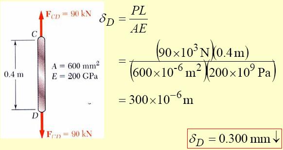
24 Evaluate total deflection, Stress & Strain Relationship Sample Problem The rigid bar BDE is supported by two links AB and CD. Link AB is made of aluminum ( E = 70 GPa) and has a cross- sectional area of 500 mm2. Link CD is made of steel ( E = 200 GPa) and has a cross- sectional area of ( 600 mm2). For the 30- kn force shown, determine the deflection a) of B, b) of D, and c) of E. SOLUTION: Apply a free- body analysis to the bar BDE to find the forces exerted by links AB and DC. Evaluate the deformation of links AB and DC or the displacements of B and D. Work out the geometry to find the deflection at E given the deflections at B and D. Free body: Bar BDE 6-11
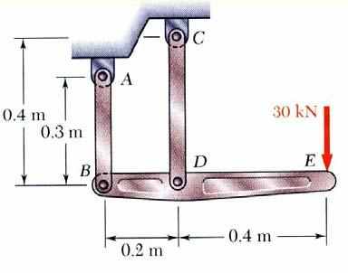
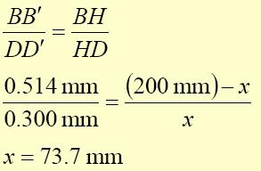
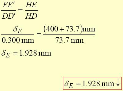
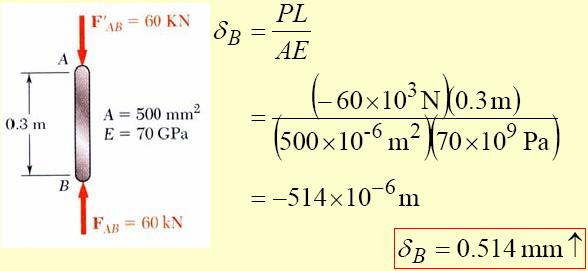
25 Displacement of B: Stress & Strain Relationship Displacement of D: Displacement of E: 7-11
26 Stress & Strain Relationship SOLVED PROBLEMS IN AXIAL DEFORMATION Problem No.1 A steel rod having a cross-sectional area of 300 mm2 and a length of 150 m is suspended vertically from one end. It supports a tensile load of 20 kn at the lower end. If the unit mass of steel is 7850 kg/m3 and E = MN/m2, find the total elongation of the rod. 8-11
27 Stress & Strain Relationship Problem No.2 A steel wire 30 ft long, hanging vertically, supports a load of 500 lb. Neglecting the weight of the wire, determine the required diameter if the stress is not to exceed 20 ksi and the total elongation is not to exceed 0.20 in. Assume E= psi. Problem No.3 An aluminum bar having a cross-sectional area of 0.5 in2 carries the axial loads applied at the positions shown in Figure beow. Compute the total change in length of the bar if E = psi. Assume the bar is suitably braced to prevent lateral buckling. 9-11
28 Stress & Strain Relationship Problem No.4 Solve Prob. No.3 if the points of application of the 6000-lb and the 4000-lb forces are interchanged

29 Stress & Strain Relationship Problem No.5 A bronze bar is fastened between a steel bar and an aluminum bar as shown in Figure below. Axial loads are applied at the positions indicated. Find the largest value of P that will not exceed an overall deformation of 3.0 mm, or the following stresses: 140 MPa in the steel, 120 MPa in the bronze, and 80 MPa in the aluminum. Assume that the assembly is suitably braced to prevent buckling. Use Est = 200 GPa, Eal = 70 GPa, and Ebr = 83 GPa

30 Lecture Notes: Dr. Hussam A. Mohammed Al- Mussiab Technical College Ferdinand P. Beer, E. Russell Johnston, Jr., and John T. DeWolf Stress and Strain Axial Loading Static Indeterminacy Structures for which internal forces and reactions cannot be determined from static s alone are said to be statically indeterminate. Deformations due to actual loads and redundant reactions are determined separately and then added or superposed. Redundant reactions are replaced with unknown loads which along with the other loads must produce compatible deformations. A structure will be statically indeterminate whenever it is held by more supports than are required to maintain its equilibrium. Example Determine the reactions at A and B for the steel bar and loading shown, assuming a close fit at both supports before the loads are applied. SOLUTION: Consider the reaction at B as redundant, release the bar from that support, and solve for the displacement at B due to the applied loads. Solve for the displacement at B due to the redundant reaction at B.


31 Stress & Strain Relationship Require that the displacements due to the loads and due to the redundant reaction be compatible, i. e., require that their sum be zero. Solve for the reaction at A due to applied loads and the reaction found at B. Solve for the displacement at B due to the applied loads with the redundant constraint released, Solve for the displacement at B due to the redundant constraint, 2-12


32 Require that the displacements due to the loads and due to the redundant reaction be compatible, Stress & Strain Relationship Find the reaction at A due to the loads and the reaction at B SOLVED PROBLEMS IN INDETERMINATE STRUCTURES Problem No.1 A steel bar 50 mm in diameter and 2 m long is surrounded by a shell of a cast iron 5 mm thick. Compute the load that will compress the combined bar a total of 0.8 mm in the length of 2 m. For steel, E = 200 GPa, and for cast iron, E = 100 GPa. 3-12
33 Stress & Strain Relationship Problem No.2 A reinforced concrete column 200 mm in diameter is designed to carry an axial compressive load of 300 kn. Determine the required area of the reinforcing steel if the allowable stresses are 6 MPa and 120 MPa for the concrete and steel, respectively. Use Eco = 14 GPa and Est = 200 GPa. 4-12

34 Problem No.3 A rigid block of mass M is supported by three symmetrically spaced rods as shown in figure. Each copper rod has an area of 900 mm2; E = 120 GPa; and the allowable stress is 70 MPa. The steel rod has an area of 1200 mm2; E = 200 GPa; and the allowable stress is 140 MPa. Determine the largest mass M which can be supported. Stress & Strain Relationship 5-12

35 Stress & Strain Relationship Problem No.3 The rigid platform in Figure shown has negligible mass and rests on two steel bars, each mm long. The center bar is aluminum and mm long. Compute the stress in the aluminum bar after the center load P = 400 kn has been applied. For each steel bar, the area is 1200 mm2 and E = 200 GPa. For the aluminum bar, the area is 2400 mm2 and E = 70 GPa. 6-12


36 Thermal Stresses A temperature change results in a change in length or thermal strain. There is no stress associated with the thermal strain unless the elongation is restrained by the supports. Treat the additional support as redundant and apply the principle of superposition. Stress & Strain Relationship The thermal deformation and the deformation from the redundant support must be compatible. SOLVED PROBLEMS IN THERMAL STRESSES Problem No.1 A steel rod with a cross-sectional area of 0.25 in2 is stretched between two fixed points. The tensile load at 70 F is 1200 lb. What will be the stress at 0 F? At what temperature will the stress be zero? Assume α = in / (in F) and E = psi. 7-12
37 Stress & Strain Relationship Problem No.2 A steel rod is stretched between two rigid walls and carries a tensile load of 5000 N at 20 C. If the allowable stress is not to exceed 130 MPa at -20 C, what is the minimum diameter of the rod? Assume α = 11.7 µm/(m C) and E = 200 GPa. Problem No.2 Steel railroad reels 10 m long are laid with a clearance of 3 mm at a temperature of 15 C. At what temperature will the rails just touch? What stress would be induced in the rails at that temperature if there were no initial clearance? Assume α = 11.7 µm/(m C) and E = 200 GPa. 8-12
38 Stress & Strain Relationship Problem No.3 A steel rod 3 feet long with a cross-sectional area of 0.25 in.2 is stretched between two fixed points. The tensile force is 1200 lb at 40 F. Using E = psi and α = in./(in. F), calculate (a) the temperature at which the stress in the bar will be 10 ksi; and (b) the temperature at which the stress will be zero. Problem No.4 A bronze bar 3 m long with a cross sectional area of 320 mm2 is placed between two rigid walls as shown in Figure. At a temperature of -20 C, the gap = 25 mm. Find the temperature at which the compressive stress in the bar will be 35 MPa. Use α = m/(m C) and E = 80 GPa. 9-12
, Poisson s ratio is defined as SOLVED PROBLEMS IN Poisson s Ratio Problem No.")
39 Stress & Strain Relationship Poisson s Ratio For a slender bar subjected to axial loading: The elongation in the x- direction is accompanied by a contraction in the other directions. Assuming that the material is isotropic ( no directional dependence), Poisson s ratio is defined as SOLVED PROBLEMS IN Poisson s Ratio Problem No.1 A solid cylinder of diameter d carries an axial load P. Show that its change in diameter is 4Pν / πed
40 Stress & Strain Relationship Problem No.2 A welded steel cylindrical drum made of a 10-mm plate has an internal diameter of 1.20 m. Compute the change in diameter that would be caused by an internal pressure of 1.5 MPa. Assume that Poisson's ratio is 0.30 and E = 200 GPa
41 Stress & Strain Relationship Problem No.2 A 2-in.-diameter steel tube with a wall thickness of 0.05 inch just fits in a rigid hole. Find the tangential stress if an axial compressive load of 3140 lb is applied. Assume ν = 0.30 and neglect the possibility of buckling. Problem No.3 A 150-mm-long bronze tube, closed at its ends, is 80 mm in diameter and has a wall thickness of 3 mm. It fits without clearance in an 80-mm hole in a rigid block. The tube is then subjected to an internal pressure of 4.00 MPa. Assuming ν = 1/3 and E = 83 GPa, determine the tangential stress in the tube

42 Lecture Notes: Dr. Hussam A. Mohammed Al- Mussiab Technical College Ferdinand P. Beer, E. Russell Johnston, Jr., and John T. DeWolf Torsion Torsional Loads on Circular Shafts Interested in stresses and strains of circular shafts subjected to twisting couples or torques Generator creates an equal and opposite torque T Shaft transmits the torque to the generator Turbine exerts torque T on the shaft Net Torque Due to Internal Stresses Net of the internal shearing stresses is an internal torque, equal and opposite to the applied torque, Although the net torque due to the shearing stresses is known, the distribution of the stresses is not Distribution of shearing stresses is statically indeterminate must consider shaft deformations Unlike the normal stress due to axial loads, the distribution of shearing stresses due to torsional loads can not be assumed uniform.


43 Torsion Axial Shear Components Torque applied to shaft produces shearing stresses on the faces perpendicular to the axis. Conditions of equilibrium require the existence of equal stresses on the faces of the two planes containing the axis of the shaft The existence of the axial shear components is demonstrated by considering a shaft made up of axial slats. The slats slide with respect to each other when equal and opposite torques are applied to the ends of the shaft. Shaft Deformations From observation, the angle of twist of the shaft is proportional to the applied torque and to the shaft length. When subjected to torsion, every cross- section of a circular shaft remains plane and undistorted. 2-10


44 Torsion Cross- sections for hollow and solid circular shafts remain plain and undistorted because a circular shaft is axisymmetric. Cross- sections of noncircular ( nonaxisymmetric) shafts are distorted when subjected to torsion. Shearing Strain Consider an interior section of the shaft. As a torsional load is applied, an element on the interior cylinder deforms into a rhombus. Since the ends of the element remain planar, the shear strain is equal to angle of twist. It follows that Shear strain is proportional to twist and radius 3-10


 the minimum and maximum shearing stress in shaft BC, ( b) the required diameter d")
45 Stresses in Elastic Range Multiplying the previous equation by the shear modulus, Torsion From Hooke s Law,, so The shearing stress varies linearly with the radial position in the section. Recall that the sum of the moments from the internal stress distribution is equal to the torque on the shaft at the section, The results are known as the elastic torsion formulas, Sample Problem Shaft BC is hollow with inner and outer diameters of 90 mm and 120 mm, respectively. Shafts AB and CD are solid of diameter d. For the loading shown, determine ( a) the minimum and maximum shearing stress in shaft BC, ( b) the required diameter d of shafts AB and CD if the allowable shearing stress in these shafts is 65 MPa. 4-10


46 Torsion SOLUTION: Cut sections through shafts AB and BC and perform static equilibrium analysis to find torque loadings Apply elastic torsion formulas to find minimum and maximum stress on shaft BC 5-10


47 Torsion Given allowable shearing stress and applied torque, invert the elastic torsion formula to find the required diameter Angle of Twist in Elastic Range Recall that the angle of twist and maximum shearing strain are related, In the elastic range, the shearing strain and shear are related by Hooke s Law, Equating the expressions for shearing strain and solving for the angle of twist, If the torsional loading or shaft crosssection changes along the length, the angle of rotation is found as the sum of segment rotations 6-10


48 Torsion Design of Transmission Shafts Principal transmission shaft performance specifications are: - power - speed Designer must select shaft material and cross- section to meet performance specifications without exceeding allowable shearing stress. Determine torque applied to shaft at specified power and speed, Find shaft cross- section which will not exceed the maximum allowable shearing stress, 7-10
49 SOLVED PROBLEMS IN TORSION Torsion Problem No.1 A steel shaft 3 ft long that has a diameter of 4 in. is subjected to a torque of 15 kip ft. Determine the maximum shearing stress and the angle of twist. Use G = psi. Problem No.2 What is the minimum diameter of a solid steel shaft that will not twist through more than 3 in a 6- m length when subjected to a torque of 12 kn m? What maximum shearing stress is developed? Use G = 83 GPa. Problem No.3 A steel marine propeller shaft 14 in. in diameter and 18 ft long is used to transmit 5000 hp at 189 rpm. If G = psi, determine the maximum shearing stress. 8-10
50 Torsion Problem No.4 A solid steel shaft 5 m long is stressed at 80 MPa when twisted through 4. Using G = 83 GPa, compute the shaft diameter. What power can be transmitted by the shaft at 20 Hz? 9-10
51 Torsion Problem No.5 A 2-in-diameter steel shaft rotates at 240 rpm. If the shearing stress is limited to 12 ksi, determine the maximum horsepower that can be transmitted. Problem No.6 A steel propeller shaft is to transmit 4.5 MW at 3 Hz without exceeding a shearing stress of 50 MPa or twisting through more than 1 in a length of 26 diameters. Compute the proper diameter if G = 83 GPa
52 Problem 310 Show that the hollow circular shaft whose inner diameter is half the outer diameter has a torsional strength equal to 15/16 of that of a solid shaft of the same outside diameter. Solution 310 Problem 311 An aluminum shaft with a constant diameter of 50 mm is loaded by torques applied to gears attached to it as shown in Fig. P-311. Using G = 28 GPa, determine the relative angle of twist of gear D relative to gear A.
53 Solution 311 Problem 312 A flexible shaft consists of a 0.20-in-diameter steel wire encased in a stationary tube that fits closely enough to impose a frictional torque of 0.50 lb in/in. Determine the maximum length of the shaft if the shearing stress is not to exceed 20 ksi. What will be the angular deformation of one end relative to the other end? G = psi. Solution 312
54 Problem 313 Determine the maximum torque that can be applied to a hollow circular steel shaft of 100-mm outside diameter and an 80-mm inside diameter without exceeding a shearing stress of 60 MPa or a twist of 0.5 deg/m. Use G = 83 GPa. Solution 313 Problem 314 The steel shaft shown in Fig. P-314 rotates at 4 Hz with 35 kw taken off at A, 20 kw removed at B, and 55 kw applied at C. Using G = 83 GPa, find the maximum shearing stress and the angle of rotation of gear A relative to gear C.
55 Solution 314 Problem 315 A 5-m steel shaft rotating at 2 Hz has 70 kw applied at a gear that is 2 m from the left end where 20 kw are removed. At the right end, 30 kw are removed and another 20 kw leaves the shaft at 1.5 m from the right end. (a) Find the uniform shaft diameter so that the shearing stress will not exceed 60 MPa. (b) If a uniform shaft diameter of 100 mm is specified, determine the angle by which one end of the shaft lags behind the other end. Use G = 83 GPa.
56 Solution 315

57 Lecture Notes: Dr. Hussam A. Mohammed Al- Mussiab Technical College Ferdinand P. Beer, E. Russell Johnston, Jr., and John T. DeWolf Pure Bending Pure Bending: Prismatic members subjected to equal and opposite couples acting in the same longitudinal plane

58 Pure Bending Other Loading Types Eccentric Loading: Axial loading which does not pass through section centroid produces internal forces equivalent to an axial force and a couple Transverse Loading: Concentrated or distributed transverse load produces internal forces equivalent to a shear force and a couple Principle of Superposition: The normal stress due to pure bending may be combined with the normal stress due to axial loading and shear stress due to shear loading to find the complete state of stress. Symmetric Member in Pure Bending Internal forces in any cross section are equivalent to a couple. The moment of the couple is the section bending moment. From statics, a couple M consists of two equal and opposite forces. The sum of the components of the forces in any direction is zero. The moment is the same about any axis perpendicular to the plane of the couple and zero about any axis contained in the plane. These requirements may be applied to the sums of the components and moments of the statically indeterminate elementary internal forces. 2-9


 above the neutral plane and positive")
59 Pure Bending Bending Deformations Beam with a plane of symmetry in pure bending: member remains symmetric bends uniformly to form a circular arc cross-sectional plane passes through arc center and remains planar length of top decreases and length of bottom increases a neutral surface must exist that is parallel to the upper and lower surfaces and for which the length does not change stresses and strains are negative (compressive) above the neutral plane and positive (tension) below it 3-9


60 Pure Bending Strain Due to Bending Consider a beam segment of length L. After deformation, the length of the neutral surface remains L. At other sections, 4-9


61 Stress Due to Bending For a linearly elastic material, Pure Bending For static equilibrium, First moment with respect to neutral plane is zero. Therefore, the neutral surface must pass through the section centroid. For static equilibrium, Beam Section Properties The maximum normal stress due to bending, 5-9


62 Pure Bending A beam section with a larger section modulus will have a lower maximum stress Consider a rectangular beam cross section, Between two beams with the same cross sectional area, the beam with the greater depth will be more effective in resisting bending. Structural steel beams are designed to have a large section modulus. Properties of American Standard Shapes 6-9


 the maximum tensile and")
63 Deformations in a Transverse Cross Section Deformation due to bending moment M is quantified by the curvature of the neutral surface Pure Bending Although cross sectional planes remain planar when subjected to bending moments, in-plane deformations are nonzero, Expansion above the neutral surface and contraction below it cause an in-plane curvature, Sample Problem A cast-iron machine part is acted upon by a 3 knm couple. Knowing E = 165GPa and neglecting the effects of fillets, determine (a) the maximum tensile and compressive stresses, (b) the radius of curvature. 7-9


64 Pure Bending SOLUTION: Based on the cross section geometry, calculate the location of the section centroid and moment of inertia. Apply the elastic flexural formula to find the maximum tensile and compressive stresses. 8-9


65 Pure Bending Calculate the curvature 9-9
MECHANICS OF MATERIALS
 Third E CHTER 1 Introduction MECHNICS OF MTERILS Ferdinand. Beer E. Russell Johnston, Jr. John T. DeWolf Lecture Notes: J. Walt Oler Texas Tech University Concept of Stress Contents Concept of Stress Review
Chapter 3: Torsion. Chapter 4: Shear and Moment Diagram. Chapter 5: Stresses In beams
 Chapter 3: Torsion Chapter 4: Shear and Moment Diagram Chapter 5: Stresses In beams Torsion Torsion or Torque, T, put simply, is referred to as a twisting moment. θ The derived formulas are: Where: Torsional
Question Paper Code : 11410
 Reg. No. : Question Paper Code : 11410 B.E./B.Tech. DEGREE EXAMINATION, APRIL/MAY 2011 Fourth Semester Mechanical Engineering ME 2254 STRENGTH OF MATERIALS (Common to Automobile Engineering and Production
Chapter 2: Strain. Chapter 3: Torsion. Chapter 4: Shear and Moment Diagram
 Chapter 2: Strain Chapter 3: Torsion Chapter 4: Shear and Moment Diagram Strain - Is defined as change in length per unit length, simply put it is unit deformation L Stress and Strain Exist concurrently
FE Review Mechanics of Materials
 1 2 3 4 5 6 7 8 9 10 11 12 13 14 15 16 17 18 19 20 21 22 23 24 25 26 27 28 29 1. T he element is subjected to the plane stress condition shown. a-x = - 140 M Pa a- y = 205 M Pa Txy = 100 M Pa What is t
1.Axial Force, Shear Force and Bending Moment:
 1 TRIBHUVAN UNIVERSITY INSTITUTE OF ENGINEERING PULCHOWK CAMPUS (Pulchowk, Lalitpur) Subject: Strength of Materials(II/I) (Tutorial ) 1.Axial Force, Shear Force and Bending Moment: 1. Draw AFD, SFD and
 VALLIAMMAI ENGINEERING COLLEGE DEPARTMENT OF MECHANICAL ENGINEERING QUESTION BANK CE 6306 - STRENGTH OF MATERIALS UNIT I STRESS STRAIN DEFORMATION OF SOLIDS PART- A (2 Marks) 1. What is Hooke s Law? 2.
Code No: R Set No. 1
 Code No: R05310305 Set No. 1 III B.Tech I Semester Regular Examinations, November 2007 DESIGN OF MACHINE MEMBERS-I ( Common to Mechanical Engineering and Production Engineering) Time: 3 hours Max Marks:
SIDDHARTH GROUP OF INSTITUTIONS :: PUTTUR Siddharth Nagar, Narayanavanam Road QUESTION BANK (DESCRIPTIVE)
") SIDDHARTH GROUP OF INSTITUTIONS :: PUTTUR Siddharth Nagar, Narayanavanam Road 517583 QUESTION BANK (DESCRIPTIVE) Subject with Code :Strength of Materials-II (16CE111) Course & Branch: B.Tech - CE Year
SIDDHARTH GROUP OF INSTITUTIONS :: PUTTUR Siddharth Nagar, Narayanavanam Road 517583 QUESTION BANK (DESCRIPTIVE) Subject with Code :Strength of Materials-II (16CE111) Course & Branch: B.Tech - CE Year
UNIT I SIMPLE STRESSES AND STRAINS, STRAIN ENERGY
 SIDDHARTH GROUP OF INSTITUTIONS :: PUTTUR Siddharth Nagar, Narayanavanam Road 517583 QUESTION BANK (DESCRIPTIVE) Subject with Code: Year & Sem: II-B.Tech & I-Sem Course & Branch: B.Tech - ME Regulation:
Subject with Code: Strength of Materials(16CE104) Course& Branch: B. Tech - CE Year &Sem : II-B. Tech &I-Sem Regulation: R16
 Course& Branch: B. Tech - CE Year &Sem : II-B. Tech &I-Sem Regulation: R16") SIDDHARTH INSTITUTE OF ENGINEERING &TECHNOLOGY:: PUTTUR (Approved by AICTE, New Delhi & Affiliated to JNTUA, Anantapuramu) (Accredited by NBA & Accredited by NAAC with A Grade) (An ISO 9001:2008 Certified
SIDDHARTH INSTITUTE OF ENGINEERING &TECHNOLOGY:: PUTTUR (Approved by AICTE, New Delhi & Affiliated to JNTUA, Anantapuramu) (Accredited by NBA & Accredited by NAAC with A Grade) (An ISO 9001:2008 Certified
MECHANICS OF SOLIDS IM LECTURE HOURS PER WEEK STATICS IM0232 DIFERENTIAL EQUAQTIONS
 COURSE CODE INTENSITY PRE-REQUISITE CO-REQUISITE CREDITS ACTUALIZATION DATE MECHANICS OF SOLIDS IM0233 3 LECTURE HOURS PER WEEK 48 HOURS CLASSROOM ON 16 WEEKS, 96 HOURS OF INDEPENDENT WORK STATICS IM0232
1. Name the various sources of stress concentration in machine elements.
 TWO MARKS QUESTIONS 1. Name the various sources of stress concentration in machine elements. 2. What is meant by resilience of a body? 3. What are the factors to be considered for the selection of materials
The designs, depending upon the methods used, may be classified as follows:
 Definition Machine Design is the creation of new and better machines and improving the existing ones. A new or better machine is one which is more economical in the overall cost of production and operation.
R13. II B. Tech I Semester Regular/Supplementary Examinations, Dec MECHANICS OF SOLIDS (Com. to ME, AME, AE, MTE) Time: 3 hours PART-A
 Time: 3 hours PART-A") SET - 1 II B. Tech I Semester Regular/Supplementary Examinations, Dec - 2015 MECHANICS OF SOLIDS (Com. to ME, AME, AE, MTE) Time: 3 hours Max. Marks: 70 Note: 1. Question Paper consists of two parts (Part-A
SET - 1 II B. Tech I Semester Regular/Supplementary Examinations, Dec - 2015 MECHANICS OF SOLIDS (Com. to ME, AME, AE, MTE) Time: 3 hours Max. Marks: 70 Note: 1. Question Paper consists of two parts (Part-A
Properties in Shear. Figure 7c. Figure 7b. Figure 7a
 Properties in Shear Shear stress plays important role in failure of ductile materials as they resist to normal stress by undergoing large plastic deformations, but actually fail by rupturing under shear
Page 1 of 46 Exam 1. Exam 1 Past Exam Problems without Solutions NAME: Given Formulae: Law of Cosines: C. Law of Sines:
 NAME: EXAM 1 PAST PROBLEMS WITHOUT SOLUTIONS 100 points Tuesday, September 26, 2017, 7pm to 9:30 You are allowed to use a calculator and drawing equipment, only. Formulae provided 2.5 hour time limit This
St.MARTIN S ENGINEERING COLLEGE
 St.MARTIN S ENGINEERING COLLEGE Dhulapally, Secunderabad-500 014 Subject: STRENGTH OF MATERIALS - II Class : Civil II Part-A (Short Answer Questions) UNIT-I 1 Define a) Torque b) Torsional moment of resistance
Code No: RR Set No. 1
 Code No: RR310305 Set No. 1 III B.Tech I Semester Supplementary Examinations, March 2006 DESIGN OF MACHINE MEMBERS-I ( Common to Mechanical Engineering and Production Engineering) Time: 3 hours Max Marks:
R10 Set No: 1. Design of Machine Members-I (Mechanical Engineering) Time: 3 Hours Max Marks: 75 ''' ' '' '' ''
 Time: 3 Hours Max Marks: 75 ''' ' '' '' ''") R10 Set No: 1 III B.Tech. I Semester Supplementary Examinations, June/July - 2014 Design of Machine Members-I (Mechanical Engineering) Time: 3 Hours Max Marks: 75 Answer any FIVE Questions All Questions
R10 Set No: 1 III B.Tech. I Semester Supplementary Examinations, June/July - 2014 Design of Machine Members-I (Mechanical Engineering) Time: 3 Hours Max Marks: 75 Answer any FIVE Questions All Questions
BEAMS: COMPOSITE BEAMS; STRESS CONCENTRATIONS
 BEAMS: COMPOSITE BEAMS; STRESS CONCENTRATIONS Slide No. 1 Bending of In the previous discussion, we have considered only those beams that are fabricated from a single material such as steel. However, in
LECTURE 25 and 26. Simple Bending Theory OR Theory of Flexure for Initially Straight Beams
 LECTURE 25 and 26 Simple Bending Theory OR Theory of Flexure for Initially Straight Beams (The normal stress due to bending are called flexure stresses) Preamble: When a beam having an arbitrary cross
5.4 Analysis for Torsion
 5.4 Analysis for Torsion This section covers the following topics. Stresses in an Uncracked Beam Crack Pattern Under Pure Torsion Components of Resistance for Pure Torsion Modes of Failure Effect of Prestressing
A Guide for the Interpretation of Structural Design Options for Residential Concrete Structures
 CFA Technical Note: 008-2010 A Guide for the Interpretation of Structural Design Options for Residential Concrete Structures CFA Technical This CFA Technical Note is intended to serve as a guide to assist
E APPENDIX. The following problems are intended for solution using finite element. Problems for Computer Solution E.1 CHAPTER 3
 E APPENDIX Problems for Computer Solution The following problems are intended for solution using finite element analysis software. In general, the problems associated with Chapters 3, 4, and 9 can be solved
Code No: R Set No. 1
 Code No: R059210303 Set No. 1 II B.Tech I Semester Regular Examinations, November 2006 MECHANICS OF SOLIDS ( Common to Mechanical Engineering, Mechatronics, Metallurgy & Material Technology, Production
10.5 ECCENTRICALLY LOADED COLUMNS: AXIAL LOAD AND BENDING.
 13 10.5 ECCENTRICALLY LOADED COLUMNS: AXIAL LOAD AND BENDING. Members that are axially, i.e., concentrically, compressed occur rarely, if ever, in buildings and other structures. Components such as columns
Level 6 Graduate Diploma in Engineering Structural analysis
 9210-111 Level 6 Graduate Diploma in Engineering Structural analysis Sample Paper You should have the following for this examination one answer book non-programmable calculator pen, pencil, ruler, drawing
Full file at
 ink full download: Solution Manual for Mechanics of Materials 7th Edition by eer Johnston DeWolf and Mazurek https://digitalcontentmarket.org/download/solution-manual-for-mechanics -of-materials-7th-edition-by-beer-johnston-dewolf-and-mazurek/
Estimate the endurance strength in MPa if the rod is used in rotating bending.
 348 Mechanical Engineering Design PROBLEMS Problems marked with an asterisk (*) are linked to problems in other chapters, as summarized in Table 1 1 of Sec. 1 16, p. 24. Problems 6 1 to 6 63 are to be
Conventional Paper II (a) Draw a crank rocker mechanism and identify all instantaneous centers.
 Draw a crank rocker mechanism and identify all instantaneous centers.") Conventional Paper II-2014 1. Answer of the following (Each part carries 4 marks): (a) Draw a crank rocker mechanism and identify all instantaneous centers. (b) A steel tube 2.5 cm external diameter and
Conventional Paper II-2014 1. Answer of the following (Each part carries 4 marks): (a) Draw a crank rocker mechanism and identify all instantaneous centers. (b) A steel tube 2.5 cm external diameter and
CITY AND GUILDS 9210 Unit 130 MECHANICS OF MACHINES AND STRENGTH OF MATERIALS OUTCOME 1 TUTORIAL 1 - BASIC STRESS AND STRAIN
 CITY AND GUILDS 910 Unit 130 MECHANICS O MACHINES AND STRENGTH O MATERIALS OUTCOME 1 TUTORIAL 1 - BASIC STRESS AND STRAIN Outcome 1 Explain static equilibrium, Newton's laws, and calculation of reaction
STRENGTH AND MECHANICS OF MATERIALS ME-303 VIVA QUESTIONS AND ANSWERS
 STRENGTH AND MECHANICS OF MATERIALS ME-303 VIVA QUESTIONS AND ANSWERS 1. Strain is defined as the ratio of (a) change in volume to original volume (b) change in length to original length (c) change in
Chapter Objectives. To show how to determine the forces in the members of a truss using: the method of joints and the method of sections.
 Structural Analysis Chapter Objectives To show how to determine the forces in the members of a truss using: the method of joints and the method of sections. Chapter Outline Two-force members Planar (Simple)
Chapter 4 MECHANICAL PROPERTIES OF MATERIAL. By: Ardiyansyah Syahrom
 Chapter 4 MECHANICAL PROPERTIES OF MATERIAL By: Ardiyansyah Syahrom Chapter 2 STRAIN Department of Applied Mechanics and Design Faculty of Mechanical Engineering Universiti Teknologi Malaysia 1 Expanding
Mechanical Engineering
 Mechanical Engineering Strength of Materials Comprehensive Theory with Solved Examples and Practice Questions Publications Publications MADE EASY Publications Corporate Office: 44-A/4, Kalu Sarai (Near
15.2 Approximate Analysis of a Continuous Beam for Gravity Load
 15.2 Approximate Analysis of a Continuous Beam for Gravity Load Figure 15.1 Location of points of inflection and shear and moment curves for beams with various idealized end conditions 1 15.2 Approximate
UNIT -2 (A) BENDING MOMENT AND SHEAR FORCE DIAGRAM FOR BEAMS. MYcsvtu Notes.
 BENDING MOMENT AND SHEAR FORCE DIAGRAM FOR BEAMS. MYcsvtu Notes.") UNIT -2 (A) BENDING MOMENT AND SHEAR FORCE DIAGRAM FOR BEAMS Beam It is a structural member whose longitudinal dimension is large compared to the transverse dimension. The beam is supported along its length
UNIT -2 (A) BENDING MOMENT AND SHEAR FORCE DIAGRAM FOR BEAMS Beam It is a structural member whose longitudinal dimension is large compared to the transverse dimension. The beam is supported along its length
DIN EN : (E)
") DIN EN 1999-1-1:2014-03 (E) Eurocode 9: Design of aluminium structures - Part 1-1: General structural rules Contents Page Foreword to EN 1999-1-1:2007... 7!Foreword to EN 1999-1-1:2007/A1:2009... 7 #Foreword
DIN EN 1999-1-1:2014-03 (E) Eurocode 9: Design of aluminium structures - Part 1-1: General structural rules Contents Page Foreword to EN 1999-1-1:2007... 7!Foreword to EN 1999-1-1:2007/A1:2009... 7 #Foreword
ST7008 PRESTRESSED CONCRETE
 ST7008 PRESTRESSED CONCRETE QUESTION BANK UNIT-I PRINCIPLES OF PRESTRESSING PART-A 1. Define modular ratio. 2. What is meant by creep coefficient? 3. Is the deflection control essential? Discuss. 4. Give
SPECIFICATIONS FOR THE CONSTRUCTION OF NEW PASSENGER EQUIPMENT CARS PREFACE
 SPECIFICATIONS FOR THE CONSTRUCTION OF NEW PASSENGER EQUIPMENT CARS Standard ADOPTED 1939; ADVANCED TO STANDARD, 1945. PREFACE The specifications have been prepared on the basis that they will be used
Fundamentals p. 1 Mechanical Engineering Design in Broad Perspective p. 3 An Overview of the Subject p. 3 Safety Considerations p.
 Fundamentals p. 1 Mechanical Engineering Design in Broad Perspective p. 3 An Overview of the Subject p. 3 Safety Considerations p. 5 Ecological Considerations p. 9 Societal Considerations p. 11 Overall
Gambit Centrum Oprogramowania i Szkoleń Sp. z o.o. Mathcad 14 Roark's Formulas for Stress and Strain
 Mathcad 14 Roark's Formulas for Stress and Strain Table of Contents About Mathcad E-Books Notes on the Organization and Special Features of Roark's Formulas for Stress and Strain Preface by Warren C. Young
When an axial load is applied to a bar, normal stresses are produced on a cross section perpendicular to the axis of the bar.
 11.1 AXIAL STRAIN When an axial load is applied to a bar, normal stresses are produced on a cross section perpendicular to the axis of the bar. In addition, the bar increases in length, as shown: 11.1
UNIT V PLASTIC ANALYSIS
 SIDDHARTH GROUP OF INSTITUTIONS :: PUTTUR Siddharth Nagar, Narayanavanam Road 517583 QUESTION BANK (DESCRIPTIVE) Subject with Code : SA-II (13A01505) Year & Sem: III-B.Tech & I-Sem Course & Branch: B.Tech
PRESTRESSED CONCRETE STRUCTURES. Amlan K. Sengupta, PhD PE Department of Civil Engineering Indian Institute of Technology Madras
 PRESTRESSED CONCRETE STRUCTURES Amlan K. Sengupta, PhD PE Department of Civil Engineering Indian Institute of Technology Madras Module 5: Analysis and Design for Shear and Torsion Lecture-23: Analysis
PORTAL FRAMES 1.0 INTRODUCTION
 36 PORTAL FRAMES 1.0 INTRODUCTION The basic structural form of portal frames was developed during the Second World War, driven by the need to achieve the low - cost building envelope. Now they are the
Rolling processes. Fig. (5-1)
") Page1 Rolling processes 5-1 introduction: Rolling is the process of reducing the thickness or changing the cross section of a long workpiece by compressive forces applied through a set of rolls, as shown
Page1 Rolling processes 5-1 introduction: Rolling is the process of reducing the thickness or changing the cross section of a long workpiece by compressive forces applied through a set of rolls, as shown
Dr. NAGY GYÖRGY Tamás Professor
 Dr. NAGY GYÖRGY Tamás Professor E mail: tamas.nagy gyorgy@upt.ro Tel: +40 256 403 935 Web: http://www.ct.upt.ro/users/tamasnagygyorgy/index.htm Office: A219 Dr.ing. Nagy György T. Faculty of Civil Engineering
 1.1. A solid circular post ABC (see figure) supports a load P 1 = 11.000 N acting at the top. A second load P 2 is uniformly distributed around the shelf at B. The diameters of the upper and lower parts
FME201 Solid & Structural Mechanics I Dr.Hussein Jama Office 414
 FME201 Solid & Structural Mechanics I Dr.Hussein Jama Hussein.jama@uobi.ac.ke Office 414 Lecture: Mon 11am -1pm (CELT) Tutorial Tue 12-1pm (E207) 10/1/2013 1 CHAPTER OBJECTIVES Show relationship of stress
Types of Strain. Engineering Strain: e = l l o. Shear Strain: γ = a b
 Types of Strain l a g Engineering Strain: l o l o l b e = l l o l o (a) (b) (c) Shear Strain: FIGURE 2.1 Types of strain. (a) Tensile. (b) Compressive. (c) Shear. All deformation processes in manufacturing
CE 221: MECHANICS OF SOLIDS I CHAPTER 3: MECHANICAL PROPERTIES OF MATERIALS
 CE 221: MECHANICS OF SOLIDS I CHAPTER 3: MECHANICAL PROPERTIES OF MATERIALS By Dr. Krisada Chaiyasarn Department of Civil Engineering, Faculty of Engineering Thammasat university Outline Tension and compression
EDEXCEL NATIONALS UNIT 18 ADVANCED MECHANICAL PRINCIPLES. ASSIGNMENT No. 1 - THE AFFECTS OF STRESS
 EDEXCEL NATIONALS UNIT 18 ADVANCED MECHANICAL PRINCIPLES ASSIGNMENT No. 1 - THE AFFECTS OF STRESS NAME: I agree to the assessment as contained in this assignment. I confirm that the work submitted is my
Fundamentals of Machine Component Design
 FOURTH E D I T I O N Fundamentals of Machine Component Design ROBERT C. JUVINALL Professor of Mechanical Engineering University of Michigan KURT M. MARSHEK Professor of Mechanical Engineering University
(a) Pin-Pin P cr = (b) Fixed-Fixed P cr = (d) Fixed-Pin P cr =
 Pin-Pin P cr = (b) Fixed-Fixed P cr = (d) Fixed-Pin P cr =") 1. The most critical consideration in the design of rolled steel columns carrying axial loads is the (a) Percent elongation at yield and the net cross-sectional area (b) Critical bending strength and axial
1. The most critical consideration in the design of rolled steel columns carrying axial loads is the (a) Percent elongation at yield and the net cross-sectional area (b) Critical bending strength and axial
Chapter Five Torsion. Reinforced Concrete Structures 2 (CEng-3122)
") Reinforced Concrete Structures 2 (CEng-3122) Chapter Five Torsion 1 School of Civil and Environmental Engineering Concrete Material and Structures Chair 2 1. Introduction 2. Torsional Resistance 3. Analysis
Reinforced Concrete Structures 2 (CEng-3122) Chapter Five Torsion 1 School of Civil and Environmental Engineering Concrete Material and Structures Chair 2 1. Introduction 2. Torsional Resistance 3. Analysis
ACCEPTANCE CRITERIA FOR HELICAL PILE SYSTEMS AND DEVICES PREFACE
 www.icc-es.org (800) 423-6587 (562) 699-0543 A Subsidiary of the International Code Council ACCEPTANCE CRITERIA FOR HELICAL PILE SYSTEMS AND DEVICES AC358 Approved June 2012 Compliance date December 1,
CADS A3D MAX. How to model shear walls
 CADS A3D MAX How to model shear walls Modelling shear walls in A3D MAX Introduction and synopsis This paper explains how to model shear walls in A3D MAX using the `wide column rigid arm sub-frame described
SET PROJECT STRUCTURAL ANALYSIS OF A TROUGH MODULE STRUCTURE, IN OPERATION AND EMERGENCY Luca Massidda
 SET PROJECT STRUCTURAL ANALYSIS OF A TROUGH MODULE STRUCTURE, IN OPERATION AND EMERGENCY Luca Massidda Table of Contents Introduction... 2 Finite element analysis... 3 Model description... 3 Mirrors...
Introduction to Structural Analysis TYPES OF STRUCTURES LOADS AND
 AND Introduction to Structural Analysis TYPES OF STRUCTURES LOADS INTRODUCTION What is the role of structural analysis in structural engineering projects? Structural engineering is the science and art
MAHALAKSHMI ENGINEERING COLLEGE TIRUCHIRAPALLI
 MAHALAKSHMI ENGINEERING COLLEGE TIRUCHIRAPALLI - 621213. QUESTION BANK WITH ANSWER DEPARTMENT: CIVIL SEMESTER: 06 SUBJECT CODE /NAME: CE 2352/DESIGN OF STEEL STRUCTURES YEAR: III UNIT II TENSION MEMBER
MECHANICAL PROPERTIES AND TESTS. Materials Science
 MECHANICAL PROPERTIES AND TESTS Materials Science Stress Stress is a measure of the intensity of the internal forces acting within a deformable body. Mathematically, it is a measure of the average force
Chapter 6: Structural Analysis
 Chapter 6: Structural Analysis Goals and Objectives Determine the forces in members of a truss using the method of joints Determine zero-force members Determine the forces in members of a truss using the
Fundamental Course in Mechanical Processing of Materials. Exercises
 Fundamental Course in Mechanical Processing of Materials Exercises 2017 3.2 Consider a material point subject to a plane stress state represented by the following stress tensor, Determine the principal
To have a clear idea about what really happened and to prevent the
 Failure Analysis on Skunk-Arm of Electrical Tower Failure Analysis on Skunk-Arm of Electrical Tower ABSTRACT Ahmad Rivai 1, Md Radzai Said 2 1, 2 Faculty of Mechanical Engineering, Universiti Teknikal
Shaikh sir s Reliance Academy Shahupuri Kolhapur. :::subject::: Strength of material. Question bank on Numerical problems
 1 Shaikh sir s Reliance Academy Shahupuri Kolhapur :::subject::: Strength of material Question bank on Numerical problems 2 No Chapter Type imp Note 1 1.Simple stresses Problem on simple stresses and strain
ARCH 331. Study Guide for Final Examination
 ARCH 331. Study Guide for Final Examination This guide is not providing answers for the conceptual questions. It is a list of topical concepts and their application you should be familiar with. It is an
When an axial load is applied to a bar, normal stresses are produced on a cross section perpendicular to the axis of the bar.
 11.1 AXIAL STRAIN When an axial load is applied to a bar, normal stresses are produced on a cross section perpendicular to the axis of the bar. In addition, the bar increases in length, as shown: 11.1
Chapter 6: Structural Analysis
 Chapter 6: Structural Analysis 1 6.1 Simple Trusses A truss is a structure composed of slender members joined together at their end points. The members commonly used in construction consist of wooden struts
VARIOUS TYPES OF SLABS
 VARIOUS TYPES OF SLABS 1 CHOICE OF TYPE OF SLAB FLOOR The choice of type of slab for a particular floor depends on many factors. Economy of construction is obviously an important consideration, but this
ES230 Strength of Materials Exam 6 - Compilation Prof. Kurtz, ES230 STRENGTH OF MATERIALS Exam 6 Wednesday, April 26, 2017, 7pm
 Given Formulae Bending M/EI = 1/ = -y/ =My/I = E Beam Shear Stress = VQ/It q = VQ/I q = F/s Torsion I = ( /4)r 4 for a solid, circular shape of radius r Pressure Vessels hoop = Pr/t long = Pr/2t ES230
ENGINEERING SOLID MECHANICS Fundamentals and Applications
 ENGINEERING SOLID MECHANICS Fundamentals and Applications Abdel-Rahman Ragab Salah Eldin Bayoumi CRC Press Boca Raton London New York Washington, D.C. Contents Chapter 1 Analysis of Stress 1.1 Rigid and
ME 207 Material Science I
 ME 207 Material Science I Chapter 4 Properties in Bending and Shear Dr. İbrahim H. Yılmaz http://web.adanabtu.edu.tr/iyilmaz Automotive Engineering Adana Science and Technology University Introduction
COLUMNS 1- Definition: The Egyptian code defines columns as : 2- Types of concrete columns
 COLUMNS 1- Definition: Columns are vertical compression members which carry primarily axial compression load; the axial load may be associated with bending moments in one or two directions, as shown in
Chapter 2: Mechanical Behavior of Materials
 Chapter : Mechanical Behavior of Materials Definition Mechanical behavior of a material relationship - its response (deformation) to an applied load or force Examples: strength, hardness, ductility, stiffness
ACCEPTANCE CRITERIA FOR HELICAL PILE SYSTEMS AND DEVICES PREFACE
 www.icc-es.org (800) 423-6587 (562) 699-0543 A Subsidiary of the International Code Council ACCEPTANCE CRITERIA FOR HELICAL PILE SYSTEMS AND DEVICES AC358 Approved June 2013 Compliance date December 1,
Ce 479 Reinforced Masonry Fall 2005
 INTRODUCTION TO STRUCTURAL DESIGN OF REINFORCED MASONRY In the preceding lecture on structural design of masonry, we have seen examples of unreinforced masonry bearing walls. In bearing walls, when the
Unit II Shear and Bending in Beams
 Beams and Bending Unit II Shear and Bending in Beams 2 Marks questions and answers 1. Mention the different types of supports. i. Roller support ii. Hinged support iii. Fixed support 2. Differentiate between
Contents FUNDAMENTALS OF STRUCTURAL ANALYSIS. Section A1 Elasticity... 3
 Preface... xv PART A FUNDAMENTALS OF STRUCTURAL ANALYSIS Section A1 Elasticity... 3 CHAPTER 1 Basic elasticity... 5 1.1 Stress... 5 1.2 Notation for forces and stresses... 7 1.3 Equations of equilibrium...
The problems in this guide are from past exams, 2011 to 2016.
 CE 311 Exam 1 Past Exam Problems, 2011 to 2016 Exam 1 (14% of the grade) THURSDY, 9/21 7 TO 9:30PM. OPTIONL Q& SESSION WED. 9/20, 8PM. COVERGE: LESSONS 1 TO 9 Exam is designed for 2 hours, but a maximum
SHRI RAMSWAROOP MEMORIAL COLLEGE OF ENGG. & MANAGEMENT
 Time: 1 Hour B.Tech. [SEM V (ME)] QUIZ TEST-1 MACHINE DESIGN-1 Note: Attempt all questions. Q1) Why is the necessity of having more than one theories of failure? Explain various theories of failure. [QNO.1]
Nafadi, Khalaf Alla, Lucier, Rizkalla, Zia and Klein BEHAVIOR AND DESIGN OF DIRECTLY LOADED LEDGES OF SHORT SPAN L- SHAPED BEAMS
 BEHAVIOR AND DESIGN OF DIRECTLY LOADED LEDGES OF SHORT SPAN L- SHAPED BEAMS Mohamed Nafadi, Omar Khalaf Alla, Gregory Lucier, Sami Rizkalla, Paul Zia, NC State University, Raleigh, NC and Gary Klein, Wiss,
CIVL 3121 Trusses - Introduction 1/8
 CIVL 3121 Trusses - Introduction 1/8 We will discuss the determinacy, stability, and analysis of three forms of statically determinate trusses: simple, compound, and complex. CIVL 3121 Trusses - Introduction
Seismic performance of New Steel Concrete Composite Beam-Columns
 Seismic performance of New Steel Concrete Composite Beam-Columns Toshiaki FUJIMOTO, Hiroshi KOMATSU, Tomoyuki SAKURADA & Noritaka MOROHASHI College of Industrial Technology, Nihon University, Japan SUMMARY:
Journal of Asian Scientific Research EVALUATION OF RECTANGULAR CONCRETE-FILLED STEEL-HOLLOW SECTION BEAM-COLUMNS
 Journal of Asian Scientific Research journal homepage: http://www.aessweb.com/journals/5003 EVALUATION OF RECTANGULAR CONCRETE-FILLED STEEL-HOLLOW SECTION BEAM-COLUMNS Kamyar Bagherinejad 1 ---- Emad Hosseinpour
STRENGTH OF MATERIALS laboratory manual
 STRENGTH OF MATERIALS laboratory manual By Prof. Shaikh Ibrahim Ismail M.H. Saboo Siddik College of Engineering, MUMBAI TABLE OF CONTENT Sr. No. Title of Experiment page no. 1. Study of Universal Testing
Lecture No.4 Pressure Vessels
 Lecture No.4 4.1 Introduction The pressure vessels (i.e. cylinders or tanks) are used to store fluids under pressure. The fluid being stored may undergo a change of state inside the pressure vessel as
Name of the Lab Course (Basic Structural Analysis Lab)
") Lebanese University Faculty of Engineering II LAB Civil Engineering Department Name of the Lab Course (Basic Structural Analysis Lab) Instructors: Wassim Elias, M2R. Civil Eng. Youssef Kassouf, Civil Eng.
Lebanese University Faculty of Engineering II LAB Civil Engineering Department Name of the Lab Course (Basic Structural Analysis Lab) Instructors: Wassim Elias, M2R. Civil Eng. Youssef Kassouf, Civil Eng.
How Beams Work, I. Statics and Strength of Materials
 How Beams Work, I Statics and Strength of Materials HOW BEAMS WORK Beams work by transferring transverse loads along their length to their supports primarily by resisting a force called internal bending
MECHANICS OF MATERIALS. Mechanical Properties of Materials
 MECHANICS OF MATERIALS Mechanical Properties of Materials By NUR FARHAYU ARIFFIN Faculty of Civil Engineering & Earth Resources Chapter Description Expected Outcomes Understand the concept of tension and
Residual Stresses and Distortion in Weldments
 Residual Stresses and Distortion in Weldments By: Aziz Shafiei Residual Stresses 1 Causes of Residual Stresses Residual stresses in metal structures occur for many reasons during various manufacturing
Design of Beam-Columns
 Design of Beam-Columns The below Figure shows examples of members subject to bending and axial force. The behaviour of such members results from the combination of both effects and varies with slenderness.
THE EFFECTS OF FRAME DEFORMATION ON WELDED GUSSET PLATES FOR DIAGONAL BRACING ELEMENTS LOADED IN TENSION
 Advanced Steel Construction Vol. 8, No. 4, pp. 398-421 (2012) 398 THE EFFECTS OF FRAME DEFORMATION ON WELDED GUSSET PLATES FOR DIAGONAL BRACING ELEMENTS LOADED IN TENSION J. Kent Hsiao 1,*, Donald W. Tempinson
Example of a modelling review Roof truss
 Example of a modelling review Roof truss Iain A MacLeod The Structure Figure gives an elevation and connection details for a roof truss. It is supported at each end on masonry walls. The trusses are at
Chapter 7: Mechanical Properties 1- Load 2- Deformation 3- Stress 4- Strain 5- Elastic behavior
 -1-2 -3-4 ( ) -5 ( ) -6-7 -8-9 -10-11 -12 ( ) Chapter 7: Mechanical Properties 1- Load 2- Deformation 3- Stress 4- Strain 5- Elastic behavior 6- Plastic behavior 7- Uniaxial tensile load 8- Bi-axial tensile
Network Arch Bridges. Presenter: Robert Salca technical support engineer, Midas UK
 Network Arch Bridges Presenter: Robert Salca technical support engineer, Midas UK In order to make sure that the sound system is working well a poll will appear shortly on your screens. Please vote by
Belleville Spring. The relation between the load F and the axial deflection y of each disc. Maximum stress induced at the inner edge
 Belleville Spring Disc spring, also called Belleville spring are used where high capacity compression springs must fit into small spaces. Each spring consists of several annular discs that are dished to
Mechanical behavior of crystalline materials- Comprehensive Behaviour
 Mechanical behavior of crystalline materials- Comprehensive Behaviour In the previous lecture we have considered the behavior of engineering materials under uniaxial tensile loading. In this lecture we
CHAPTER 2. Design Formulae for Bending
 CHAPTER 2 Design Formulae for Bending Learning Objectives Appreciate the stress-strain properties of concrete and steel for R.C. design Appreciate the derivation of the design formulae for bending Apply