County of Yolo Improvement Standards. Department of Planning and Public Works 292 West Beamer Street Woodland, CA 95695
|
|
|
- Winfred Stanley
- 5 years ago
- Views:
Transcription
1 County of Yolo Improvement Standards Department of Planning and Public Works 292 West Beamer Street Woodland, CA August 5, 2008
2 Addenda and Updates ADDENDA AND UPDATES DATE LOCATION AND DESCRIPTION OF REVISED SHEETS 06/01/2009 Unistrut tubing used to extend 30 below ground level. Per this revision it is embedded 6 to 8 into anchor. Dwg #4-28, Sheet 3 was added to summarize the sign standard. 12/16/ Sign Detail Revised 03/09/2010 Section 4 and Section 9 revised Sign Detail Revised 05/09/2011 Section 4 revised. Clarified pavement design life, added pavement marking standard Section 9 revised. Revised minimum gutter slope to /9/ Sign Detail Revised 5/6/2013 Sections 2, 3, and 9 revised 3-2 Signature Blocks detail revised 4-28 Road Sign detail revised 1/20/2017 Sections 2, 4, 5, and 10 revised 4-17 Trenching detail revised Telecommunications details added to Section Valve box detail revised i January 20, 2017
3 County of Yolo 1 Purpose and Definitions 2 General Requirements 3 Improvement Plan Requirements 4 Transportation Improvement Standards 5 Street Lighting 6 Sound Barrier and Security Walls 7 Sanitary Sewers 8 Water Systems 9 Storm Drainage 10 Grading 11 Stormwater Quality, Erosion and Sediment Control August Survey Monuments
4 Section 1 Purpose and Definitions SECTION 1 PURPOSE AND DEFINITIONS CONTENTS Page 1-1 Purpose Standard Update Referenced Standards Standard Forms Intended Use Technical Specifications Construction Contractor Addenda or Future Updates Omissions Definitions Page 1-i August 5, 2008
5 Section 1 Purpose and Definitions 1-1 PURPOSE SECTION 1 PURPOSE AND DEFINITIONS These Improvement Standards provide minimum standards for improvements to be built within County rights of way or easements, and private works that may be required as a condition for any entitlement granted by the County under Title 8 of the Yolo County Code. In particular these Improvement Standards are intended to serve as the County Standards referenced in Title 8, Chapter 1, Article 7. Design Standards of the Yolo County Code, which states To ensure that land development shall reflect the best interests of the people of the County, all developments pursuant to the provisions of this chapter and all improvements installed in, over, or under any existing or proposed right-of-way, easement, or parcel of real property of the County in satisfaction of a condition of a variance or use permit issued pursuant to the zoning regulations (Chapter 2 of this title), or required by order of the Board of Supervisors made in a proceeding for amending said zoning regulations by changing the boundaries of any zone, or required in connection with the issuance of a building permit, shall conform to the standards of design of this chapter and the County Standards as set forth by resolution of the Board of Supervisors. ( 6.40, Ord. 546, as amended by 1 and 3, Ord. 617) Project-specific conditions of approval or mitigation monitoring and reporting program requirements approved by the Board of Supervisors may result in more stringent requirements than provided for in these Improvement Standards. These Standards are necessary to provide for coordinated development of required facilities to be used by the public. These Standards shall serve to regulate and guide the design, preparation of plans, construction, repair, and alteration of: streets, highways, alleys, site access, storm drainage, sewerage, water supply facilities, street lighting and related public improvements, and set guidelines for similar private works. These Standards do not apply to improvements to be dedicated to, and maintained by jurisdictions with their own standards including any Community Service District, City, State, or other governmental entity. 1-2 STANDARDS UPDATE These Improvement Standards replace the Yolo County Improvement Standards and Specifications dated February REFERENCED STANDARDS These standards reference the Caltrans Standard Specifications, latest edition, and Caltrans Standard Plans for Construction of Local Streets and Roads, Caltrans Highway Design Manual, and Caltrans Traffic Manual, latest editions, the Standard Plans for Public Works Construction ( Greenbook, published by BNi Building News), and the American Association of State Highway and Transportation officials (AASHTO) A Policy on Geometric Design of Highways and Streets latest edition. Caltrans documents can be downloaded from the Engineering Service Center web site at STANDARD FORMS Standard forms are provided for reference and use by Department staff, Consultants and Developers. Many of these forms will require editing based on project specific requirements. 1-5 INTENDED USE These Improvement Standards are intended to provide minimum standards. The appropriate use of these Standards is the responsibility of the registered engineer in responsible charge of the design. Nothing in Page 1-1 August 5, 2008
6 Section 1 Purpose and Definitions these Standards is intended to relieve the Developer or Design Engineer from the responsibility for providing a complete design, or specifying more stringent requirements when site conditions warrant. At the County Engineer s discretion, these Standards may be modified if the Standards do not appear to be in the County s best interest. On a case-by-case basis, and for sound engineering reasons, minor modifications may be made to these Standards. In all such cases, the County Engineer shall approve any such variations from these Standards. 1-6 TECHNICAL SPECIFICATIONS The portions of these Standards that define the materials, work methods, quality and quantity for construction of any publicly maintained improvements shall apply to all construction contracts whether public or private. Public contracts include contracts typically between the County of Yolo and a construction contractor. Private contracts include contracts typically between a private party, such as a Developer, Land Owner, Home Owner, etc., and a construction contractor. 1-7 CONSTRUCTION CONTRACTOR All contractors performing work on improvements to be reviewed and approved for acceptance and maintenance by the County of Yolo, shall be constructed by Contractor(s) duly licensed, bonded and insured in accordance with the laws of the State of California and County requirements. 1-8 ADDENDA OR FUTURE UPDATES Future addenda or updates to these Standards will be noted in the Addenda and Updates sheet preceding this Section. The Improvement Standards on the County s website will be periodically updated, or new hard copies can be purchased directly from the Department. 1-9 OMISSIONS Any items or situations not included in these Improvement Standards shall be designed in accordance with general standard of care for engineering practice, as approved by the County Engineer. The following may be used as guidelines: Standard Plans for Public Works Construction ( Greenbook ), the Caltrans "Highway Design Manual, the Caltrans Standard Plans for Construction of Local Streets and Roads, and Caltrans "Traffic Manual, latest editions DEFINITIONS When the following terms or titles are used in these Standards or in any document or instrument where these Standards govern, the intent and meaning shall be as herein defined: A. Board Shall mean the Yolo County Board of Supervisors. B. Caltrans (or State) Standard Plans or Caltrans Standard Specifications Shall mean the Standard Specifications and Standard Plans of the State of California, Department of Transportation, latest edition. C. Design Engineer Shall mean any person or persons, firm, partnerships or corporation legally authorized to practice civil, mechanical or electrical engineering in the State of California as set forth in Section 6700 et. Seq. of the Business and Professions Code of the State (Professional Engineers Act) who prepares or submits improvements plan and specifications to the Department for approval. Page 1-2 August 5, 2008
7 Section 1 Purpose and Definitions D. County Code Shall mean the Yolo County Code as adopted and periodically updated by the Board of Supervisors. The Yolo County Code is available online at the County website. E. County Engineer An engineer designated by the Director to act as County s plan approval agent who is legally authorized to practice civil engineering in the State of California as set forth in Section 6700 et. Seq. of the Business and Professions Code of the State. (Professional Engineers Act) F. Department shall mean the County of Yolo, Department of Planning and Public Works, including wherever used in reference specifications or plans. G. Developer Shall mean any person or persons, firms, partnership, corporation or, combination thereof, financially responsible for the work involved. H. Development Shall mean the act, process, or result of any land division, land grading, utility installation, street or building construction on property. I. Digital Submittals or Electronic Files Shall mean data files prepared using appropriate software saved and transmitted in their native format for Department use and records. J. Director Shall mean the Director of the Department of Planning and Public Works acting either directly or through an authorized representative. K. Greenbook Standard Specifications and Standard Plans Shall mean Standard Specifications, latest edition, and Standard Plans for Public Works Construction, latest edition, written by Public Works Standards, Inc., published by BNi Building News. L. Inspector Shall mean the County s field representative observing the Developer s construction activities. M. Laboratory Shall mean a Caltrans-certified testing agency or testing firm that has been approved by the Planning and Public Works Department to perform quality control testing of construction performed in the County right of way. N. Mitigation Monitoring and Reporting Program (MMRP) An environmental mitigation program administered by the Department in accordance with County Code or Conditions of Approval adopted by the Yolo County Board of Supervisors. O. Public Works Agency Shall mean the Department of Planning and Public Works of the County of Yolo. P. Special District or Community Service District Shall mean a district formed for the purposes of providing public services as defined in the formation documents, which may include, but are not limited to sewer, water, storm drainage, fire, and street lighting services, and governed by an independent Board of Directors. Q. Standard Construction Specifications Shall mean the latest of the Greenbook Standard Specifications (latest edition), and as modified, governing the construction of roads, streets, sanitary sewers, storm drainage, concrete structures, water supply, traffic signals, street lighting and other facilities within the County of Yolo to be accepted by the Department or other Agency for maintenance or operation; also including private grading, erosion control, drainage, and landscaping. Page 1-3 August 5, 2008
8 Section 1 Purpose and Definitions R. Standard Drawings Shall mean the standard drawings included in these Design Standards and the referenced Standard Plans for other details not included herein. S. State As used in the State Specifications, shall mean County of Yolo. T. Urban Area Shall mean any area planned for urban development by the appropriate General Plan. Page 1-4 August 5, 2008
9 Section 2 General Requirements SECTION 2 GENERAL REQUIREMENTS CONTENTS Page 2-1 Engineer Required Plans Required Reference To County Improvement Standards Work In County Rights Of Way, Easements And Waterways Initial Plan Submittal Requirements Improvement Plans Resubmittal Plan Check And Inspection Fee Plans Approval Approved Plans Required Subdivision Improvement Agreement Required Improvement Plans Revisions During Construction Record Plans Conflicts, Error And Omissions Change In Design Engineer Special District Improvements And Submittals Special District Annexation Boring And Jacking Safety Requirements Existing Utilities Partial Plans Inspection Requirements Acceptance of Improvements Page 2-i January 20, 2017
10 Section 2 - General Requirements SECTION 2 GENERAL REQUIREMENTS 2-1 ENGINEER REQUIRED A Design Engineer shall prepare all plans and specifications for engineering works requiring County approval or permits. All design work shall be performed in accordance with these Improvement Standards and in accordance with the standard of practice for the particular branch of engineering. Pursuant to the California Business and Professions Code, Sections 6746 and 6747, improvement plans for work performed by communications companies or public utilities under the jurisdiction of the California Public Utilities Commission are not required to be prepared by a Design Engineer. 2-2 PLANS REQUIRED Complete plans for all proposed streets, highways, bikeways, alleys, site access, grading, earthwork, erosion control, storm drainage facilities, sewer collection, treatment and disposal facilities, water supply and distribution systems, street lighting, traffic control devices, underground utilities, landscaping, and any other improvement required by the project approvals, including any necessary design calculations, reports, dedications, and easements, shall be prepared by the Developer and submitted to the Department for approval. Exceptions may be made for minor work such as replacing infrastructure, connections to existing utilities, and related utility work, as determined by the County Engineer. 2-3 REFERENCE TO COUNTY IMPROVEMENT STANDARDS The General Notes of all plans shall include the following note: Unless shown or specified otherwise, all construction and materials shall comply with the latest edition of the Yolo County Improvement Standards. The Design Engineer shall be responsible for providing specific references on the plans to other standard specifications for construction features that are not included in these Improvement Standards. 2-4 WORK IN COUNTY RIGHTS OF WAY, EASEMENTS AND WATERWAYS The following are required prior to working within County rights-of-ways and easements: A. Possession of a complete set of Department approved improvement plans shall be required prior to performing work in Yolo County rights of way and easements. B. A valid encroachment permit issued by the Department shall be required prior to performing work in Yolo County rights of way as provided for in the California Streets and Highways Code, Section 1460 et. Seq., unless such work is performed under a Subdivision Agreement with the County as defined in Section of the Yolo County Code. C. The work shall be secured with a bond or other security, as required by Sections and (a) of the Yolo County Code. 2-5 INITIAL PLAN SUBMITTAL REQUIREMENTS The initial submittal of improvement plans shall be made to the Department. The initial submittal shall consist of the following, but is not be limited to: Page 2-1 January 20, 2017
11 Section 2 General Requirements A. Payment of deposit toward the actual cost of plan review as required by the Master Fee Resolution, and submittal of the necessary application to establish a reimbursable work order. B. The names, addresses and telephone numbers of the Developer and the Design Engineer. C. One copy of the final Conditions of Approval, including the Tentative Map and accompanying items as listed in the Yolo County Code and the Master Checklist for Final Map, Parcel Map, and Improvement Plan Submittals. D. One copy of the mitigation measures for the Development, including related maps and plans, and any other discretionary planning actions for the subject site and development. E. Three sets of plans and project specifications, complete and in accordance with these Improvement Standards. F. Supporting design studies, reports, calculations, plans, computations, and test data. a. Hydrology and Hydraulics calculations and reports for Storm Runoff, including watershed map. b. Sewer System Calculations and shed map. c. Water System Network Analysis and maps. d. Geotechnical Report describing subsurface condition, soil bearing capacity, groundwater levels, soil drainage characteristics, soil erodability characteristics, and containing recommendations for earth grading and compaction, road structural design based on R- value tests, boring logs, soil corrosivity, ground water, etc., as required to meet project needs and conditions. Additional information may be required by the Chief Building Official. e. Street Lighting System Design. f. Other material requested by the County Engineer. G. Cost estimates for all onsite and offsite improvements for the purpose of determining the amount of the Improvement Security. Cost estimates shall be based on the costs of construction as would be incurred by the County in the public bidding process, and shall include a minimum 15% construction cost contingency, and a minimum 20% allowance for project administration costs. (Final cost estimates sealed by Design Engineer shall be reviewed by the County Engineer prior to the approval of a Parcel or Final Map.) H. Parcel or Final Map submittal and accompanying items to be reviewed concurrently by the County Surveyor. I. Copy of utility letters in accordance with Section a. Joint Trench Plans must be submitted prior to approval of Improvement Plans and/or recordation of a related Map. b. All joint trenches designed and installed by the Developer shall include spare conduit(s) (e.g., for fiber optic or other telecommunication lines) and appurtenances as required by Page 2-2 January 20, 2017
12 Section 2 General Requirements the Yolo County General Services Department, and be installed to General Services Department Standards and Section 5. These spare conduit(s) and associated facilities shall be owned, operated, and maintained by the Yolo County General Services Department. J. Copies of permits as required by other agencies. K. Digital files as requested during plan review process. Digital files for all plans, maps, and other supporting documents required prior to final approval. L. Copies of rights-of-entry from adjacent properties required for access or construction activities. Additional copies of any submitted items shall be provided as requested by the Department. Should there be required alterations or revisions to the plans as submitted, the County Engineer will return one copy with the corrections marked or indicated thereon. If the plans submitted are not prepared in accordance with these Improvement Standards or are not in keeping with the standards of the profession, the County Engineer may return them unmarked and unapproved. 2-6 IMPROVEMENT PLANS RESUBMITTAL The County Engineer shall indicate the number of plan sets to be resubmitted. The Design Engineer shall notify the County Engineer in writing if plans being resubmitted contain revisions or alterations other than those required by the County Engineer on prior plan reviews. Revision notations shall not be shown on plans for revisions made prior to the County Engineer s approval of the plans. 2-7 PLAN CHECK AND INSPECTION FEE The required plan check fees and inspection fees shall be determined in accordance with the Yolo County Master Fee Resolution. Should the development not be carried to completion, any portion of the required deposit over and above the accumulated costs expended by the Department on the development will be refunded to the Developer. Failure of a Developer to complete a project does not relieve the Developer from being responsible for all costs incurred by the County. The Developer is responsible for notifying the Department of any change of billing address, ownership or design consultants. 2-8 PLANS APPROVAL Plans shall not be considered approved, nor shall construction be authorized, until the County Engineer signifies plan approval by signing every sheet of the set of plans. The County Engineer will sign the plans after the Design Engineer has made all the necessary revisions, signed and stamped the original plans, fees have been paid and any other related project requirements, such as, but not limited to, conditions of approval, have been fulfilled. For a Final Map or Parcel Map that requires Improvement Plans approval, the approval process will generally consist of the following: A. Final Map, Improvement Plans and supporting documentation are submitted to the Department for review. B. Comments are returned to the Developer or Design Engineer. Page 2-3 January 20, 2017
13 Section 2 General Requirements C. Corrected documents are re-submitted to the Department. This step and the previous one are repeated until the Map, Plans, and supporting documentation meet County requirements. D. The Department prepares the Subdivision Agreement for review by the Developer. Developer returns comments and Department revises as appropriate, in consultation with County Counsel. E. Developer submits final corrected Improvement Plans and Final Map to Department for County Engineer s approval and County Surveyor s approval, respectively. Developer submits executed Subdivision Agreement, including improvement security and material payment security, insurance certificates, fees, deeds, etc. F. Providing all Conditions of Approval for the Final Map have been satisfied by the Developer, the Department prepares agenda item for a subsequent Board of Supervisors meeting, to present the Improvement Plans, Final Map, and Subdivision Agreement to the Board of Supervisors. G. If the Board of Supervisors approves the agenda item, a copy of the approved Plans are released to Developer (signed originals remain with the County), the Map is signed by the County Surveyor and Director, forwarded to the Recorder, and the Agreement is executed. A grading permit may be issued following Board of Supervisors approval. H. Developer schedules pre-construction meeting with Department staff, other Agency staff, utility staff, Developer s Contractor, material testing lab, consultants and other appropriate personnel representing the Developer during construction. I. Construction on the site may begin following the pre-construction meeting. J. Developer and County hold periodic meetings to discuss and resolve any issues arising during construction. The County Engineer's plan approval is valid for a period of twelve months. Should Board of Supervisors approval not be obtained within a 12-month period, or, in the case of work not requiring Board of Supervisors approval, the work does not commence within a 12-month period, the plans shall be resubmitted for re-approval. 2-9 APPROVED PLANS REQUIRED The Developer shall provide the Contractor with properly approved plans. The County Engineer shall have the authority to order any Contractor to cease work on any project if said Contractor does not have properly approved plans in their possession. The cost of additional copies or reduced copies of approved plans that may be required by the County shall be provided at the Developer s cost SUBDIVISION IMPROVEMENT AGREEMENT REQUIRED Concurrently with the Board of Supervisors acceptance of the final map, the Developer shall enter into an agreement with the County agreeing to complete the public improvements within the time specified in the agreement. Such agreement shall provide a clause guaranteeing the workmanship and materials provided in all improvements for a twelve (12) months period after acceptance of the improvements by the Board of Supervisors. To assure that the improvements required by the County Code, these Improvement Standards, and the approved improvement plans are satisfactorily completed, the subdivision improvement agreement shall be accompanied by improvement securities furnished by the Developer for the cost of the improvements. Such securities shall include a Performance Bond in the amount of one hundred percent (100%) of the Page 2-4 January 20, 2017
14 Section 2 General Requirements engineer s estimate as approved by the County Engineer, and a Labor and Materials Payment Bond in the amount of one hundred percent (100%) of the engineer s estimate. Prior to acceptance of the improvements by the Board of Supervisors, the Developer shall furnish a warranty bond not less than fifteen (15%) percent of the engineer s estimated cost of the public improvements IMPROVEMENT PLANS REVISIONS DURING CONSTRUCTION Should changes become necessary during construction, the Developer shall first obtain the consent of the County Engineer and shall then resubmit the title sheet and the plan sheets affected for approval. The changes on the plans shall be made in the following manner: A. The original design shall not be eradicated from the plans but shall be lined out. B. In the event that eradicating the original design is necessary to maintain clarity of the plans, approval must first be obtained from the County Engineer. C. The changes shall be clearly shown on the plans with the changes and approval noted on the revision signature block, conforming to Standard Drawing 3-l. D. The changes shall be identified by the revision number in a triangle delineated on the plans adjacent to the change and on the revision signature block. Minor changes that do not affect the basic design may be made upon the written authorization of the County Engineer, but said changes must be shown on record plans when the contract is completed. The County Engineer may specify changes to the plans required to complete the necessary facilities, to be completed by the Developer. Changes to the plans ordered by the County Engineer shall conform to all of the above RECORD PLANS The Developer shall be responsible for keeping accurate records of all deviations from the plans. These records shall be utilized along with the Inspector s records to prepare a complete and accurate set of Record Plans ( As-Builts ). Field measurement and certification by the Design Engineer of all final grades shown on the improvement plans, including the finished pad elevations of subdivision lots, inverts, rims, grates, top of curb at changes in vertical alignment, toe and top of slope on all finished storm drain detention basins, and any other designed and constructed parameters as required by the County Engineer, shall be required prior to final acceptance of the subdivision improvements. Building pad elevations shall be constructed to within 0.2 foot of their elevation indicated on the approved plans, and all other improvements shall be constructed to within 0.1 foot of their elevation indicated on the approved plans. Certification shall comply with Section Constructed slopes of flowlines for pipes, channels and gutters shall not be less than 95% of the slope specified on the approved plans. Before final acceptance of the completed improvements, the Developer shall submit one bond, 24 x36, copy of the Record Plans to the County Engineer. Following review of the copy of the Record Plans by the County Engineer, final Record Plans shall be submitted to the Department on 24 x 36 polyester film sheets (Mylar, or equivalent) with matte finish. Page 2-5 January 20, 2017
15 Section 2 General Requirements 2-13 CONFLICTS, ERRORS AND OMISSIONS Excepted from the County Engineer s Improvement Plan approval are any features of the plans that are contrary to, in conflict with, or do not conform to, any California State Law, County Code or Resolution, conditions of approval, or generally accepted good engineering practice, in keeping with the standards of the engineering profession, even though such errors, omissions or conflicts may have been overlooked in the Department's review of the plans CHANGE IN DESIGN ENGINEER If the Developer elects to have a registered civil engineer or licensed land surveyor, other than the Design Engineer who prepared the plans, provide the construction staking, he shall provide the County Engineer in writing the name of the individual or firm one week prior to the staking of the project for construction. The Developer shall in all cases be responsible for: Verifying all construction, Preparation of revised plans for construction changes, Preparation of "as built" record plans upon completion of the construction. In the Developer's notification of a change in the firm providing construction staking, he shall acknowledge that he accepts responsibility for design changes and "as built" information as noted above SPECIAL DISTRICT APPROVALS AND SUBMITTALS The Department shall also review, although not approve, Special District facilities and improvements shown on related submittals to the County. All Special District improvements shall comply with these Standards, unless the District has adopted their own standards. A Special District shall approve plans for their respective portions of the improvements prior to County approval of the plan set. The Fire District shall approve plans showing the domestic water system improvements prior to County approval of the plan set. The Developer is responsible for coordinating submittals to Special Districts as required to obtain the necessary approvals, prior to County approval SPECIAL DISTRICT ANNEXATION Any development within the sphere of influence of, or intended to be served by, a Special District shall be annexed to that District prior to the approval of Improvement Plans for any facilities to be maintained and operated by the District. Contact the Yolo County Local Agency Formation Commission for annexation procedures. The Developer shall provide evidence of annexation to the Department BORING AND JACKING SAFETY REQUIREMENTS Any boring or jacking operation involving an opening greater than 30 inches in diameter is subject to the State of California Division of Industrial Safety's tunnel safety requirements. The Design Engineer shall submit to the State Division of Industrial Safety plans and specifications applicable to the tunnel operation, with a letter requesting tunnel classification, prior to bidding the project. The letter should identify the Department responsible for the project, and the Department's mailing address. The plans Page 2-6 January 20, 2017
16 Section 2 General Requirements shall identify underground utilities and tanks or areas for storing fuel and toxic gases in the vicinity of the tunnel site, and a description of the historical land use in the area. The request for classification should be submitted allowing ample time for the Division of Industrial Safety review in order that any special requirements can be included in the project plans and specifications EXISTING UTILITIES All existing utilities are to be shown on the plans. The Design Engineer shall submit prints of the preliminary and approved plans to the utility companies involved. Copies of the transmittal letters to the utility companies shall be provided to the County Engineer. The Developer shall make necessary arrangements with the serving utilities to properly plan for any relocation and undergrounding of existing utilities, and for the required expansion to serve the development. All existing overhead utilities adjacent to, or in, a Development shall be placed underground. All utility services within a Development shall be placed underground PARTIAL PLANS Where the improvement plans submitted cover only a portion of ultimate development, the plans submitted shall be accompanied by the approved plans of the ultimate development. The approved plans shall show topographic features of the ultimate development at an adequate scale to clearly show the proposed improvements INSPECTION REQUIREMENTS Any public improvements which will be maintained by the County, or which are constructed within a County right of way or easement, shall be inspected during construction by the County Engineer, or designee. Each phase of construction shall be inspected and approved by the County Engineer prior to proceeding to subsequent phases. The Developer shall be responsible for the cost of the services of a materials testing laboratory as defined in Section 1-10M. Inspection shall include a materials and field testing program to document compliance with the approved Plans. The scope and frequency of testing shall be determined by the County Engineer, but at a minimum shall comply with Table 1. Table 1 - CONSTRUCTION QUALITY ASSURANCE TESTING ITEM TYPE OF TEST FREQUENCY Trench backfill Subgrades ASTM D1557 Moisture/density curve ASTM D1557 Relative Compaction ASTM D1557 Moisture/density curve ASTM D1557 Compaction Proof roll One per soil type encountered. Field tests: Each lift: every 200 square feet, at each lateral, and 3 per intersection. One per soil type encountered. Field tests: Each lift: every 2400 sq. feet. Prior to paving with fully loaded, 3 axle, water truck, 4000 gallon minimum Page 2-7 January 20, 2017
17 Section 2 General Requirements Aggregate Bases Asphalt Concrete ASTM C136-Sieve Tests ASTM D1557-Moisture/density curve ASTM D1557- Relative Compaction Proof roll CTM 375 In-Place Density ASTM D1557 Temperature Lift thickness Cross slope Smoothness One per source material One per source material Field tests: Each lift: every 2400 sq. feet. Prior to paving with fully loaded, 3 axle, water truck, 4000 gallon minimum One per 4 hours of production As required for verification Continuous observation Cores as directed Water test, no birdbaths Profilograph, straightedge per Caltrans Standard Specifications Concrete Compressive Strength-ASTM C39/31 Slump-ASTM C143 Temperature/Time- ASTM C1064 Flowline grades Smoothness and finish One set of cylinders per 25 cubic yards As required to verify compliance Continuous Water test, no birdbaths Straightedge per Caltrans Standard Specifications Water Lines Leakage - Pressure Test All lines, refer to Section 8 Sewer manholes Leakage - Pressure Test All lines following aggregate base (AB) placement, prior to paving, refer to Section 7 Sewer lines Leakage - Pressure Test All lines following AB placement, prior to paving, refer to Section 7 Cleanliness/sags - TV camera Following AB placement, prior to paving Sewer (Services) Laterals Leakage - Pressure Test Cleanliness/sags - TV camera All lines following AB placement, prior to paving, refer to Section 7 Once following AB placement, prior to paving, and once prior to final occupancy of homes Page 2-8 January 20, 2017
18 Section 2 General Requirements ASTM: American Society for Testing and Materials Test Method CTM: Caltrans Test Method Additional testing may be required at the discretion of the County Engineer to verify that construction is in compliance with the approved plans and specifications, and these Improvement Standards. Any improvement constructed without County inspection as provided above or constructed contrary to the order or instruction of the County Engineer will be deemed as not complying with these Improvement Standards, and may be rejected by the County Engineer. The Design Engineer shall notify the County Engineer when the Contractor first calls for grades and staking and shall provide the County Engineer with a copy of all cut sheets. Any inspection services performed beyond normal working hours, or on weekends or holidays, either at the request of the Contractor/Developer or at the discretion of the County, shall constitute overtime inspection work. If the Contractor/Developer requests overtime inspection, such requests shall be made at least 48 hours in advance. Granting of the request to provide overtime inspection shall be at the sole discretion of the County Engineer, and is subject to the availability of inspection personnel. The inability of the County to provide overtime inspection services will require the Contractor/Developer to schedule the work during normal working hours. The County s inspection of the work and materials shall not relieve the Developer, or the Developer s Contractor, of their obligation to construct the work in accordance with the approved plans and/or specifications, and industry standards. Work and materials not meeting the requirements of the approved plans and/or specifications may not be accepted by the County, notwithstanding that such work or materials may have been inspected by the County ACCEPTANCE OF IMPROVEMENTS No improvements shall be accepted by the County until all improvements required under the improvement agreement and improvement plans have been completed, including punchlists, removal of all dirt, debris, and erosion control measures, to the satisfaction of the County Engineer. The Developer shall file a Notice of Completion, and provide a copy of the filed Notice to the County, prior to acceptance of the improvements by the Board of Supervisors. Within ten days after receiving a written request for final inspection, the County Engineer shall inspect the work. The Developer, or designee, will be notified in writing as to any particular defects or deficiencies to be remedied. The Contractor shall proceed to correct any such defects or deficiencies at the earliest possible date. After the defects and deficiencies have been completed, a second written request for inspection shall be made to the County Engineer. The County Engineer shall inspect the work to determine if the defects have been repaired, altered, and completed in accordance with the Plans. For work performed under a Subdivision Agreement, following the County Engineer s approval of the work an agenda item will be prepared for the Board of Supervisors acceptance of the improvements. A warranty bond in the minimum amount of 15% of the performance bond, in accordance with Yolo County Code Section , shall be filed with the County Engineer prior to requesting Board of Supervisor s acceptance. Page 2-9 January 20, 2017
19 Section 3 Improvement Plan Requirements SECTION 3 IMPROVEMENT PLAN REQUIREMENTS CONTENTS Page 3-1 Digital Submittals Paper Size And Scale Drafting Standards Title Sheet Title Block Plan Set Organization Plan Details Required Notes Standard Drawings Page 3-i May 6, 2013
20 Section 3 Improvement Plan Requirements SECTION 3 IMPROVEMENT PLAN REQUIREMENTS 3-1 DIGITAL SUBMITTALS All plans shall be prepared using appropriate computer based design and drafting software. Improvement Plans shall be prepared using AutoCAD (version determined by County Engineer). Digital files of Improvement Plans and supporting documentation shall be submitted to the Department, in the file formats requested by the County Engineer, prior to approval of Improvement Plans. 3-2 PAPER SIZE AND SCALE Improvement plan submittals shall be on 24" by 36" paper. Only common engineering scales shall be used. Final submittals shall be provided to the Department on 24 x 36 polyester film sheets (Mylar, or equivalent) with matte finish. The County Engineer may request reduced-size plans to facilitate plan review and construction, and drawing borders may be adjusted as required. 3-3 DRAFTING STANDARDS All line work must be clear, sharp, and of appropriate weight. Letters and numerals must be Roman font, 0.1-inch minimum height, legible, well formed and sharp. Line work shall not intersect numerals showing profile elevations. Sharp solid arrowheads shall terminate dimension lines. 3-4 TITLE SHEET All improvement plans shall have the following minimum information on the title sheet, conforming to Standard Drawing 3-1: 1. Location Map, 2. Vicinity Map 3. Benchmark information 4. Sheet Index 5. Subdivision Name, Number, and Town. 6. Legend conforming to Standard Drawing Agency/Utility contacts 8. Title, signature, approval, and revision blocks conforming to Standard Drawings 3-1 & TITLE BLOCK Each sheet within the set of drawings shall have an approved title block placed across the bottom edge of the sheet in accordance with Standard Plan 3-1. The title block shall include the following 1. Sheet number 2. Scale 3. Date 4. Project title 5. Sheet title 6. Design Engineer's name, signature and seal. 7. Plan approval blocks (County plan approval signature block required on all sheets) 8. Revision block 3-1 May 6, 2013
21 Section 3 Improvement Plan Requirements 3-6 PLAN SET ORGANIZATION The order of the drawings in the Plan Set shall be as follows: 1. Title Sheet 2. General Notes (with Typical Sections if space allows) 3. Overall Site Plan a. Scale of drawing and scale bar b. North arrow c. Street names d. Property lines e. Public easements f. Assessment or Service District limits (if applicable) g. Adjacent subdivision & parcel references including names, lot lines, and lot numbers h. Site access i. Assessor s Parcel Numbers j. NAD83 coordinates of all intersections shown. 4. Existing Topography 5. Demolition Plan 6. Overall Grading and Drainage Plan 7. Overall Utility Plan 8. Street Plan and Profile 9. Other Utility Plan and Profile 10. Erosion Control Plan 11. Detailed Grading Plan 12. Signing and Striping Plan 13. Special Details Other specialties, such as landscaping, structural, electrical, mechanical, etc., shall be included in the plan set as appropriate. The storm drainage, sanitary sewer, and water systems shall be shown on the street plan and profile sheets. Any underground utility not within the limits of a proposed street shall be shown on a separate plan and profile sheet. 3-7 PLAN DETAILS In addition to the other requirements of these Improvement Standards, the following details shall be shown on the plans submitted for approval. The Design Engineer and other designers are responsible for preparing neat, accurate and comprehensive plans in keeping with the standards of their profession. A. Record Information. All existing and proposed: 1. Right of Way lines 2. Boundaries of lots fronting on the street (addresses of existing lots) 3. Easements 4. On-site and off-site right of way and easement lines shall be properly dimensioned. B. Existing Facilities. All pertinent existing facilities shall be shown, including: 1. Street striping and signs 2. Medians including landscaping 3. Driveways (on both sides of the street when within 40 feet of the median ending) 4. Curbs 5. Sidewalks 3-2 May 6, 2013
22 Section 3 Improvement Plan Requirements 6. Pavement shoulders 7. Location and size of all underground utilities, water, storm, and sanitary sewer lines 8. Limits of 100-year flood plains 9. Structures 10. Trees (6" and larger) and other foliage 11. Traffic signals and traffic detector loops 12. Street lights, pull-boxes, and underground electrical conduits 13. Drainage ditches 14. Utility poles 15. Fire hydrants 16. Retaining walls 17. Other features of the area which may affect the design requirements for the project. When a potential utility conflict exists, the Design Engineer shall verify "as built" elevations for the utilities, using sub-surface investigative techniques, whether electronic or physical (excavation). For existing road structural sections, the grade of the cross slope on the road and 20 feet into the property at driveways shall be shown. C. Contours and Elevations. Existing contours and supporting spot elevations shall be shown on all plans. Topographic information of existing facilities shall be extended an appropriate distance beyond the project limits for conform purposes. In general, the limits for drainage and grading purposes shall extend at least 100 feet beyond the project limits, or more if directed by the County Engineer. The limits for street striping and transportation conform shall extend at least 300 feet, or more if directed by the County Engineer. D. Profile. The plans shall show the existing profile of all roadway centerline, edges of pavement, gutter flow lines, drainage ditches, storm and sanitary sewers. Designs of proposed public improvements shall include profiles showing centerline elevations at 50-foot intervals and rates of grades, vertical curves and other vertical alignment data. When curbs and gutters are designed for reconstructed roads, elevations shall be shown on the edge of the outside traveled way, or if the road has a full paved section, shall also be shown two feet from the proposed lip of gutter. Designs for vertical curves shall show elevations at 25-foot intervals. Where it exists, stationing shall be used for profiles of public roads. The plans shall show the existing ground profile for a minimum distance of 200 feet beyond temporary street endings to ensure proper vertical alignment within the proposed improvement limits. The 200-foot minimum shall be increased when requested by the County Engineer. E. Stationing and Orientation. The stationing on plan and profile shall read from left to right. Stationing shall increase from south to north or from west to east, except for cul-de-sacs, where stationing shall proceed from the intersection. Plans shall be so arranged that the North arrow points toward the top or upper 180 degrees, insofar as practical. F. Bench Marks. Location, description, and elevation of benchmarks and datum shall be clearly delineated on the plans. The datum shall be North American Vertical Datum of 1988 (NAVD88). The Design Engineer shall be responsible for locating the official benchmarks nearest their project. G. California Coordinates System. Proposed improvements shall be tied into the California Coordinate System, consistent with mapping requirements for any required Parcel or Final Map. If monument coordinates are not available within a reasonable distance (1/2 mile or less) of said improvement, special consideration may be given by the County Engineer. 3-3 May 6, 2013
23 Section 3 Improvement Plan Requirements H. Cross-Sections. Cross sections shall be included in the plans where determined necessary by the County Engineer. Sections shall include all pertinent structural and topographical features. Section calls shall be identified by a number and letter and/or the sheet on which the section appears. I. Special Notes. Special Notes shall be clearly indicated. Notes shall contain a statement regarding obtaining encroachment permits from other agencies when applicable. 3-8 REQUIRED NOTES The Design Engineer shall include the following notes on improvement plans submitted to the Department for approval in the appropriate location. Supplemental notes may be required. A. Unless shown or specified otherwise, all construction and materials shall comply with the latest edition of the Yolo County Improvement Standards. B. The Contractor shall not begin any work shown on these plans until the signature of approval of the County Engineer is affixed hereon and all applicable permits have been obtained. C. The Contractor shall schedule a pre-construction meeting with County staff, other Agency staff, Contractor, material testing lab, Consultants, and other appropriate personnel representing the Developer at least 2 working days in advance of any construction activities. D. Contractors shall be responsible for coordinating their operations with all required materials testing services as required by the Yolo County Improvement Standards and the County Inspector. Each phase of construction shall be tested and approved by the County Inspector prior to proceeding to subsequent phases. E. Contractor shall notify all utility companies involved in the development prior to beginning of work. F. Utilities to be installed under existing pavements shall be directionally bored. G. No pavement work will occur within the road right-of-way prior to completion of any necessary utility pole removal and utility undergrounding work within that right-of-way H. Contractor shall notify "Underground Service Alert" at 811 at least two working days before starting any excavation activities. I. Materials submittals for material incorporated into the work including, but not limited to, aggregate base, asphalt concrete, and concrete materials shall be submitted to the County at least 2 weeks prior to delivery of materials to the site. J. Contractor shall be responsible for the protection of all existing survey monuments and/or other survey markers during construction. All monuments or markers destroyed during construction shall be replaced by a licensed California Land Surveyor at the Contractor s expense. K. Prior to requesting County acceptance of improvements, the Contractor shall set standard survey monuments at locations referenced by Engineer. All survey monuments shall be punched and shall bear the license number of the surveyor. L. Contractor shall notify the appropriate Special District, after receipt of permits and payment of required fees, prior to making water or sewer taps. 3-4 May 6, 2013
24 Section 3 Improvement Plan Requirements M. Contractor is responsible for compliance with all currently applicable safety laws of all jurisdictional bodies. The Contractor is directed to contact the California State Department of Industrial Relations. The Contractor shall be responsible for all barricades, safety devices, and control of traffic within and around the construction area. For all trench excavation 5 feet or more in depth, the contractor shall obtain a permit from the California State Division of Industrial Relations prior to beginning any excavation. N. Public safety and traffic control shall be provided in accordance with the Caltrans Traffic Manual and as may be directed by the County. Any lane closures (vehicle or bicycle) shall be approved in advance by the County. Safe vehicular, bicycle, and pedestrian access shall be provided at all times. O. The Contractor shall maintain continuous temporary traffic barricades, with operable flashing devices, spaced at intervals of not to exceed 50 feet whenever the work area is adjacent to an existing traffic lane and there is a pavement cut, trench, or ditch which is over 2 inches in depth, or if the traffic lane used by vehicles is not paved. If the cut, trench or ditch is more than 10 feet from a traffic lane, then the barricade spacing may be greater, provided that it does not exceed 200 feet. P. Contractor agrees that in accordance with generally accepted construction practices Contractor shall be required to assume sole and complete responsibility for job site conditions during the course of the construction of the project, including safety of all persons and property; that this requirement shall be made to apply continuously and not be limited to normal working hours, and Contractor further agrees to indemnify and hold the County of Yolo, its officers, employees, agents, and volunteers harmless from any and all liability, real or alleged, in connection with the performance of the work on this project. Q. All construction and material delivery vehicles shall use the designated access and haul route(s) to the construction site. Route(s) is (are) (design engineer to enter route description or reference detail). Any deviation in route(s) shall be subject to County Engineer approval. The route(s) shall be monitored during the project for any damage and debris attributable to the project vehicles. All damage and debris as a result of the project shall be repaired per County Standards. R. In the event that any street or portion of any street will be closed to emergency traffic, the Contractor shall notify Yolo County Communications Dispatch at (530) prior to closure, and immediately after reopening said street. S. Contractor shall be responsible for conducting his operation entirely outside of any floodplain boundaries unless otherwise approved. The 100-year floodplain boundaries shall be clearly delineated in the field prior to construction. T. Contractor shall be responsible for conducting his operation entirely outside of any no grading area. These areas shall be clearly delineated in the field prior to construction. U. Where work is being done in an off-site easement the Contractor shall notify the property owner two working days prior to commencing work within said easement. Copies of all signed/approved off-site easement and/or right-of-entry documents shall be provided to the County. V. Contractor shall not dispose of chlorinated or other chemically treated water into any drainage system. W. Contractor shall provide evidence to County of notification of Lake or Streambed Alteration to the California Department of Fish and Wildlife, if necessary. 3-5 May 6, 2013
25 Section 3 Improvement Plan Requirements 3-9 STANDARD DRAWINGS If a variance to a standard drawing is intended, the standard drawing shall be shown with the variance clearly noted. 3-6 May 6, 2013
26 Section 3 Improvement Plan Requirements Standard Drawings Section 3 Improvement Plan Requirements Drawing Sheets Description Standard Title Sheet Standard Signature Blocks Standard Legend August 5, 2008
27

28
29
30 Section 4 - Transportation SECTION 4 TRANSPORTATION IMPROVEMENTS CONTENTS 4-1 Developer's Pavement, Signal, And Street Light Responsibility Street Type and Design Width... 2 A. Local Residential Street... 2 B. Local Residential Low-Volume Street... 2 C. Primary Residential Street... 2 D. Collector Street... 2 E. Industrial Street... 3 F. Arterial (2-lane) Street... 3 G. Arterial (4-lane) Street... 3 H. Rural Street... 4 I. Frontage Road... 4 J. Added Width at Intersections... 4 K. Private Streets and Driveways... 4 L. Alleys Right-Of-Way Width Street Class... 7 A. Class A Street... 7 B. Class B Street... 7 C. Class C Street... 8 D. Other Streets Structural Section Profile Standards Partial Street Offset Intersection Driveways Elbow Intersection Centerline Radii Sight Distance At Intersections Intersection Corner Radii Bus Stop Sidewalk Ramp Curb And Gutter Page Page 4-i January 20, 2017
31 Section 4 - Transportation CONTENTS Page 4-17 Valley Gutter Sidewalk Pedestrian Lane Replacing Culverts Trenching/Boring In Existing Paved Roadways Testing Of Materials Street Names Street Sign Location Traffic Signs Survey Monuments Permanent Barricade Street Trees Fences Privately Owned Bridge Vehicle Access At Street Terminations Pavement Striping and Marking Page 4-ii January 20, 2017
32 Section 4 - Transportation SECTION 4 TRANSPORTATION IMPROVEMENTS 4-1 DEVELOPER'S PAVEMENT, SIGNAL, AND STREET LIGHT RESPONSIBILITY A. Construction of street improvements shall conform to the centerlines established by the County Engineer. B. Where an existing pavement section within, adjacent, or contiguous to the Developer's project does not generally meet the current structural section standard and/or the centerline grade and alignment, or existing pavement conditions are not satisfactory to the County Engineer, the Developer shall be responsible for the reconstruction of pavement section on all such streets. The Developer shall overlay any areas beyond these limits where the design centerline grade deviates from the existing or where adjacent pavement conditions are not satisfactory to the County Engineer. The Developer shall also be responsible for overlaying any low areas where the new pavement meets the existing pavement to maintain a uniform cross slope, and overlaying areas necessary to create a smooth transition between the new and existing pavement sections. The Developer shall be responsible for repairing and overlaying areas damaged during construction. C. When making a connection to an existing street end, the Developer shall be responsible for removing and reconstructing the existing roadway up to a maximum of twenty feet to make a satisfactory connection as required by the County Engineer. When making connections to existing pavement, the Developer shall be responsible for a 1-foot wide minimum sawcut of the existing pavement along with an additional 1 foot minimum by 1-1/2" deep grinding and paving. Refer to Standard Drawing When making connections to existing new pavement (less than 5 years old), the 1-1/2" deep grinding shall extend from the lip of gutter to the lip of the gutter, or as required by the County Engineer. D. The Developer shall be responsible for all of the structural section and pavement on all streets within, adjacent, and contiguous to the project, including frontage roads, as required by the County Engineer. If the street is to be paved under a future Department contract, the County Engineer may require a cash deposit for the roadway and related work in lieu of actual construction and the Department shall include the work in the Department contract. E. All temporary approaches to existing roadways required as a result of the development shall be at the Developer's expense. The temporary approaches shall be paved with a structural section to be determined individually for each situation. F. The Developer shall be responsible for relocating existing traffic signals, streetlights, and utilities, and installing new traffic signals and street lights as necessary for required street improvements. Utilities shall be installed underground. G. The Developer shall be responsible for constructing or modifying curbed median islands where required by these Standards, including landscaping and landscaping irrigation, or when required for traffic control as a result of the development, as determined by the County Engineer. H. The Developer shall be responsible for installing plantings and irrigation in planter strips, and maintaining such landscaping until acceptance of the improvements. Following acceptance, maintenance of planter strips shall be the responsibility of the adjacent landowners. Page 4-1 January 20, 2017
33 Section 4 - Transportation I. The developer shall be responsible for bus stops, bus turnouts, and intersection widening as shown on Standard Drawing 4-29 and in accordance with Section 4-14 of these Standards. J. Variances and exceptions to these Standards shall be specifically listed and requested in writing. Such requests shall be presented to the County Engineer along with substantiating evidence (plans, profiles, calculations, etc.) supporting the variance or exception. The request shall be made as early as possible in the review process and preferably prior to or concurrently with the first submittal. K. The Developer shall be responsible for all drainage facilities (bridges, pipes, culverts, detention facilities, and appurtenances) within, adjacent, and contiguous to the project. L. The Developer shall be responsible for all on-site modifications to allow for access for the disabled in accordance with the Americans with Disabilities Act including, but not limited to, sidewalk curb ramps in accordance with the Caltrans Standard Plans. 4-2 STREET TYPE AND DESIGN WIDTH A. Local Residential Street The Local Residential Street section is required to serve individual lots in residential subdivisions. A Local Residential Street shall have a face-of-curb to face-of-curb width of 36 feet, with the indicated minimum right of way width and improvements in accordance with Table 4-1, Street Cross-Sections and Standard Drawing 4-1. B. Local Residential-Low Volume Street The Local Residential-Low Volume Street section may be used for streets serving fewer than 12 single-family dwelling units, with average lot frontage less than 100, upon the approval of the County Engineer. A Local Residential-Low Volume Street section shall have vertical curbs, 6.5 planter strips, and a face-of-curb to face-of-curb width of 32 feet, with the minimum right of way and improvements in accordance with Table 4-1, Street Cross Sections and Standard Drawing 4-2. C. Primary Residential Street The Primary Residential Street section is required in residential areas in the vicinity of parks, schools, and other public facilities, in multiple family developments, and may be required elsewhere based on the County s review of the traffic circulation system. A Primary Residential Street shall have a face-of-curb to face-of-curb width of 40 feet, with the indicated minimum right of way width and improvements in accordance with Table 4-1, Street Cross-Sections and Standard Drawing 4-3. D. Collector Street The Collector Street section is required in residential areas where traffic flows are projected to exceed 3000 vehicles per day, and in commercial areas. Collector Streets shall have a face-of-curb to face-of-curb width of from 40 feet to 64 feet. The width shall be determined by the County Engineer considering the volume of traffic expected, the need for turn lanes, parking, bicycle lanes, and pedestrian facilities. The right of way width and improvements shall be in accordance with Table 4-1, Street Cross-Sections and Standard Drawing 4-4. Additional right of way and pavement shall be provided at intersections for acceleration, deceleration, bus turnouts, and turn lanes, as specified by the County Engineer. Page 4-2 January 20, 2017
34 Section 4 - Transportation E. Industrial Street The Industrial Street section is required in industrial areas, or in commercial areas where a large proportion of the traffic is expected to be trucks. Industrial Streets shall have a face-of-curb to face-of-curb width of from 48 feet to 64 feet, depending on the volume of traffic expected and the proportion of truck traffic expected. The indicated minimum right of way width and improvements shall be in accordance with Table 4-1, Street Cross-Sections and Standard Drawing 4-5. F. Arterial (2-lane) Street The Arterial (2-lane) Street standard may be required in commercial developments when warranted to provide a continuous center turning lane or raised landscaped median. The Arterial (2-lane) Street standard shall be required when shown on a Transportation, Circulation or Street Master Plan or when required by the project traffic analysis. An Arterial (2-lane) Street shall have the indicated minimum right of way width and improvements in accordance with Table 4-1, Street Cross-Sections and Standard Drawing 4-6. The street section shall have Class 1 off-street bike paths when warranted or required by the project approvals. Refer to Section 4-2(J) Added Width at Intersections for intersection widening requirements. Arterial (2 lane) Streets shall have a solid non-traversable landscaped median between cross street intersections. Minor street intersections (with right turns only) should be no closer than 450 feet from each other or from the cross street intersections. Major driveways which will serve significant traffic volume, as determined by the County Engineer, shall be considered as intersecting streets and shall be no closer than 450 feet from each other or from cross street intersections. All other driveways shall have right turns only. Driveways should be located as far apart as practical with a minimum of 150 feet between driveways or from driveways to intersections. Major driveways that will be signalized shall be designed in accordance with public street intersection standards. All arterial streets shall be designed to the appropriate arterial standards regardless of whether or not they are apparent on a Transportation, Circulation or Street Master Plan. Where streets are constructed with the arterial standard widths, it is intended that they meet all the standards specified herein. All arterial streets shall be subject to full or partial access control (relinquishment of access rights by abutting properties) at the discretion of the County Engineer. G. Arterial (4-lane) Street The Arterial (4-lane) Street standard may be required in developments when warranted to provide a continuous center turning lane or raised landscaped median. The Arterial (4-lane) Street standard shall be required when shown on a Transportation, Circulation or Street Master Plan or when required by the project traffic analysis. An Arterial (4-lane) Street shall have the indicated minimum right of way width and improvements in accordance with Table 4-1, Street Cross-Sections and Standard Drawing 4-7. The street section shall have Class 1 off-street bike paths when warranted or required by the project approvals. Refer to Section 4-2(J) Added Width at Intersections for intersection widening requirements. Arterial (4-lane) Streets shall have a solid non-traversable landscaped median between cross street intersections. Median openings shall be spaced at least 650 feet apart. Page 4-3 January 20, 2017
35 Section 4 - Transportation Minor street intersections (with right turns only) should be no closer than 450 feet from each other or from the cross street intersections. Major driveways (those with left turn movements) which will serve significant traffic volume, as determined by the County Engineer, shall be considered as intersecting streets and shall be no closer than 650 feet from each other or from cross street intersections. All other driveways shall have right turns only. Driveways should be located as far apart as practical with a minimum of 150 feet between driveways or from driveways to intersections. Major driveways that will be signalized shall be designed in accordance with public street intersection standards. All arterial streets shall be designed to the appropriate arterial standards regardless of whether or not they are apparent on a Transportation, Circulation or Street Master Plan. Where streets are constructed with the arterial standard widths, it is intended that they meet all the standards specified herein. All arterial streets shall be subject to full or partial access control (relinquishment of access rights by abutting properties) at the discretion of the County Engineer. H. Rural Street The Rural Street section is required in rural areas where Class C street improvements (see Section 4-4) are allowed. A Rural Street shall have a minimum width of 32 feet in accordance with Table 4-1, Street Cross- Sections and Standard Drawing 4-8. Driveway connections to Rural Streets shall comply with Standard Drawing I. Frontage Road A street which provides service to abutting property and control of access alongside another street for which direct access is prohibited or undesirable. Frontage roads adjacent to State freeways shall conform to the full width standards for secondary collector streets, except the sidewalk may be omitted on the freeway side. J. Added Width at Intersections Additional width shall be added for dedicated right turn lanes, additional left turn lanes, deceleration/transition lanes, as required by project approvals and (any) traffic impact study. All such width additions shall be subject to review and approval by the County Engineer. All major streets shall be required to accommodate U turns at all traffic signals. A minimum outside clear path radius of 44 feet of pavement shall be required. K. Private Streets and Driveways Private streets serving three (3) or more parcels with an average size of 5 acres or less, shall comply with the County Street Type and Design Width appropriate for the planned use, as determined by the County Engineer. The visibility requirements at private road intersections shall comply with Standard Drawing Access to a single parcel shall be provided via a driveway meeting the requirements of Section 4-9, and Standard Drawing or 4-23, depending on the street class (refer to Section 4-4), and the visibility requirements shown in Standard Drawing In all cases, access shall be provided that meets the requirements of the local fire district, or the requirements of California Code of Regulations, Title 14, Division 1.5, Chapter 7, Fire Protection, whichever is more stringent. Page 4-4 January 20, 2017
36 Section 4 - Transportation L. Alleys Where alleys exist and are to be utilized to access existing lots, alleys shall be graded to drain and paved with 3 inches of hot mix asphalt pavement compacted to 96% relative compaction over 8 inches of aggregate base compacted to 95% relative compaction over native subgrade compacted to 95% relative compaction. M. All compaction levels specified in these Standards, including those called out on the various Standard Drawings, shall be relative compaction, as determined by the test methods specified in Section 2-20, Table 1. Page 4-5 January 20, 2017
37 Section 4 - Transportation TABLE 4-1 STREET CROSS SECTIONS Street Type ROW 1 Street Section 2 Travel Lanes (#) width Median 3 Bike Lanes Parking Lanes 4 Curb Planter Strip 8 Sidewalk (separated) Fronting Homes (Yes/No) Local Residential (2) 10 N/A none (5 ) Yes Local Residential (1) 16 N/A none (5 ) Yes Low Volume 9 Primary Residential Collector Industrial (2) 12 N/A Note (5 ) Yes (2) 12 N/A Note Yes (2) 14 N/A Note N/A 5-7 No Arterial (2- lane) (2) None (6 ) No Arterial (2- lane) with Off (2) None (10 Bike Path) No Street Path 7 Arterial (4- lane) (2) 14 inside (2)12 outside 14 6 None (6 ) No Arterial (4- lane) with Off Street Path 7 (2) 14 inside (2)12 outside None (10 Bike Path) No Rural Street (2) 12 N/A 4 None N/A N/A N/A No Notes: 1: ROW = Minimum required Right of Way. 2: Face-of-Curb to Face-of-Curb. 3: Medians shall be landscaped unless noted otherwise 4: Includes 2 feet of width in the gutter. 5: An additional 10 feet of ROW and street width is required when on-street bike lanes are required 6: An additional 14 feet of ROW is required when a median is required. 7: Individual residential driveway access prohibited. Local Street access is discouraged. 8. When approved by County Engineer. 9: Local Fire District approval required. No parking zones may be required to provide adequate emergency vehicle access. Street sections are minimum requirements; additional ROW, increased improved width, or other requirements may be added when warranted and/or required by the condition of adjacent streets, project approvals. Page 4-6 January 20, 2017
38 Section 4 - Transportation 4-3 RIGHT-OF-WAY WIDTH Building setbacks, landscaping requirements, and parking requirements shall be based on the ultimate right-of-way width regardless of the location of existing public street improvements or right-of-way lines. In case of conflict with any zoning code requirements, the higher standard shall apply. The right of way and street widths shown in these Standards are intended for new streets. Where existing streets are to be extended, or where additional dedications are to be made along existing streets, the County Engineer shall consider conditions along the existing street when determining new right of way and street widths, and shall strive to maintain consistency of right of way and street widths in existing corridors. 4-4 STREET CLASS A. Class A Street Class A Streets shall be provided in all developments having a net average parcel size of not more than 14,500 square feet (1/3 acre) per lot. Developments on land zoned or used for duplex, multi-family residential, business and professional, commercial, and industrial uses shall require Class A street improvements, regardless of the individual lot area. Class A Streets shall consist of: B. Class B Street a. Hot mix asphalt pavement on aggregate base and subbase (as required). Rigid and semirigid pavement structures may be used upon approval by the County Engineer. b. Concrete curb, gutter, and sidewalk, including landscaped planter strips and/or medians, as may be required. c. Side slopes not steeper than 3:1 (horizontal:vertical) or a reinforced concrete or masonry retaining wall beginning at the right of way line. Pedestrian railing may be required along sidewalks when the adjacent property slopes down from the street. d. Street lights in accordance with Section 5. e. Other required utility improvements in accordance with the appropriate sections of these Standards as appropriate, all of which shall be placed underground. Class B Streets shall be provided in all residential developments having a net average parcel size of more than 14,500 square feet (1/3 acre) but less than 20,000 square feet (0.46 acre), per residential lot. Class B Streets shall be the same as Class A Streets except that sidewalks may be omitted. Page 4-7 January 20, 2017
39 Section 4 - Transportation C. Class C Street Class C Streets shall be provided in all residential developments having a net average parcel size of more than 20,000 square feet (0.46 acre) per residential lot. Class C Streets shall be the same as Class A Streets except that sidewalks, curbs, and gutters may be omitted. D. Other Streets Streets or roads which do not fall into any of the above classifications shall be considered as individual cases, with determinations as to the appropriate level of improvement determined by the County Engineer. In these cases the minimum lane width shall not be less than twelve feet (12 ) and the minimum shoulder width shall not be less than four feet (4 ). 4-5 STRUCTURAL SECTION The following standards for the design of structural sections shall govern the preparation of plans for proposed improvements. A. Structural sections for all roadways 20 feet or wider shall be designed to conform to the California Department of Transportation Highway Design Manual (latest edition), "Chapter 630 Flexible Pavement" or other method as approved by the County Engineer. The gravel equivalent shall be increased by a factor of safety of 1.35 for TI s less than or equal to 9, and increased by a factor of 1.25 for TI s greater than 9. B. The minimum traffic indices (T.I.) used for the calculation of the roadway structural sections shall be based on a 20-year design life and shall comply with Table 4-2. TABLE 4-2 MINIMUM TRAFFIC INDEX Street Type Minimum Traffic Index (20 year) Local Residential Streets 5.0 Primary Residential 6.0 Collector Streets 7.0 Residential Cul-de-Sacs 6.5 Industrial Streets 9.0 Arterial (2-lane) Streets 9.0 Arterial (4-lane) Streets 10.0 T.I.'s will be provided to the Design Engineer for industrial cul-de-sacs, locations where high volumes of truck traffic are anticipated, or other unique conditions, and shall be approved by the County Engineer. Page 4-8 January 20, 2017
40 Section 4 - Transportation C. A soil report indicating the R-value of subgrade or basement soil, along with calculations for structural pavement sections, shall be submitted with any plan indicating construction of roadways. Samples of soils for R-value tests shall be taken on the following basis: 1. 3 tests minimum. 2. The samples for testing shall be taken at the estimated depth of the grading plane. 3. The location of the tests within the development area shall be selected such that an adequate representation of the quality of the basement soil may be tested. 4. For development areas in excess of 50 acres, at least one additional test shall be taken for each 25 acres. In lieu of a field sampling, an R-value of 5 may be assumed. Design thickness shall be rounded up to the next 0.05-foot increment. Minimum design thickness for hot mix asphalt pavement shall be 0.4 feet. Lime or cement stabilization treatments shall be used to stabilize the top 12 inches of subgrades with an R-value less than 20. Minimum structural sections shall comply with Table 4-3. TABLE 4-3 MINIMUM HOT MIX ASPHALT SECTION Street Type Local Residential, Primary Residential Streets Collector Streets Industrial Streets Arterial (2-lane) Streets Hot mix asphalt 0.4 ft ft ft ft. Arterial (4-lane) Streets 0.55 ft. Minimum compaction of Subgrades and Aggregate Base : 95% relative compaction Minimum compaction of Hot Mix Asphalt: 96% relative compaction D. Portland cement concrete (PCC) streets may be constructed with the approval of the County Engineer. This is not generally practiced if there are utilities underneath the pavement. Collector or Arterial intersections expected to experience higher volumes of truck or bus traffic, may be required to be paved with PCC sections throughout acceleration zones, at the County Engineer s discretion. E. The use of alternate road building materials may be allowed if supported by a thorough geotechnical study consisting of field and laboratory work summarized in a geotechnical report sealed by a geotechnical engineer, and a sound pavement design study prepared by a registered civil engineer and approved by the County Engineer. Alternate road building materials may include but are not limited to the following: 1. Subgrade stabilizing and/or isolating geotextiles and grids 2. Pavement stress absorbing interlayers Page 4-9 January 20, 2017
41 Section 4 - Transportation 3. In-situ soil and subgrade stabilizing admixtures 4. The use of recycled materials in the manufacture of subbase, subgrade, and hot mix asphalt 5. Rubberized asphalt concrete 6. Subbase drainage facilities F. Positive structural section drainage facilities may be required by the County Engineer if high groundwater levels indicate subbase drainage may be necessary and the basement soil has permeability less than 100 feet per day. Drainage system design shall be in accordance with California Department of Transportation Highway Design Manual (latest Edition) or other method as approved by the County Engineer. Subbase drainage shall be provided at all sag points in impermeable soils.g. In transition areas from one street section to another, the heavier structural section shall be used in the transition area. H. The full pavement structural section shall be completed prior to issuance of building permits. In no case shall traffic be allowed on partial pavement sections, unless it has been designed for that purpose. 4-6 PROFILE STANDARDS The following standards for the design of profiles shall govern the preparation of plans for proposed improvements. See Section 3-7(D). A. The minimum grade on new streets shall be 0.65 percent (.0065) except that the minimum fall at the gutter flowline around curb returns shall be 0.5 foot. Curb and gutter elevations on crest and sag vertical curves shall be adjusted to conform to a 0.3 percent minimum grade. If minimum profile grade standards are used, a drainage analysis shall be submitted to the County Engineer to demonstrate that the allowable street inundation shown in Table 9-3 is not exceeded. B. The minimum grade of gutter sections constructed on existing streets shall be 0.25 percent for vertical curb, and 0.35 percent for all others, with preferable minimum grade of 0.5 percent. C. Standard cross slope on new streets shall be 2.0 percent. A minimum cross slope of 2.0 percent and a maximum of 3.0 percent shall be maintained throughout all areas of cul-de-sacs and 90 elbow intersections (knuckles). D. The minimum cross slope on street widening shall be 1.5 percent and the maximum cross slope shall be 3.0 percent. The cross slope of the widening shall conform to the cross slope of the existing pavement whenever possible. Pavement overlay to street centerline shall be required when this is a feasible method of meeting this standard. E. When two streets intersect, neither street shall have a grade greater than 2.0 percent for a minimum distance of 40 feet measured from the curb line of the intersecting street, except in unusually rough terrain, as determined by the County Engineer. The centerline of the lesser intersecting street shall meet the crown slope at the projected lip of the gutter. Crown slope may be reduced to 1.0 percent within the intersection, if necessary. Page 4-10 January 20, 2017
42 Section 4 - Transportation For streets with design speeds 40 mph or less, the minimum vertical curve length allowable at the intersection of two grades shall be 100 feet. Vertical curves on streets may be omitted where the algebraic difference in grades does not exceed 2.0 percent. The minimum vertical curve data to be computed and shown on the plans shall consist of the point of intersection elevation, the tangent gradients, the middle ordinate and the length of curve, BVC, EVC stationing, and elevations at ¼ points or every 50 feet whichever is less. Vertical curves for speeds greater than 40 mph shall be in accordance with the Caltrans Highway Design Manual. F. The design speed and minimum stopping sight distance over any segment of urban roadway shall comply with Table 4-4, unless the County Engineer specifically approves a lesser design speed. TABLE 4-4 DESIGN SPEED AND MINIMUM STOPPING SIGHT DISTANCE Street Type Recommended Design Speed Minimum Stopping Sight Distance Local Residential 30 MPH 200 feet Industrial 35 MPH 250 feet Secondary Collector 35 MPH 250 feet Primary Collector 40 MPH 300 feet Arterial (2-lane) 45 MPH 360 feet Arterial (4-lane) 55 MPH 500 feet Rural/unposted 65 MPH 660 feet The minimum design speed for rural and/or unposted roadways shall be 65 MPH or as determined by performance of a recent Speed Survey. Stopping sight distance for other design speeds shall be in accordance with California Department of Transportation Highway Design Manual (Fifth or latest Edition) or as approved by the County Engineer. Stopping sight distance is measured from the driver's eyes, which are assumed to be 3.5 feet above the pavement surface, to an object 0.5-foot high on the road. 4-7 PARTIAL STREET Partial streets may be permitted by the County Engineer along the boundary of a subdivision or property of the developer where the full right-of-way cannot be dedicated or where the complete street cannot be constructed, but will ultimately be constructed with adjacent development. The minimum right-of-way width shall be 40 feet or one-half of the proposed right-of-way plus 10 feet, whichever is greater. Lesser right-of-way widths may be allowed when approved by the Board of Supervisors in accordance with State of California Streets and Highways Code Section 906. Partial streets shall be constructed to a complete geometric and structural section for a minimum paving width, not including gutter, specified by the following: Page 4-11 January 20, 2017
43 Section 4 - Transportation 1. On Local Residential Streets, the pavement width shall be 26 feet. 2. On Collector and Industrial Streets, the pavement shall extend ten feet past centerline for a total of 28 feet. Curb and gutter width is not included in the above pavement widths. The intersection pavement edges shall have a minimum radius of 14 feet on the uncompleted side. All other edge of pavement radii shall be 25 feet or greater. When paving partial construction of an ultimate street development, the edges of the current pavement on the uncompleted side are to be protected by use of 2"x6" pressure preservative treated wood or all-heart redwood headers, or by placing a minimum of 1-foot additional width of aggregate base material beyond the edge of pavement to the grade and depth of the adjacent structural section. Partial streets shall be terminated with the end of the pavement perpendicular to the street unless otherwise specified below. A 2"x6" pressure preservative treated wood or all-heart redwood header, shall be required at the pavement ending. Partial streets that terminate adjacent to an intersection or driveway shall be tapered 45 degrees to the street if right-of-way is available. The end of a partial street that terminates a traveled lane in the direction of travel shall be tapered in accordance with the following equations: Less than 45 mph, L = WS 2 /60 Greater than or equal to 45 mph, L = WS Where L = Taper Length along centerline, W = Taper Width reduction or widening (feet) and S = Design Speed (mph). The design speed used in determining the taper shall be that given in Table 4-4. The County Engineer may require pavement tapers for the termination of partial streets that are different from the above. 4-8 OFFSET INTERSECTION A. Streets intersecting any residential street from opposite sides shall have their centerlines meet, or the offset between intersections shall be a minimum of 200 feet. Lesser distance may be approved for infill projects. B. Streets intersecting any Industrial or Collector Street from opposite sides shall have their centerlines meet, or the offset between intersections shall be a minimum of 250 feet. Lesser distance may be approved for infill projects. C. Streets intersecting a 2-lane arterial street from opposite sides shall have their centerlines meet, or the offset between intersections shall be a minimum of 450 feet. Streets intersecting a 4-lane arterial street from opposite sides shall have their centerlines meet, or the offset between intersections shall be a minimum of 650 feet. Pursuant to this section major access driveways Page 4-12 January 20, 2017
44 Section 4 - Transportation shall be considered as streets with respect to offsets. Lesser distance may be approved for infill projects. D. The centerline of intersection streets shall be at right angles to each other, as nearly as practicable. E. Infill project applicants shall consult with the County Engineer to determine specific offsets. 4-9 DRIVEWAYS Driveway installation shall be in accordance with the Standard Drawings and the following: A. The maximum algebraic difference in grade at any grade change within the public right-of-way and a driveway or between a driveway and public roadway shall be ten percent (10%). Driveway slopes and grade changes shall be designed to prevent bottoming or scraping of the intended vehicles undercarriage on the pavement or concrete. B. Driveways (measured from the driveway throat) shall be located at least 7 feet from the side property line. The County Engineer may approve exceptions where warranted based on allowable residential sideyard setbacks, for joint driveways, or in unusual cases. The County Engineer may require joint driveways and a joint use driveway agreement shall be required prior to approval of improvement plans. C. On a Class A or Class B Street, the minimum width for a single-family residential and duplex driveway shall be 10 feet. Maximum single-family residential and duplex driveway width shall be 26 feet for 2 cars and 35 feet for 3 cars at face of curb. Residential driveways shall be placed at least 7 feet from the adjacent property line, as measured from the driveway throat, except on culde-sacs. Residential and duplex driveways with plus grades shall have a rise of no more than 8 inches above the back-of-sidewalk grade at a point 7 feet from the back of sidewalk. The driveway width (not including curb transitions) shall occupy not more than a maximum of 40 percent of the lot frontage, except in cul-de-sacs. D. On a Class C Street, driveways shall conform to Standard Drawing 4-23, or as may be required by the local fire district. Driveways shall be 10 feet wide minimum, and the maximum width shall be 35 feet, exclusive of flares. A culvert shall be provided for any roadside ditch and shall be a minimum of 20 in length and extend a minimum of 5 beyond the driveway on both sides. All driveway or culvert improvements within the public right of way are to be privately maintained. E. All commercial and multiple family developments shall install heavy driveways as shown on Standard Drawing 4-22 except as otherwise provided in this section. All commercial and industrial driveways shall be a minimum of 24 feet wide, exclusive of flares or aprons. The design of major driveways, which will serve significant traffic volume, as determined by the County Engineer, shall be based on the width, cross section, and geometries of a secondary collector street. Based on anticipated uses, the County Engineer may require greater widths. Driveways on all arterial streets shall have a minimum clear spacing of 200 feet between driveways (see Standard Drawing 4-12). The County Engineer, when warranted by conditions at a particular site, may approve lesser spacing. Exceptions should be obtained as early as possible, prior to submission of improvement plans or development plans. A center median up to 10 feet wide in the driveway may be approved by the County Engineer for certain driveways. The normal driveway width shall be increased by the median width. Page 4-13 January 20, 2017
45 Section 4 - Transportation F. The standard driveway for industrial developments shall be heavy, 45 feet wide, as shown on Standard Drawing G. Where Class A or B frontage improvements exist, medium driveways as shown on Standard Drawing 4-22 shall be installed for all accesses serving more than four single dwelling units. Where garbage collection vehicles will utilize the driveway to access waste containers, heavy driveways shall be installed, as shown on Standard Drawing H. When driveways are abandoned or relocated, the old driveway sections shall be removed and replaced with standard curb and gutter, sidewalk, and landscaping, as appropriate. I. Driveways entering levee roads and driveways entering commercial property on all roads shall have a slope not exceeding 5 percent for a minimum distance of 20 feet, measured from the edge of existing pavement. Driveway slopes and grade changes shall be designed to prevent bottoming or scraping of the intended vehicles undercarriage or the pavement or concrete. Driveways normally used by vehicles towing trailers shall have special requirements to be determined on an individual basis by the County Engineer. J. Visibility requirements for driveways shall be in accordance with Standard Drawing Increased visibility requirements may be required for driveways serving a significant amount of truck traffic. K. Major commercial driveways which will serve significant traffic volume, as determined by the County Engineer, shall be considered as intersecting streets and shall conform to the requirements of Section 4-8 regarding offsets. L. Driveways near major intersections shall be no closer than 100 feet from the present or future intersection curb return (see Standard Drawing 4-12). The County Engineer may grant exceptions for unavoidable, extreme conditions, or on small lots where there is frontage for only one driveway ELBOW INTERSECTION Elbows shall be required at right angle intersections in accordance with Standard Drawing Only under unavoidable or extreme conditions will an elbow other than 90 ±5 be permitted by the County Engineer CENTERLINE RADII The curve data (delta angle, length, tangent, and radius) for all centerline curves as well as for all curves of design features that are not concentric with the center line shall be computed and shown on the plans. The minimum centerline radius curve for residential streets shall be 200 feet with the exception that streets exceeding 1,000 feet in length and functioning as collectors serving over 99 lots and connecting to arterial streets shall have a minimum radius curve of 500 feet. The minimum centerline radius curve for collector and industrial streets shall be 500 feet. The minimum centerline radius curve for arterial (2-lane) streets shall be 800 feet. The minimum centerline radius curve for arterial (4-lane) streets shall be 2,000 feet. Page 4-14 January 20, 2017
46 Section 4 - Transportation Special consideration will be given to unusually difficult alignment problems. Any exception to the above minimum centerline radius requirements must be approved by the County Engineer. Where a centerline radius on a major street that is less than the above requirements is approved by the County Engineer, superelevation may be required. A minimum tangent length of 200 feet shall be required between reversing curves on residential, collector, and industrial streets. The tangent shall be increased on arterial streets depending on design speeds. A minimum tangent length of 50 feet is required for all local or collector streets approaching an intersection SIGHT DISTANCE AT INTERSECTIONS Streets should not be designed to intersect the inside of curves or at any location where in general, sight distance will be inadequate for drivers to tell if they can safely enter the traffic flow or cross the street. The minimum distance from an intersection to a curve should be the applicable minimum sight distance listed below. The County Engineer may make exceptions for especially difficult design circumstances, only if visibility easements to provide adequate sight distances are dedicated. Minimum intersection design sight distance standards shall comply with Table 4-5. TABLE 4-5 MINIMUM SIGHT DISTANCE STANDARD Type of Street Being Entered Recommended Design Speed Minimum Sight Distance* Residential 30 MPH 330 feet Industrial 35 MPH 385 feet Type of Street Being Entered Recommended Design Speed Minimum Sight Distance* Arterial (2-lane) 45 MPH 495 feet Arterial (4-lane) 55 MPH 605 feet *Distance measured from an entering driver's eye position to the position of the closest approaching vehicle's far front corner. The entering driver's eye position shall be assumed 3 feet to the right of the entering street's centerline, 3.5 feet above the pavement surface, and 11 feet clear of the nearest vehicle lane on the street being entered. The position of the closest approaching vehicle's far front corner shall be assumed 3 feet from the edge of the nearest approaching vehicle lane and 4.25 feet above the pavement surface for each direction of travel. Major driveways serving significant traffic volume, as determined by the County Engineer, shall be considered as intersecting streets with regard to intersection sight distance requirements. Minor driveways and private streets should provide the recommended intersection sight distance, and at a minimum, shall provide for stopping sight distance. Page 4-15 January 20, 2017
47 Section 4 - Transportation All streets and driveways shall conform to Standard Drawing 4-13 for corner visibility requirements, as well as to the requirements herein. Visibility easements shall describe an area to be maintained clear of any and all obstructions to a clear view from the adjacent streets. No sign, hedge, structure, natural growth, fence, or other obstruction to a clear view, higher than 2 1/2 feet above the nearest pavement surface (or traveled area where no pavement exists) shall be installed or maintained or shall be permitted to be installed or maintained within the easement area. Visibility easements shall be recorded on subdivision maps when required, or by separate document if no map will be recorded. All visibility easement areas between fences or walls and curbs or sidewalks shall be landscaped with low profile landscaping INTERSECTION CORNER RADII Minimum right-of-way and edge of pavement radii for intersection corner roundings shall comply with Table 4-6 and the Standard Drawings. TABLE 4-6 MINIMUM INTERSECTION CORNER RADII Street Type Face of Curb Radius R/W Radius Residential Streets 25 feet 14 feet or chord Collector Street 30 feet Chord Arterial Streets 35 feet Chord All intersection pavement edges on partial streets shall have a minimum radius of 14 feet on the uncompleted side. All other edge of pavement radii shall be 25 feet or greater as determined by turning requirements at the subject location BUS STOP Bus stop turnouts and shelters shall be provided on primary collectors and all arterial streets at all intersections with collector or arterial streets. Bus stop turnouts may also be required at other locations as determined by the County Engineer, in consultation with the Yolo County Transportation District (YCTD). Bus stop turnouts shall be located on the far right hand side of the intersection, unless otherwise required by the County Engineer, and shall be in accordance with Standard Drawing Bus stop turnouts, whether mid-block or corner, shall be provided at approximately ¼ mile intervals along arterial streets. The Design Engineer shall be responsible for submitting improvement plans to the YCTD and obtaining YCTD s approval of bus stop locations, shelters, and signage SIDEWALK RAMP Sidewalk ramps shall be constructed at all street intersections and at other locations where required by the County Engineer, in accordance with the American with Disabilities Act and Caltrans Standard Plans A88A and A88B, as appropriate, and Standard Drawing Page 4-16 January 20, 2017
48 Section 4 - Transportation Case F is the preferred standard at residential and collector intersections where planter strips are provided Case C with retaining curb is the preferred standard at residential and collector intersections where sidewalks are not separated from the curb and gutter. Case A is the preferred standard at arterial intersections. At "T" intersections, one ramp shall be constructed in the appropriate position at the nearest property line on the far side of the through street, opposite the ramps at the corner rounding of the intersecting street so that pedestrians are encouraged to cross the through street on the leg unaffected by left-turning traffic from the "T" street. Detectable warning surfaces shall be wet set into concrete in accordance with the manufacturer s instructions, and shall be fully supported by the underlying concrete. Glue-on or mechanically fastened detectable warning surfaces shall not be allowed CURB AND GUTTER Curb and gutter shall be installed adjacent to all developments in accordance with Section 4-4, Table 4-2, and Standard Drawings 4-19 or 4-20, as determined by the County Engineer. Type C Roll Curb and Gutter in accordance with Standard Drawing 4-21 may be used in certain urban in-fill areas to match adjacent curbs and gutters, as approved by the County Engineer. Sidewalk grades at driveways must meet the requirements of the Americans with Disabilities Act. Temporary hot mix asphalt dikes when permitted by the County Engineer shall be Caltrans Type A (6 high) per Caltrans Standard Plan A87B VALLEY GUTTER Valley (cross) gutters may be permitted on local residential streets with the specific approval of the County Engineer only when the intersection cannot reasonably be drained to an underground system. See Standard Drawing No valley gutter shall be allowed on collector or arterial streets. Valley gutters shall not be allowed on any approach to a signalized intersection SIDEWALK Sidewalks shall be provided in accordance with these Standards and the Standard Drawings. All school, park, and commercial developments shall have minimum 8-foot sidewalks along all frontages, with the exception that 5-foot sidewalks may be used along fenced play areas where no access is provided, as determined by the County Engineer. Where existing utility poles and other obstructions are situated within the planned sidewalk section, a minimum of 4 feet of clear uninterrupted sidewalk area shall be provided, subject to approval of the County Engineer. Where it is necessary to widen the sidewalk beyond its standard width to attain the 4- foot clearance, the widened area shall extend a minimum of 5 feet beyond each side of the obstruction and a 10-foot taper on each side of the widening shall be required. Page 4-17 January 20, 2017
49 Section 4 - Transportation Where sidewalks end in fill areas, the fill shall be extended beyond the end of the sidewalk for a minimum distance of 6 feet. As an alternate, a cut-off wall may be constructed at the end of the sidewalk and appropriate connection to the existing public street shall be provided for pedestrians traveling beyond the end of the sidewalk. Sidewalk barricades in accordance with Standard Drawing 4-26 may be required. With approval by the County Engineer, sidewalks may meander within the right of way behind the curb on arterial streets shown on Standard Drawings 4-6 and 4-7. The cross slope on meandering sidewalks shall be 2%. The distance between the back of the curb and the edge of the sidewalk can vary, but shall not be less than 5 feet nor more than 25 feet, except at transitions. If trees are to be planted in the landscaping strip, the minimum distance between the back of the curb and the edge of the sidewalk shall be 5 feet. The sidewalk shall have no abrupt changes in direction and shall be constructed using only tangents of any length and inside radii of at least 150 feet. The County Engineer may approve other configurations of meandering sidewalks to save existing trees or for special design applications, provided adequate right of way is dedicated. Sidewalks shall be constructed of Class A, 6-sack concrete and shall be finished and cured in accordance with Caltrans Standard Specifications PEDESTRIAN LANE Pedestrian lanes or walkways within a development shall be constructed with a minimum of six inches (6 ) of Concrete Pavement on six inches (6 ) of aggregate base compacted to 95% relative compaction for the full width of the easement. Pedestrian lanes likely to be subject to maintenance vehicle traffic shall be reinforced in accordance with Standard Drawing 4-22, medium driveway. The maximum grade for pedestrian lanes shall be 5.0 percent in the direction of travel, except at any curb ramps. The maximum cross slope shall be 2 percent. The design shall also comply with ADA requirements for an accessible path. Pedestrian lanes, where situated between lots, shall be fenced with chain link fencing from the street right of way to the back lot line. These fences shall be 6 feet high from the building setback line to the back lot line and 36 inches high from the building setback line to the street right-of-way line. All pedestrian lanes shall have lighting installed in accordance with Section 5, Street Light Design REPLACING CULVERTS The Developer shall replace existing inflow and outflow cross culverts as determined by the County Engineer TRENCHING/BORING IN EXISTING PAVED ROADWAYS Directional boring may be required under streets where, in the opinion of the County Engineer, high peak hour traffic volumes or other unusual conditions exist, or on any street that has been recently constructed, reconstructed, or overlaid. Streets shall be considered new for a minimum period of ten years following construction, reconstruction, or overlay. The developer shall provide TV camera inspection of existing sewer and stormdrain facilities following boring operations to demonstrate that boring has not damaged these facilities. Page 4-18 January 20, 2017
50 Section 4 - Transportation The Developer may be required to coordinate trenching work schedules to avoid cutting new pavement in instances where repaving is planned by the Department. When trenching is allowed, trenching and backfill shall be in accordance with Standard Drawing TESTING OF MATERIALS Testing of materials to be utilized in work shall be performed in accordance with the methods of the Laboratory of the State of California, Department of Transportation, or other test methods provided for in these Standards, or accepted by the County Engineer. The Contractor shall schedule operations to facilitate all field testing. The County Engineer shall determine the minimum required tests STREET NAMES All roads and streets within a development shall be named in accordance with the Yolo County Master Address Numbering System. No duplication of names already in use or previously proposed shall be permitted. Sound-alike names or names with more than 17 spaces are not acceptable. Street names at intersections shall be continued on both sides of the intersecting streets. Streets that change direction by an angle equal to or greater than 90 shall be known by a different name, except for those roads deemed as meandering by the County Engineer. Street name signs shall be furnished and erected by the Developer. Street name signs shall conform to these Improvement Standards. Street names and street name sign locations shall appear on plans submitted for approval. Sign details shall be as shown on Standard Drawing Private roads serving more than 4 dwellings and/or businesses shall have street name signs and other signs installed as required by the County Engineer. Street name signs for private roads shall be the same as for public streets (Standard Drawing 4-28), except that the background color of private signs shall be brown. Also, a separate additional sign must be placed on the same post saying "Private Road", which shall be 9 inches wide, 8 inches high, and have 1-3/4 inch high black letters on a white background STREET SIGN LOCATION Street sign locations shall conform to the following: A. Two street name sign installations, consisting of double-faced signs conforming to Standard Detail 4-28, are required at each intersection. At a four-way intersection, the installations shall be located on both far right-hand corners of the intersection relative to the street having the greater right-of-way width or relative to the more important street if right-of-way widths are equal. At a "T" intersection, the first installation shall be located on the near right-hand corner of the terminating street, and the second installation shall be located adjacent to the through street at a point in line with the centerline of the terminating street. B. For highways with frontage roads, the street name sign installations shall be located in the divider strip between the frontage road and the main traveled lanes of the highway. All other requirements shall be as outlined above, except that only one sign shall be required (in the divider strip in line with the centerline of the minor street) when there is no opening in the divider strip for access to the main highway. C. On arterial streets, the street name sign installations are to be located as required by the County Engineer. Page 4-19 January 20, 2017
51 Section 4 - Transportation D. Street name signs shall be placed on street light poles where possible, using standard clamp-on L brackets. E. At signalized intersections, illuminated street name signs shall be placed on all four corners of four-legged intersections and on three corners on "T" intersections TRAFFIC SIGNS Regulatory and warning signs to control and advise traffic shall comply with the Manual of Uniform Traffic Control Devices, California Supplement, latest edition. All traffic signs shall be installed by the Developer. At the County s discretion, installation may be performed by County forces, with costs reimbursed by the Developer. All cul-de-sac and dead-end (stub) streets where the curb at the centerline of the end of the street is not visible from the standard driver's eye position at the entering intersection shall be posted with a standard 24" x 24" code W53A (No Outlet) sign. The bottom of the sign shall be a minimum of 7 feet above the sidewalk. The standard location for the W53A sign is on the right hand side at the tangent point of the corner rounding, 6 inches (minimum) from the back of sidewalk SURVEY MONUMENTS Survey monuments shall be installed in accordance with Section 12, Survey Monuments. All monuments set shall comply with Standard Drawing 12-1 and shall be shown on the recorded Map for the project. Each monument set shall clearly show the registration number of the licensed Civil Engineer or Land Surveyor who set it PERMANENT BARRICADE Where improvements are temporarily terminated on a street that may be extended in the future, the improvements shall include a permanent type barricade at the end of the street extending completely across the right-of-way to prohibit access and to serve as a warning to the public. The barricade shall be constructed, erected, painted, and signed in accordance with Standard Drawing Gates may be required where streets stub into public park areas or like areas. Sidewalk barricades shall be constructed at the end of sidewalks where pedestrians cannot safely continue beyond the end of the sidewalk. Sidewalk barricades shall conform to Standard Drawing STREET TREES In accordance with the County Code, Section , existing trees shall be preserved within any public right of way wherever such trees are suitably located, healthy, and of desirable variety and where approved grading permits the preservation of such trees. Where required, street trees of an approved type shall be planted. Permission to remove any tree in a public right-of-way or easement shall be obtained from the County Engineer in advance. An Encroachment Permit is required. All trees removed from within the ultimate right-of-way shall be replaced with trees from the approved street tree list if required per the project conditions of approval, or required by the County Engineer. Page 4-20 January 20, 2017
52 Section 4 - Transportation Except in planter strips, trees shall not be planted any closer than 10 feet from sidewalks or curbs, unless approved by the County Engineer. If trees are approved closer than 10 feet, then a root control barrier shall be installed adjacent to the sidewalk at all tree plantings. A 20-foot long root control panel shall be centered on the trunk of each tree planted. Root control panels shall be 24" deep minimum and extend to the finish grade of the surrounding sidewalk or curb. Root control barriers shall be geosynthetic panels commercially manufactured for the purpose of controlling root growth, and approved by the County Engineer. Backfill materials placed adjacent to root control panels shall comply with the compaction requirements of the adjacent road or sidewalk subgrades. Where trees are located within 20 feet of an intersecting street, the main trunks of such trees shall be trimmed free of branches to a height of 8 feet above the curb grade. Approved trees for planting in public rights-of-way and public easements are listed in Tables 4-7, 4-8, and 4-9. (Desired trees not listed may be planted with the approval of the County Engineer): TABLE 4-7 ORNAMENTALS-DECIDUOUS COMMON NAME (Scientific Name) CREPE MYRTLE (Lagerstromia indica) EASTERN REDBUD "FOREST PANSY" (Cercis candensia) COMMON NAME (Scientific Name) CHINESE HACKBERRY (Celtis sinensis) CHINESE PISTACHE (Pistache chinensis) COLUMBIA PLANE TREE (Platanus acerifolia "Bloodgood Strain") MAIDENHAIR "AUTUMN GOLD" (Ginko b. "Autumn Gold") MAIDENHAIR "SARATOGA" (Ginko b. "Saratoga") CALIFORNIA SYCAMORE (Platanus racemosa) Height Spread Growth Rate Minimum Planter Width Description 30 Moderate 4' Vase shaped with attractive trunk and branch pattern. Fall foliage yellow. Crinkled, crepelike flowers July-Sept ' 25' Moderate 4' Round-headed but with horizontally tiered branches in age. Purple foliage and reddish branches. TABLE 4-8 SHADE TREES - DECIDUOUS Height Spread Growth Rate Minimum Planter Width Description 40-60' 40' Moderate 6' Rounded tree with grayish bark. Leaves to 4" long, with scallop-toothed edges ' 50' Slow 6' Beautiful fall foliage -- scarlet, crimson, orange, yellow. 60' 50' Rapid 8' Upper trunk and limbs cream-colored. Lobed maple-like leaves 4-10" wide. Brown ball-like seed clusters. 60' 45' Slow 6' Spectacular yellow fall color. Semicolumnar shape. 60' 45' Slow 6' Dense, compact tree with ascending branches and a distinct central leader. Leaves have an unusual "fish tail" shape. Fall color soft golden yellow. Moderate 8 Page 4-21 January 20, 2017
53 Section 4 - Transportation COMMON NAME (Scientific Name) CORK OAK (Quercus suber) HOLLY OAK (Quercus ilex) TABLE 4-9 Height Spread Growth Rate SHADE TREES - EVERGREEN Minimum Planter Width Description Moderate 8 Trunk and principal limbs covered with thick corky bark. 3 toothed leaves shiny dark green above and gray beneath ' 40-70' Moderate 8' Spreading umbrella-shaped form at maturity. Upper side of oval leaves dark green underside silvery. Leaves are either toothed or smooth-edged FENCES Fences or walls along public streets shall conform to the setback and height requirements of the County Code. Fences or walls shall not encroach upon visibility easements required by Section 4-12 and Standard Drawing Rear and side yard fences and walls adjacent to freeways, major highways, arterials and collectors shall be constructed of masonry or concrete, in accordance with the requirements of Section 6. Rear and side yard fencing adjacent to other public spaces shall be either masonry, concrete, chainlink with slats, or tubular steel. Fences and walls may require modification to accommodate street light poles and/or foundations PRIVATELY OWNED BRIDGE A bridge intended for the sole use of the occupants of a multi-family type development or any bridge on a private road shall be designed to withstand an HS-20 load, unless specifically approved by the County Engineer for a lesser loading. Other design features of the bridge, including but not limited to widths, railings, clearances and materials shall be in conformance with Department and State Standards. Developer shall obtain a County Building Permit for private structures. A foundation report prepared by a licensed geotechnical engineer shall be required. Design calculations stamped and signed by the Design Engineer are required, along with any other information required by the Chief Building Official VEHICLE ACCESS AT STREET TERMINATIONS Vehicular access shall not be permitted from the end of a stub street. To obtain vehicular access, the street must be extended through the property or be properly terminated with a standard cul-de-sac bulb PAVEMENT STRIPING AND MARKINGS All pavement striping and markings shall be designed and installed per the California Manual on Uniform Traffic Control Devices, and as follows: A. Pavement striping shall be a high-build, ready-mixed, one-component, waterborne acrylic traffic paint conforming to the requirements of State Specification No. PTWB-01R2, or current edition, with an acrylic polymer emulsion such as Dow Fastrack HD-21A, or approved equivalent. The liquid paint shall be applied at no less than 25 mil wet film thickness. Both large gradation and small gradation retroreflective elements shall be embedded into the wet paint. Large gradation retroreflective glass Page 4-22 January 20, 2017
54 Section 4 - Transportation beads shall be white or yellow 3M Microcrystalline Ceramic elements, or approved equivalent. The small gradation glass beads shall conform to the requirements in AASHTO Designation: M247, Type 1. B. Thermoplastic pavement markings for limit lines and legends shall be Premark Plus preformed thermoplastic markings as manufactured by Flint Trading, Inc, or an approved equivalent preformed thermoplastic approved by the County Engineer. The preformed thermoplastic markings shall be 125 mil thick and installed in accordance with the manufacturer s installation requirements, except that bicycle lane markings shall be 90 mil thick. C. Crosswalk pavement markings materials shall be determined by the County Engineer on a case by case basis, and shall be one of the following: a. Striping as described above. b. Thermoplastic markings as described above. c. Series 380I ES (white) or Series 381I ES (yellow) pavement marking tape as manufactured by 3M, or an approved equivalent pavement marking tape. Pavement marking tape shall be installed in accordance with the manufacturer s installation requirements. Page 4-23 January 20, 2017
55 Section 4 - Transportation Standard Drawings Section 4 Transportation Improvements Drawing Sheets Description Local Residential Street Local Residential-Low Volume Street Primary Residential Street Collector Street Industrial Street Arterial (2-Lane) Street Arterial (4-Lane) Street Rural Street Residential Cul-de-Sac degree Intersection Elbow Corner layout for Arterial Intersections Commercial Frontage and Driveway Regulations Visibility Requirements at Intersections and Driveways Class C Street Intersection Concrete Valley Gutter Pavement Welding Detail Trench Sections in Improved Areas Bike Path - Off-street A2-6 Vertical Curb and Gutter Low Profile Curb and Gutter Curbs Standard Driveway Details Rural Road Driveway Detail Special Commercial Frontage Entrance Under Sidewalk Drain Signs and Barricades at Temporary Street Ends August 5, 2008
56 Section 4 - Transportation Standard Drawings Section 4 Transportation Improvements Drawing Sheets Description Removable Bollard Street Sign Assembly and Sign Post Details Bus Turnout and Bus Shelter Design 1 Page 4-1 August 5, 2008
57
58
59
60
61
62
63
64
65
66
67
68
69
70
71
72
73
74
75
76
77
78
79
80
81
82
83
84
85
86
87


88

89
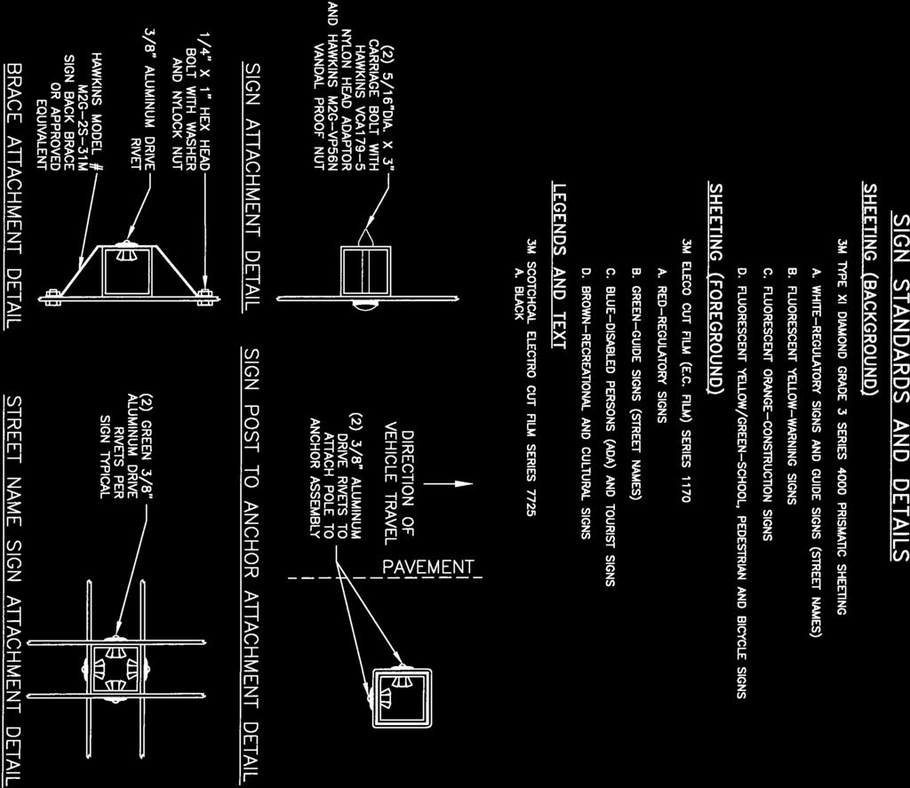
90
91
92
93
94 Section 5 - Street Lighting and Telecommunications Details SECTION 5 STREET LIGHTING AND TELECOMMUNICATIONS DETAILS CONTENTS Page 5-1 Street Lights Required Street Lights on Private Roadways Developer s Responsibility Utility Company Authorization General Plan Details Design Standards Street Light Design Details Master Planning Page 5-i January 20, 2017
95 Section 5 - Street Lighting and Telecommunications Details SECTION 5 STREET LIGHTING AND TELECOMMUNICATIONS DETAILS 5-1 STREET LIGHTS REQUIRED Streetlights shall be provided on all public streets. Streetlights may be required adjacent to parcels containing structures which are being improved or altered, depending on the nature and extent of the work. Illustrations of streetlights generally required are shown on Standard Drawing 5-1 and STREET LIGHTS ON PRIVATE ROADWAYS Streetlights may be required on private roadways serving more than 4 residences or serving a commercial use, as determined by the County Engineer. For planned developments, residential, commercial, and industrial developments where the internal streets are private, a private street lighting system will be required for the internal non-dedicated streets, in addition to public street lighting provided by the Developer on the external public street frontage. 5-3 DEVELOPER'S RESPONSIBILITY Existing streetlights which must be relocated or repositioned as a result of the construction of new streets or driveways into a development shall be the responsibility of the Developer. A new service can with a step-down transformer, required as a result of the modification, replacement or relocation of an existing utility service pedestal shall be the responsibility of the Developer. It shall be the responsibility of the Developer to ensure that the existing street light system remains operational until the new street light system to replace it is completed and functioning correctly. The Developer shall coordinate with electric utility for planning, design, preparation of plans, financing (pay all fees and costs) and operation, as required to install new streetlights. The Developer shall submit joint trench utility plans to the County showing the installation of streetlights. All streetlights will be publicly owned (by County or Community Service District) and maintained by the electric utility via standard LS-series rate charges. Any existing private streetlight to be relocated as part of the project shall be converted to a publicly owned light. In certain limited cases, the lights may be owned and maintained by the electric utility, as directed by the County Engineer. 5-4 UTILITY COMPANY AUTHORIZATION A written notice from the serving utility company, stating that line clearance and service have been checked and that the street lighting design meets utility standards and will be served by the utility, shall be submitted to the County Engineer for all developments. 5-5 GENERAL PLAN DETAILS The plans shall show and identify all street lights to be installed, all existing lights in the immediate vicinity of the project, all conduit and conductor runs, service points, trees, and all applicable provisions and details specified in these standards. On subdivision projects, a separate plan sheet shall be included for the street lighting system. This plan sheet may be combined with a signage plan. In addition, joint trench composite plans shall be submitted. Street lights (exclusive of other required information) shall also be shown on street plan and profile sheets. In addition to the above, the following shall be required on the street light portion of subdivision plans, even though duplications may be involved: Page 5-1 January 20, 2017
96 Section 5 - Street Lighting and Telecommunications Details All details of street light construction. A signature block conforming to Standard Drawing 3-2. Utility lines and public utility easements. Names of adjacent subdivisions. Intersecting property lines of adjacent properties. Legend indicating electrical symbols. A North arrow and appropriate scale. (1" = 10' to 1" = 100') All existing street lights on both sides of any streets. All new tree installations shall be more than 10' from street lights. All trees within the vicinity of the conduit runs or proposed streetlights. Street lights shall be located at least 15 feet away from any fire hydrant. 5-6 DESIGN STANDARDS A. Street lighting shall be designed in conformance with the "American National Standard Practice for Roadway Lighting" of the American National Standards Institute (ANSI/IESNA RP-8). The following table may be used as guidance for small projects, as determined by the County Engineer. Page 5-2 January 20, 2017
97 Section 5 - Street Lighting and Telecommunications Details TABLE 5-1 STREET LIGHTING GUIDE Street Classification Width (Feet at Face of Curb) Typical Pole Height (Feet) High Pressure Sodium Lamp (Watts) Distribution Type Typical Spacing 1 (Feet) Maintained Illuminance (Ft. Candles) Local Residential, Local Residential Low-Volume, Primary Residential II mid-block III intersections Collector III Industrial III Arterial (2-lane) III Arterial (4-lane) III Bike Path II Open Space - 14 to III, IV or V Note 4.17 Note 1: Standard Cobra style with 8 mast arm. Post top style requires review of illuminance based layout. Note 2: Lights mounted back to back on single pole in median. Note 3: Standard post top style along bike paths. Note 4: Calculations to be performed by the lighting designer. B. Data and calculations indicating compliance shall be submitted for review, when required by the County Engineer. The electrical system shall be designed for 120 volts single phase. In special circumstances, the design voltage may be increased to 240 volts. Voltages higher than 240 will not be allowed. Electronic copies of light photometric distribution patterns shall be provided for any non-standard lights. C. Lumens used to calculate the Average Illuminance shall be based on 80% of the manufacturer s value for the lamp. The luminaire depreciation factor (dirt accumulation) shall be 60%. D. Lamps other than High Pressure Sodium are not allowed. E. Light Spacing may be adjusted ±10% to allow for driveways and other physical obstacles. F. Open space design criteria shall be reviewed and approved by the County Engineer on a case by case basis. G. Provide luminosity plan. H. Provide shields on house-side of luminaire. Page 5-3 January 20, 2017
98 Section 5 - Street Lighting and Telecommunications Details 5-7 STREET LIGHT DESIGN DETAILS A. Intersections: Intersections shall have at least one streetlight. Intersection street light locations and the number required shall conform to Standard Drawings 5-3 and 5-4. B. Cul-de-sacs: All cul-de-sacs exceeding 130 feet in length, measured from the street light location at the intersection to the right-of-way line at the end of the cul-de-sac, shall have a street light within the bulb. The location of the streetlight within the bulb shall conform to Standard Drawing 5-4. C. Bike Paths: Streetlights shall be placed as indicated in the Street Lighting Guide table, and at both ends. D. Spacing: The maximum street light spacing, measured along the street centerline, shall conform to the above table. Streetlights on arterial streets shall be staggered. Double median poles will be considered on a case-by-case basis and require special approval. E. Street Light Poles: All street light poles shall be of galvanized steel, aluminum or concrete, as required to match nearby facilities. Poles shall be identified on the plans or in the special provisions. Identification information shall include material type, bolt circle diameter, luminaire mounting height, pole dimensions and length of mast arm. The County Engineer may approve special or unusual designs if warranted by the character of the surrounding neighborhood. Where special or unusual design street light poles are not listed in the Caltrans Standard Specifications, the Developer shall supply additional poles to the County for future pole replacement. The minimum number of replacement poles to be supplied to the County shall be 10% of the poles being installed with any fractional percent rounded up to the next whole number. The position of the street light poles relative to sidewalk shall conform to Standard Drawing 5-5. F. Street Lights on Existing Utility-Owned Poles: When there are permanent existing utility owned poles with existing streetlights adjacent to the project, the existing streetlights shall be replaced with publicly owned streetlights in accordance with these standards. The Developer shall make all arrangements with the owning utility for disconnection and removal of existing pole mounted streetlights. G. Luminaires and Ballasts: 1. Luminaires shall be high-pressure sodium type with internal ballasts. The type of street light and the appropriate wattage shall be specified on the plans. All luminaires shall conform to the standards outlined in the Caltrans Standard Specifications; light distribution shall be ANSI type II or III per these design standards and shall be full cutoff type unless specified otherwise by the County Engineer. The light pattern for each luminaire shall be specified on the plans. 2. Ballasts shall conform to the standards outlined in the Caltrans Standard Specifications, except that for 70 and 100-watt high-pressure sodium luminaires the ballast shall be energy efficient. H. Service: All street light systems shall have underground service provided. Service points shall be provided within a utility easement immediately adjacent to or within the right-of-way and shall be open and easily accessible to the street frontage. Types of service are as follows: 1. A direct underground service consists of one light being served from a single service point. Whenever possible, new lights on developments adjacent to existing development Page 5-4 January 20, 2017
99 Section 5 - Street Lighting and Telecommunications Details shall connect to an existing service point. The service point may be in the form of a pullbox or a service pedestal installed by the Developer. See Standard Drawings 5-6 and 5-7 for design details. 2. Multiple service is two or more lights being served from a single service point installed by the Developer. The service point shall be a pullbox. Multiple systems shall have a service pedestal normally located adjacent to the PG&E service point. The service pedestal shall be a Caltrans Type III-AF, stainless steel cabinet. 3. The County Engineer may approve overhead service in unusual areas where it cannot be provided underground. The Developer s Design Engineer shall be responsible for all electrical details and modifications to the standards relating to overhead service. I. Pullboxes: All pullboxes, including the size, shall be shown and identified on the plans. Pullboxes shall be installed adjacent to all street lights, at junction points of conduit runs, and when distance between pull boxes exceeds 200 feet long. The standard pull box shall be a Caltrans #3½, with the cover labeled Street Lighting, and shall be located at least 20 feet from any fire hydrant. J. Conductors: All conductors, including quantity and size, shall be identified on the plans. Unless otherwise specified, conductors shall be single conductor, solid or stranded copper, sized in accordance with these standards and the National Electrical Code. 1. On a direct underground service, the minimum conductor shall be No. 8 A.W.G. In general, conductors larger than No. 2 A.W.G. will not be allowed. 2. On multiple services, the minimum conductor size from the service point to the service shall be No. 8 A.W.G. 3. The size of each conductor from the service point to the luminaires shall be such that the voltage drop along each circuit will not exceed 7% for 2-wire systems and 6% for 3-wire systems of the nominal service voltage to the farthest luminaire. The nominal service voltage to be used in the voltage drop calculations shall be 115 volts. Calculations shall be submitted substantiating the design criteria for every circuit, including the total load in amperes of each circuit at the service can. 4. The lamp amperage (or power demand) shall be based on total lamp wattage, including any losses in the ballast or other electrical components of the luminaire. 5. Where only one photocell is required in a multiple service system, it shall be connected to the service can with three No. 14 A.W.G. conductors. K. Photo Cell: A single photocell receptacle shall be provided on the luminaire nearest to the service point for multiple service containing four or more lights. All other light systems shall have a photocell in each luminaire. L. Conduit: All conduit runs, including the size, shall be shown and identified on the plans. The minimum size for new conduits is one-and-one-half-inch (1½ ) diameter conduit. Minimum cover shall be 24 inches to finished ground in landscaped areas and 30 inches in roadway areas. For a system designed using the 3-wire system, only 2 circuits (one set of 3 wires) shall be allowed in any conduit. Circuits based on the 2-wire system and the 3-wire system shall not be mixed in any conduit. All circuits may, however, be mixed in the same conduit from the service can to the first pull box. Page 5-5 January 20, 2017
100 Section 5 - Street Lighting and Telecommunications Details The design may include more than two circuits in a conduit if the conductors for each circuit (2- wire) or set of circuits (3-wire) are identified by conductor insulation which is a solid color or a basic color with a permanent colored stripe. The identification stripe shall be continuous over the entire length of the conductor. New development shall install one-and-one-half-inch (1½ ) conduit, or larger as required, with one No. 10 A.W.G. stranded pullwire from the last light on each end of the system to the adjacent property line, where the adjacent property has no existing street lighting system. M. Electrical Equipment and Work: Control and switching equipment and fusing of all circuits shall meet the requirements of the National Electrical Code, the Basic Electrical Regulations, Title 24, Part 3, of the California Administrative Code, the rules of the National Board of Fire Underwriters, and Yolo County. 5-8 MASTER PLANNING Master planning is the determination of street light locations between control points. Control points are proposed street light locations at street intersections in accordance with the above sections and Standard Drawings 5-3 and 5-4, and existing streetlights. The purpose of master planning is to establish an overall uniform street light system that meets minimum requirements. Master planning shall apply to both sides of the street. The procedure is outlined as follows: A. Identify the nearest intersections each way from the street light locations being planned. Determine the location of the streetlights at the intersections in conformance with the design standards in the above sections. B. Identify any existing street lights situated between the intersections. C. Determine the distance between the adjacent designed intersection streetlights and/or adjacent existing streetlights, whichever are nearest to the street light locations being planned. D. Divide the distance into equal spaces between lights not to exceed the maximum spacing requirements specified in the above sections. E. Compare the light locations to intersecting property lines, driveways, pedestrian lanes, and other obstructions as follows: 1. If the location falls close to a property line and it can be adjusted to the property line while staying within the maximum spacing allowed, then the adjustment should be made. 2. Generally, streetlights should be situated at intersecting property lines for residential lots and parcels with minimal frontage (75 feet or less). The light spacing may have to be unbalanced, with additional lights being added to attain this and still comply with the maximum spacing allowed. 3. Street light locations shall be adjusted to miss driveways, mailboxes, utility boxes, and other obstructions by five feet, and shall be located at least 20 feet from any fire hydrant. F. Street light locations on arterial streets should be adjusted, when possible, to obtain a more uniform light distribution if there are existing street lights on the opposite side of the street. Page 5-6 January 20, 2017
101 Section 5 - Street Lighting and Telecommunications Details Standard Drawings Section 5 Street Lighting and Telecommunications Details Drawing Sheets Description Standard Street Light and Legend Post Top Street Light Typical Street Light Locations, Arterial Streets Typical Street Light Locations, Collector and Residential Streets Base Location for Street Light Single Light Direct Service Service Point Pull Box Electric Service Pedestal IT-1 1 Standard Cable Trench Sections IT-2 1 Fiber Optics & Signal Interconnect Pull Boxes IT X 7 Vault Detail 1 IT X 7 Vault Detail 2 IT X 5 Vault Detail 1 IT X 5 Vault Detail 2 IT-7 1 Fiber Optic Conduit Handhole Entry IT-8 1 Typical Fiber Optic Conduit Sweep Detail January 20, 2017
102
103
104
105
106
107
108
109

110
111
112


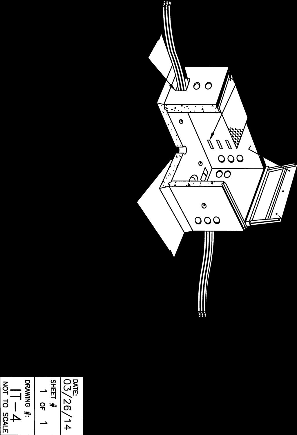


113
114


115


116
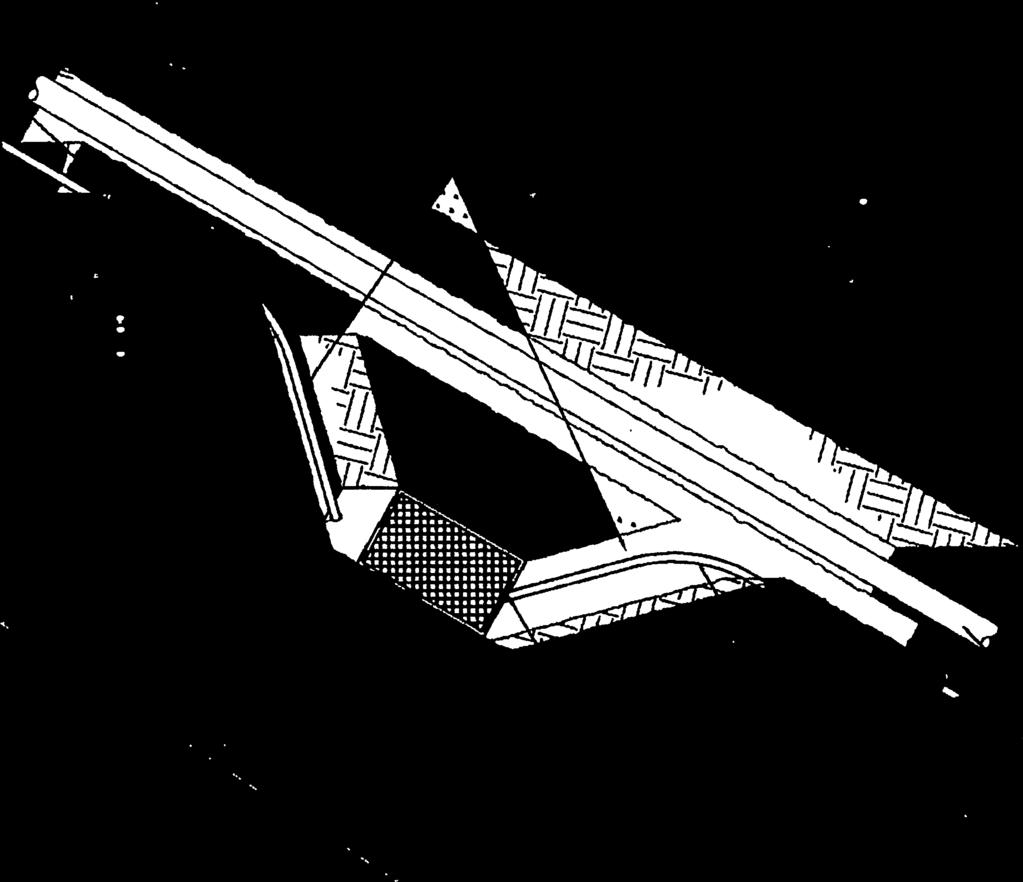


117
118 Section 6 Sound Barrier & Security Walls 6-1 LOCATION REQUIREMENTS SECTION 6 SOUND BARRIER & SECURITY WALLS Sound barriers or security walls may be required along the rear and side property lines of residential developments adjacent to freeways, major highways, arterials, collectors, and other ground level noise generators in order to achieve the noise objectives of the County of Yolo General Plan, Zoning Ordinance, or as required by the project conditions of approval. Rear and side yard security fencing adjacent to publically owned lands, rights of ways, or road easements shall not be wood fences. Acceptable materials for sound barriers are masonry or concrete. Where sound barriers are not a necessary component, security walls may be constructed of chainlink or tubular steel fencing. 6-2 DESIGN The sound barrier shall be designed to meet noise reduction objectives established for the project. Structural calculations prepared by the Design Engineer in accordance with Building Code requirements shall be submitted for review and permitting by the County Chief Building Official. Wall design details and submittals shall also be reviewed and approved by the County Engineer. Design Details shall include, but are not limited to: Materials; either masonry or concrete, including reinforcement Wall height and thickness Footings Earth retention allowances Construction requirements Special inspection requirements Architectural features and any painting, considering colors that can be matched for ease of graffiti abatement Standard sound barrier designs may be approved for use in the County of Yolo. Any such request shall include plan details and calculations prepared and signed by an appropriate Design Engineer. The Developer shall make an application and pay all related review and approval costs. Sound barriers shall be installed outside of public rights of way, and shall have a minimum design life of 30 years. Sound barriers constructed along freeways, or at the back of sidewalk along the outside of curved major streets, shall incorporate a barrier-type design element to minimize the potential for vehicles penetrating the wall. Other locations that represent a higher potential for run-off-road accidents shall be required to incorporate a Caltrans Type 60 (or equivalent) barrier-type design element. All open or non-reinforced cells in masonry block sound barriers shall be fully grouted. Special inspection shall be required. Decorative split face block, decorative caps, and decorative pilasters may be required. Page 6-1 August 5, 2008
119 Section 6 Sound Barrier & Security Walls 6-3 PLAN REQUIREMENTS All construction details for sound barriers and security walls, including the locations and limits, shall be shown on the site improvement plans. Sound Wall construction details shall comply with APWA Greenbook Standard Plan unless a project specific design is submitted along with design calculations for review and approval. Page 6-2 August 5, 2008
120 Section 7 Sanitary Sewers CONTENTS SECTION 7 SANITARY SEWERS 7-1 Design Criteria Flow Determination Design Flow Pipe Capacity, Slope, Velocity, Size, Depth And Material A Size B. Slope and Velocity C. Capacity D. Depth E. Material F. Testing Groundwater Requirements A. Geotechnical Reports Sewer Locations And Alignment Requirements A. General B. Location in New Subdivision C. Location in Existing Streets D. Easements E. Water Well Clearance F. Alignment G. Upstream Uses Trench Loading Conditions And Pipe Design A. Conduit Loading B. Safety Factor C. Bedding and Initial Backfill D. Special Pipe Strength Requirements Manhole Criteria A. General B. Spacing C. Elevation Criteria D. Construction Requirements E. Vacuum Testing Drop Connection Flushing Branch Sewer Services A. General B. Sizing Page 7-i August 5, 2008
121 Section 7 Sanitary Sewers CONTENTS C. Connection Limitations D. Material E. Location F. Depth G. Service Requirements in Developed Areas Creek or Canal Crossing Design A. General B. Design C. Construction And Material Jack and Bore Requirements Pump Station And Force Main Requirements A. Plans for Wastewater Pump Stations B. Specifications C. Other Requirements D. Design Factors to be Considered E. Site Improvements F. Structures and Appurtenances G. Pumps, Motors, and Controls H. Piping and Valves I. Emergency Provisions J. Miscellaneous K. Force Mains Sewer Improvement Plan Requirements A. General Requirements B. Plan and Profile Sheets C. Detail Drawings D. Connection to Existing Facilities Design Of On-Site Sewer Systems-Private Multiple Ownership Residential Developments A. Planned Unit Developments and Townhouses Multi-Structural Commercial And Industrial Developments Sewer System Master Plan (SSMP) For A Specific Area A. General Requirements B. Study Map C. Report Preparation Wastewater Treatment Systems Page 7-ii August 5, 2008
122 Section 7 Sanitary Sewers 7-1 DESIGN CRITERIA SECTION 7 SANITARY SEWERS These Improvement Standards shall only apply to sanitary sewer collection facilities to be maintained by a County Service Area or sewer maintenance district under control of the Board of Supervisors that provides extended sewer services. These Standards are minimum design criteria. The County Engineer may permit modifications or may require higher standards where unusual conditions are encountered. These Standards shall also apply to any privately owned and maintained sanitary sewer collection systems serving 4 or more residential units or any commercial or industrial uses. Where sanitary sewer facilities are to be maintained by a Community Service District or City, the standards of the District or City shall govern the design and construction of sanitary sewer facilities. 7-2 FLOW DETERMINATION Flow determination shall be based upon the approved zoning, existing land uses or General Plan land use designations, whichever produces the greatest flow. The minimum population density used shall be based on the latest US Census Tract data for single-family residential housing. Design flows shall be calculated using Table 7-1. TABLE 7-1 SANITARY SEWER DESIGN FLOWS Land Use Unit Minimum Average Daily Flow ( Gallons per Unit ) Peaking Factors 1 Single Family Residential (3.5 persons per unit) Multi-Family Residential (3.0 persons per unit) Residence Residence Commercial, Office Gross Acre 2 2, Central Business District Gross Acre 2 3, Light Industrial Gross Acre 2 2, Heavy Industrial Gross Acre 2 3,000 5, Recreation and Parks Gross Acre Elementary School Student 50 3 Middle School Student 50 3 High School Student : Peaking Factors may be increased or decreased based on flow peaking studies for trunk mains and pumping stations. 2: Subject to review and confirmation of intended uses and waste generation rates. Industrial uses may require private pre-treatment and/or peak reduction facilities. The infiltration and inflow allowance shall be 600 gallons per gross acre per day. 7-3 DESIGN FLOW Design flow shall be calculated using the average daily flow for the upstream service area, as described in Section 7-2, unless more current design criteria is available in a Sewer System Master Plan. Page 7-1 August 5, 2008
123 Section 7 Sanitary Sewers The following formula shall be used to calculate the design flow: Where: Q d = (Q a x PF) + I Q d = Design Flow Q a = Minimum Average Daily Flow PF = Peaking Factor I = Infiltration/Inflow Allowance 7-4 PIPE CAPACITY, SLOPE, VELOCITY, SIZE, DEPTH AND MATERIAL A Size: The minimum size sewer pipe shall be eight inches in diameter unless otherwise approved by the County Engineer. The minimum size sewer service lateral pipe shall be four inches. B. Slope and Velocity: Minimum slopes of sewer pipes shall be such that the velocity of flow in the pipe when full shall not be less than two feet per second. Manning's formula shall be used to determine the relation of slope, design flow, velocity, and diameter. The Manning s "n" value shall be Table 7-2 shows the minimum slopes for various pipe diameters. Pipe slopes that are less than those listed in this table shall not be used without the approval of the County Engineer. Pipes shall not be artificially oversized to justify the use of a smaller slope. The slopes indicated are based on a velocity of two feet per second with the pipe flowing full, or half full. TABLE 7-2 MINIMUM SLOPES Inside Diameter (Inches) Minimum Slope The maximum depth of flow at design conditions in any collector (12-inch inside diameter or less) shall be 0.7 of the pipe diameter. Mains larger than 12-inches in inside diameter may be designed to flow full unless direct sewer service connections are planned; in which case the 0.7 diameter maximum depth shall govern. C. Capacity: Pipe capacity and invert elevations, in all cases, shall be adequate to carry the design flow from the entire tributary area, even though said area may not be within the project boundaries. D. Depth: In the design of a system, one of the controlling conditions shall be that the collector system shall be at sufficient depth to provide a minimum slope for the sewer services of 1/4 inch per foot (or 2%), at the same time maintaining a minimum cover of 12 inches at any buildable location within the properties to be served, and a minimum of four feet of cover at the back of sidewalk, except that the depth shall be increased to provide minimum 6 inch clearance from underground (dry) utilities installed at the back of the sidewalk. Minimum depth of new sewer collectors or mains shall be 6 feet from finish grade to top of pipe. The maximum depth of sewer lines shall be 15 feet, unless approved by the County Engineer. A geotechnical study may be required to determine special backfill requirements for sewer pipelines exceeding 10 feet in depth. Page 7-2 August 5, 2008
124 Section 7 Sanitary Sewers E. Material: 1. Polyvinyl Chloride (PVC) C900 Class 200 DR 14 conforming to ASTM D1784 for pipes up to 12-inch, and AWWA C905 Class 200 DR14 for larger diameters. 2. Ceramic Epoxy lined Ductile Iron Pipe with a 40-mil-thick high build multi component lining materials consisting of Amine cured Novalac epoxy with at least 20% by volume ceramic quartz pigments. Protecto 401 Ceramic Lining, or equivalent. Encase ductile iron pipe in clear 4-mil HDPE wrapping tubes in accordance with ANSA/AWWA C105 standards. Secure wrap with three wraps of 10-mil HDPE tape, overlapping each wrap onehalf tape width. 3. ABS pipe and fittings at service lateral cleanout assemblies shall be Schedule 40 conforming to ASTM F 628 and ASTM D All products shall bear the seal of a nationally recognized listing or certifying agency. F. Testing: Sewer lines and laterals shall be air tested in accordance with ASTM F1417 Standard Test Method for Installation Acceptance of Plastic Gravity Sewer Lines Using Low-Pressure Air. Acceptance testing shall occur following completion of all trench backfill, and placement and compaction of aggregate base in streets. Sewer lines and laterals shall be balled and flushed, and a TV inspection shall be made, following placement of aggregate base for street, and prior to paving, to allow defective work to be repaired prior to paving. Complete color recordings and logs of TV inspections shall be submitted to the County. Defective work includes but is not limited to: Cracks or breaks in the pipe Joint separations > ½ Low spots (sags) > 1 depth Chipped pipe ends > ¼ Protruding, folded, or otherwise deformed gaskets or flexible connectors. Sewer laterals shall be TV inspected prior to final building occupancy to ensure that the laterals are free of debris and damage. 7-5 GROUNDWATER REQUIREMENTS Geotechnical Reports: A Geotechnical Investigation Report with groundwater handling or design recommendations shall be required for all plans where public or private sewer facilities are proposed for construction in high groundwater areas. In areas where groundwater is expected to be encountered above the flow line of sanitary sewer pipe, cement slurry backfill, concrete dams, geotextile wrapping of bedding rock, or other approved methods shall be utilized in the trench to retard the movement of groundwater through trench bedding material and minimize the potential for subsurface erosion. 7-6 SEWER LOCATIONS AND ALIGNMENT REQUIREMENTS A. General: All public sanitary sewers shall be placed within rights of way dedicated for public streets unless the County Engineer specifically approves the use of easements. In some streets, dual collectors may be required. There shall be a minimum horizontal clearance of ten feet between parallel water and sanitary sewer mains and the water main shall be higher than the sewer. At crossings, the water main shall be at least 12 inches above the sewer main. If a sanitary sewer force main must cross a water main, the requirements of Section 8-15.B shall apply. Page 7-3 August 5, 2008
125 Section 7 Sanitary Sewers B. Location in New Subdivision: In new subdivisions, sewers shall be located six feet southerly or easterly of street centerlines. C. Location in Existing Streets: The County Engineer shall determine where sanitary sewers shall be installed in an existing street, considering factors such as curbs, gutters, sidewalks, traffic conditions, traffic lane conditions, pavement conditions, future street improvements plans, and existing utilities. D. Easements: Permanent easements shall be a minimum of 15 feet wide for sewers up to 18 inches in inside diameter and a minimum of 20 feet wide for larger diameter sewers. Widths shall be increased as required to provide for trench wall slopes of 1.5:1 (Horizontal:Vertical) unless flatter slopes are required by existing soil conditions. Temporary working easements of adequate dimensions shall be provided to allow the construction within the permanent easement to be completed in a safe and reasonable manner. E. Water Well Clearance: No sanitary sewer interceptor, trunk main, collector, or service shall be placed closer than 100 feet to any water well, public or private, unless the well has been abandoned in full accordance with Yolo County Environmental Health Department permit requirements, or the location otherwise approved, in writing, by the appropriate regulatory (State and/or County) agencies. If a clearance of less than 100 feet is approved, all pipe within that distance from the well shall be of material approved by the County Engineer. In no case shall a clearance of less than 50 feet be allowed. F. Alignment: Alignment of all sewer pipe and structures shall be designed to provide a minimum 10 feet of clear separation from parallel existing or proposed water mains as a means of protecting the water main from contamination. Sanitary sewer lines shall pass beneath water mains at all transverse crossings and shall be placed to provide a vertical clearance of at least one foot between the respective pipes. A minimum of one-foot clearance from all other utilities and/or improvements shall be provided, in accordance with Department of Health Services requirements and California Waterworks Standards, unless otherwise approved by the County Engineer. 1. Horizontal alignment shall be parallel to the street centerline and straight between structures wherever possible. Minimum radius for sanitary sewers 8 inches through 12 inches in diameter shall be at least 140% of the pipe manufacturer s recommendation for minimum radius of curvature. A larger radius shall be used wherever practicable or where necessary to avoid joint deflection in excess of 80% of the pipe manufacturers' recommended maximum. Only factory joints will be allowed. Curve information shown on the plans shall include pipe radius (if not concentric with street centerline), sub-tended angle, length, and if needed, maximum pipe lengths. 2. Vertical alignment shall provide a constant slope between manholes. If a change in grade is necessary, construction of a manhole shall be required unless the County Engineer approves the use of a vertical curve. In such case, elevations shall be shown at ten-foot intervals throughout the length of the vertical curve. Joint deflections in excess of 80% of the pipe manufacturers' recommended maximum will not be allowed. Only factory joints will be allowed. G. Upstream Uses: Each property owner is responsible for the installation of a collector sewer across their property and/or frontage that will serve all upstream uses within an upstream service area. Page 7-4 August 5, 2008
126 Section 7 Sanitary Sewers 7-7 TRENCH LOADING CONDITIONS AND PIPE DESIGN A. Conduit Loading: For rigid conduit, Marston's formula shall be used to determine the load placed on the pipe by backfill. The procedure for rigid pipe is described in the ASCE Manual and Report of Engineering Practice 60 and in similar handbooks. In the absence of specific soils data, as determined by a Geotechnical Engineer, a soil weight of 120 p.c.f. and a k u factor of shall be used. For flexible conduits, Marston s formula for flexible conduits as shown in the ASCE Manual and Report of Engineering Practice No. 60 and in similar handbooks shall be used to determine the load placed on the pipe by the backfill. The maximum load allowable shall be determined by pipe deflections computed by the Iowa Deflection Formula (or Spangler s Formula.) The soils reaction modulus (E ) shall be estimated using a method acceptable to the County Engineer, and shall consider the modulus values of both the native and the bedding materials (ATV method). The bedding soils reaction modulus (E ) used in the deflection calculation shall be 1,000 psi for Type II bedding, utilizing imported material to twelve inches above the top of the pipe. Deflection lag factor shall be 1.5. In the absence of specific soils data, as determined by a soils engineer, a soil weight of 120 pcf, a k u factor of 0.110, and a bedding constant of shall be used. Placement of flexible conduits within soils equivalent to Class V and types MH and CH of Class IV ASTM D2321 material will not be permitted unless approved by the County Engineer. B. Safety Factor: A safety factor of 1.25 shall be used for reinforced concrete pipe, and 1.5 for all other rigid pipe. Only the three edge bearing strength of the pipe shall be used in the computations for rigid pipe. C. Bedding and Initial Backfill: Bedding types and factors shall conform to Standard Drawing 7-4. Bedding and initial backfill type shall be as necessitated by height of cover over the pipe, trench width, pipe strength, and other factors used to determine safe pipe loading. Special attention shall be given to backfill requirements for deep trenches, pipes located in State rights-of-way and for pipes placed in areas where trench width is excessive, such as in the vicinity of bore pits. See Section 7-13 regarding this condition. Any special backfill requirements shall be noted on the plans. Unless otherwise noted on the plans, bedding and initial backfill for all pipe sizes shall be Type II, with trench widths subject to limitations set forth in Standard Drawing 7-4. The minimum trench width for all rigid pipe shall be pipe O.D. plus 12 inches. Type III bedding and initial backfill are intended primarily for emergency field conditions. Their use shall normally not be specified on the plans and shall require specific written approval of the County Engineer before use. D. Special Pipe Strength Requirements: Ductile iron, or other high-strength pipe approved by the County Engineer, shall be used whenever cover is greater than 25 feet, or extra support strength is required (such as to resist traffic loading). Ductile iron pipe or other high-strength pipe approved by the County Engineer, shall be used whenever cover is less than four feet, or insufficient clearance exists between the sewer pipe and rigid or load transmitting structures. 7-8 MANHOLE CRITERIA A. General: Manholes shall be placed at all intersections of sanitary sewer mains, at any change in pipe slope, at any angular or abrupt change in horizontal alignment, at the end of any main terminating in a cul-de-sac, at the end of all permanent mains 120 feet or more in length, and at the end of any temporary main more than 200 feet in length. All manholes from which sewer main extensions are anticipated shall have a pipe stub installed at the grade and in the direction of Page 7-5 August 5, 2008
127 Section 7 Sanitary Sewers the anticipated extension. Summit manholes connecting two sewer collectors are not acceptable. Manholes may be required on lateral lines serving industrial sites in accordance with Yolo County Code section B. Spacing: Maximum spacing of manholes shall be 400 feet for all straight sewer mains of teninch diameter or less. Where sewers are installed with curvilinear alignments, manholes shall be placed at the beginning or end of such curves, and the distance between manholes shall not exceed 300 feet. Where the length of the curve is in excess of 300 feet, manholes shall be placed at intermediate points along the curve. Reverse curves require a manhole at the point of tangency between the curves. C. Elevation Criteria: When two mains of the same size enter a manhole such that the flow of one must change direction more than 20 degrees, or if flow in a single main must change direction more than that amount, the invert grade at the exit must be at least 0.10 below that of the entrance pipe, but in no case shall the crown of the exit pipe be lower than the invert of the entrance pipe. If the pipes entering and exiting any manhole are not of the same size, the crown of the exit pipe shall never be higher than the crowns of pipes entering the manhole. Manholes not meeting these conditions shall be governed by inside drop connection requirements. D. Construction Requirements: Manhole construction shall conform to the provisions of Standard Drawings 7-1 to 7-3. Lock-type or pressure-type manhole covers shall be used on manholes located in easements, and in areas subject to flooding. If the distance from the crown of the pipe to the top of the rim is less than 6 feet 11 inches, 18-inch high cone shall be used. Manholes shall use flat slab tops that have through mains and less than 5 feet 8 inches from the crown of the pipe to the rim. The plans shall note that the frame on manholes located in unimproved areas shall be set 1.0 above existing ground level, provided with a concrete collar and an object marker. Manholes located outside of paved areas shall be provided with all-weather access, and shall be located in the center of a 10 foot diameter level all-weather pad, so that they are accessible to maintenance personnel and equipment. E. Vacuum Testing: All manholes shall be vacuum tested in accordance ASTM C Acceptance testing shall occur following placement of aggregate base and prior to paving. 7-9 DROP CONNECTION Drop connections are not allowed, but may be approved by the County Engineer. If approved, manholes containing drop connections shall be coated with a protective coating of either a) 40-mil T-lok PVC liner, Ameron Protective Coatings, b) CCS Coating, high build chemical resistance 40-mil epoxy coating by ChemCo Systems, c) Raven 405 epoxy, 60 mils, d) or equivalent. There shall be no more than one inside drop connection into a four-foot diameter manhole FLUSHING BRANCH A flushing branch may only be used at the end of a collector less than 200 feet in length if the collector extends to a subdivision boundary and if there are definite plans for its extension. If a collector extends to a subdivision boundary, is planned for definite extension, and has no sewer service connections, it may be capped. Flushing branches shall conform to Standard Drawing SEWER SERVICES A. General: Sewer service laterals shall conform to Standard Drawing 7-5 and shall be aligned at right angles to the main unless otherwise approved by the County Engineer. The sewer service shall extend from the collector sewer to the lot being served. Sewer services shall extend at least one foot beyond the edge of the pavement of any private road. Easements of adequate width to Page 7-6 August 5, 2008
128 Section 7 Sanitary Sewers accommodate the services shall be obtained. A plan and profile of any sewer service shall be supplied to the County Engineer upon request. Construction of the cleanout to grade for all sewer services is required. The cleanout location shall be accurately staked with a 4"x 4" post until final landscaping is completed and service connections are completed. The location of all sanitary sewer services shall be permanently marked with a 2-inch tall S set in the top of concrete curb. Where curbs do not exist, a 2 x2 concrete pad shall be placed around the sewer cleanout box, and a permanent post (2 diameter, galvanized steel, painted white) shall also be installed to mark the location of the sewer cleanout box. B. Sizing: Normal sewer service size is four inches for residential and six inches for multi-family or commercial. Six-inch or larger sewer services shall serve schools and other developments expected to contribute high sewage flows. In addition, sewer services shall be sized according to requirements of the Uniform Plumbing Code, and as determined by the Engineer. If the sewer service and collector are of the same size, a manhole must be constructed. C. Connection Limitations: Sewer services shall not directly connect to sewer mains designed to flow full or to mains more than 16 feet in depth without the approval of the County Engineer. D. Material: The "T" or wye and the sewer service shall be of the same material as the collector to which it connects. E. Location: When sanitary sewers are constructed as part of new subdivision improvements, a separate sewer service shall be constructed between the main and each lot. In new subdivisions or developed areas, unless specifically requested otherwise in writing by the property owner or Design Engineer, sewer services shall be placed on the low side of any subdivision lot or similar parcel with two percent or greater slope across the front. Otherwise, the sewer service shall be placed in the center of said lot or parcel. Consideration shall be given to trees, improvements, proposed driveways etc., so as to minimize interference when the sewer service is extended to service the house. If the property is located such that sewer service is available both to a main located in an easement and also in right of way, sewer service shall be connected to the right of way location unless otherwise approved by the County Engineer. No sewer service shall be located such that future on site construction will result in the main being in such proximity to a water well or water main or water service that applicable health standards will be violated. F. Depth: The Design Engineer shall verify the adequacy of the normal sewer service depth at the edge of easement or right of way to serve the intended parcel. A depth of four feet to crown of pipe, measured from the ground surface at the back of sidewalk shall be considered normal sewer service depth, except as allowed in the event of conflict with dry utilities, as provided for on Standard Drawing 7-5. Whenever greater depth is required, the Design Engineer shall designate the invert elevation of the sewer service at the edge of the right of way or easement on the construction plans. If a joint trench is being utilized for other utilities, the Design Engineer shall indicate on the plans that a Joint trench will exist and shall adjust service elevations as necessary. It shall be the responsibility of the Design Engineer to arrange for coordination of the grade of utilities located in the joint trench and the sewer services. G. Service Requirements in Developed Areas: In developed areas, a sewer service shall be provided to each legal parcel containing a source of sewage and having a property line less than 200 feet from a collector. A property owner's request for sewer service location shall be honored whenever practicable. Parcels having two or more sources of sewage must have an independent sewer service provided to each sewage source. A sewer service shall be provided to each subdivision lot or lot similar as to size and possible development. At an early stage of design, the Design Engineer shall send every property owner affected by the proposed work a questionnaire requesting, in writing, the owner's preferred sewer service location. In absence of a response to this questionnaire, the Design Engineer shall provide a sewer service as required by this Section. Page 7-7 August 5, 2008
129 Section 7 Sanitary Sewers In addition, when sewer services are staked immediately prior to construction, each property owner shall be given notice that he should give consideration to the staked location of his sewer service and, if not satisfactory, immediately notify the Design Engineer. The date of notification, nature of change, and other pertinent information shall be recorded. Compilation of this information shall be the responsibility of the Design Engineer and the information shall be furnished to the County Engineer upon request CREEK OR CANAL CROSSING DESIGN Advance approval of the County Engineer and of other appropriate agencies is necessary prior to initiating design. Copies of required permits shall be provided to the Department prior to approval of the plans. A. General: In all cases, the proposed future creek or canal bed elevation shall be used for design purposes. Crossing details of pipe, piers, anchorage, transition couplings, etc., shall be shown on a detail sheet of the plans. B. Design: Calculations shall be submitted which clearly indicate the design of the pipe and supports regarding impact, horizontal and vertical forces, overturning, pier and anchorage reactions, etc. C. Construction and Material: For collector sizes ten inches and smaller, ductile iron pipe or other pipe material as approved by the County Engineer shall be used under the full channel width, plus ten feet each side, unless the pipe is four feet or more below the channel bed elevation. For main sizes twelve inches and larger, pipe used shall be as directed by the County Engineer. Special care shall be taken to provide a firm base for the pipe bedding. The plans shall specify that all soft or organic material within the channel banks shall be replaced with select imported backfill. In addition, the pipe shall be encased in concrete or soil cement shall be used to protect the pipe for the full width of the channel. Unless otherwise directed a clay soil plug shall be required at the top of the pipe at the downstream side of the crossing. The plug shall be a minimum of four feet in length, shall extend the full width of the trench, and shall extend twelve inches above and below the pipe or as approved by the County Engineer. If the pipe must cross above the channel, ductile iron or welded steel pipe shall be used. Steel pipe may be cement lined and coated, fusion epoxy lined and coated, or glass lined; the County Engineer shall specify or approve the type of coating and lining specified, and the gauge, class, or thickness of the pipe. Reinforced concrete piers of adequate depth shall be located as necessary for adequate support of the pipe. The pipe shall be held in cylindrical cradles, formed in the pier tops, by galvanized steel straps, with galvanized anchor bolts of adequate size. Cushion material shall be placed between the pipe, clamps, and support. The invert elevation at the point of maximum deflection of the suspended pipe shall be invert of the pipe at its downstream support JACK AND BORE REQUIREMENTS Where use of conductor casing is specified, the casing shall be reinforced concrete pipe. The casing shall be of sufficient diameter to allow dry sand to be blown into the void between the carrier and the conductor and to allow adjustment of the carrier pipe to grade. Normally, an inside diameter six inches greater than the outside diameter of the couplings of the carrier pipe is sufficient. Reinforced concrete pipe conductors must be designed for the loading condition and, if jacked, the additional loading imposed by the jacking operation. Direct dry boring of reinforced concrete pipe and of the portion of sewers and sewer services, which pass beneath curbs and gutter, sidewalks, and other obstructions, up to a maximum length of 15 feet, is Page 7-8 August 5, 2008
130 Section 7 Sanitary Sewers permissible. Six-inch and smaller pipelines may be installed by wet boring where approved by the County Engineer. Pipe material used in the small size dry and wet bores shall be ductile iron pipe, or Class 200 (DR-14) PVC pipe conforming to the requirements of AWWA C900. Backfill in bore pits shall be given special attention with respect to preventing structural failure of the pipe entering or exiting the conductor, and adequate bedding and initial backfill shall be specified PUMP STATION AND FORCE MAIN REQUIREMENTS Every phase of pump station design, including force mains, shall be closely coordinated with and shall be under the direction of the County Engineer. Pump station features shall include, but not be limited to, buried non-corrosive wet well, duplex (redundant) submersible pumps & motors, above ground weather proof enclosure for automated controls, telemetry, SCADA, remote dialing alarms, phone service, power supply, backup power generator powered by natural gas or propane (LPG), lighting, all weather access, sulfide related corrosion control or reduction, life cycle cost analysis of proposed features, etc. Force Main features shall include, but not be limited to, non-corrosive pipe materials, pipe routing, exit manhole sulfide related corrosion control or reduction, life cycle cost analysis of proposed features, etc. A. Plans for Wastewater Pump Stations 1. General Layout: a. Plot plan showing layout of site and building(s), including driveway and number of parking stalls, exterior piping and appurtenances, fencing, and utilities. Property ties shall also be shown. b. Plans and details of grading, drainage, erosion control, landscaping, and sprinkler system. c. Show FEMA flood elevations if area is in a 100-year flood plain. 2. Detail Plans: a. Architectural plans, elevations, and details. b. Structural plans, elevations, sections, and details. c. Utility plans (electrical, mechanical, etc.) showing exact location and elevation to prevent damage from future excavations. d. Mechanical plans including pump, isometrics, plumbing, ventilation, air condition and other equipment installations, piping layout, and details. e. Electrical and telemetering plans and details including conduit schedule and lighting fixture layouts, control equipment arrangement, and wiring diagrams (one line and elementary control diagrams) for power distribution and controls. f. Wastewater level control arrangement for operating pumps and alarms. g. Other plans, sections, elevations, schematics, details and notes, as required, to adequately show the proposed construction. B. Specifications: All work shall be in accordance with these Improvement Standards. Special provisions shall supplement the Improvement Standards and shall specify in detail the construction of the wastewater pump station, and all appurtenances. C. Other Requirements: 1. Design Calculations: Calculations pertinent to the design shall be submitted to the Planning and Public Works Department. Such calculations shall be used by the County for determining the adequacy and feasibility of the proposed facilities under review. Any failure on the part of the Developer or authorized representatives to submit such calculations will delay the review and approval of the desired project. 2. Revisions to Approved Plans and Specifications: Any deviations from these specifications shall be approved by the County Engineer in writing before such changes are made. Any deviations shall be submitted well in advance of any construction work which will be affected by such changes to permit sufficient time for review and approval. Page 7-9 August 5, 2008
131 Section 7 Sanitary Sewers 3. Operation During Construction: Existing facilities and pump station units shall be kept in operation during construction. 4. Equipment Manuals: Equipment manuals shall be provided for each pump station. The manuals shall contain sufficient information on the installation, operation, maintenance, and repair of the pump station equipment. Manuals shall be bound in looseleaf D binders. Folders shall contain only the information in relation to the equipment furnished. Each binder shall be labeled on its front cover and spine with the name of the facility and subject matter. Two sets of manuals shall be provided to the County. 5. Facilities Operations and Maintenance Manual: A detailed operations and maintenance manual for the facilities to be constructed shall be required for all pump station projects. The manual shall give the operations and maintenance personnel the proper understanding, techniques, and any other information necessary to efficiently operate and maintain their facilities. Operations and maintenance manuals shall comply with all applicable State and Federal statutes, ordinances, and regulations. Two sets of manuals shall be provided to the County. 6. Initial Start-Up Procedure Training: Services of field engineers or qualified personnel for all equipment provided shall be required to assist and instruct the County's operating and maintenance personnel. Such services shall commence before final acceptance testing. 7. Spill Prevention Plan and Emergency Response Plan: The facility s O&M manual shall include sufficient operating instructions in the form of a spill prevention plan to prevent spills. The emergency response plan shall also provide instructions to the operator on how emergencies are to be handled. Two sets of manuals shall be provided to the County. 8. One Year Certification: A certification shall be prepared after one year of facility operation documenting the performance of the facility. This certification is intended to confirm that the facility is operating as planned and there are no problems with the equipment. The certification should be prepared by the facility designer, construction manager, or other registered engineer approved by the County. D. Design Factors to be Considered: 1. Type of Station (Built-In-Place Wastewater Pump Station): All pump stations shall be builtin-place and may be either dry or wet well type. Premanufactured pump station systems may be considered upon review by the County Engineer. 2. Wastewater Flows and Design Capacity: a. Wastewater Flows. Wastewater flows shall be determined in accordance with County Improvement Standards. b. Design Capacity. Wastewater pump stations shall be designed to discharge design flows. c. Location: Wastewater pump stations shall be located where tributary areas will be most effectively serviced and where development, construction, and operational costs would be at a minimum. Pump stations should not be subject to flooding and shall be readily accessible. Wastewater pump station sites shall be adequate to allow on-site parking of service trucks and equipment and to buffer adjoining properties from noise. Future modification and expansion requirements shall be given consideration. E. Site Improvements: 1. Grading: Wastewater pump stations shall be located two feet (2') above 100-Year Flood Level and provided with adequate drainage facilities to carry away storm waters. Adjacent properties shall not be jeopardized by such provisions. 2. Driveways and Parking Areas: Paved driveways and parking areas shall be provided for service trucks. Width of driveways shall be 12 feet minimum. Pavement shall be asphalt or Portland cement concrete. Concrete curbs shall be required for all pump stations. Entrance gates shall be set inward, toward the station, at least 18-feet to allow trucks entering or leaving the station to pull off the adjacent street. Page 7-10 August 5, 2008
132 Section 7 Sanitary Sewers 3. Fencing: Pump station sites shall be fenced in with a six-foot (6') high fence or wall. Masonry walls or other approved types of enclosures are required if pump station is located adjacent to a residential project. Where chain link fences are used, wire fabric shall be nine gauge minimum, galvanized, and plastic coated with color determined by the County. In isolated areas, three strands of barbed wire should be installed along the top of the fence on an arm projecting outward at an angle of 45 degrees. A one foot (1') wide gravel strip shall be provided under fencing. Gravel strip shall be contained with redwood or other approved durable material headers. 4. Gates: Gates shall be provided with heavy duty padlock hasp fixtures and shall be designed for safe opening and closing during strong winds. At facilities where PG&E transformers and/or meters are installed within the station's perimeter, hasps shall be designed to accommodate two padlocks. Design shall allow access with either padlock removed. 5. Landscaping: Sites shall be landscaped to blend with the surrounding environment to render a pleasing overall appearance. Consideration shall be made to minimize groundskeeping maintenance. Chain link fencing shall be screened with landscaping. 6. Sprinkler System: Automatic sprinkler systems shall be installed for lawn/foliage irrigation. F. Structures and Appurtenances: 1. Architectural Design: Wastewater pump stations shall be architecturally designed to be in harmony with surrounding development. Materials shall be selected to keep construction and maintenance cost at a practical level. As much as possible, non-corrosive materials shall be used. All architectural design shall be prepared by a Registered Architect. 2. Substructure: Built-in-place pump station substructures shall be reinforced concrete construction. All substructures shall be waterproof and watertight. Test borings shall be made to determine the soil characteristics and ground water conditions at all pump station sites and foundations shall be suitably designed. Consideration shall be given to flotation during construction and/or flooding condition. Ensure that NPSH requirements of pump are met. Structural backfill for the lift station shall be placed as engineered fill, in lifts not exceeding 12 inches in compacted thickness. Each layer shall be uniformly moisture conditioned to at least the optimum moisture condition and compacted to at least 95% of the maximum dry density per ASTM D specifications. 3. Backfill: Backfill around the lift station well shall consist of clean crushed rock with 100% passing through a one inch (1") sieve and no appreciable amount passing through a #4 sieve. A minimum of 12 inches (12") of crushed rock shall be placed at the base of the sewer lift station footing for stabilization and extending a minimum of 12 inches (12") outside the edge of cast-in-place or pre-cast base. In all areas the crushed rock shall be separated from the native material with an approved non-woven geotextile fabric. With approval of the County Engineer, excavated soils may be used for backfill, after required drying has occurred to allow the specified degree of compaction to be achieved. Imported soils must be free of organic concentrations, rubble or debris and must have approval of the County Engineer. The contractor may find it necessary to use deep wells to lower the water table in lieu of using sump construction and pumping. If sheet piling is used the contractor shall extend the tips to a sufficient depth to prevent quick conditions or sand boils from occurring. The excavation for the sewer lift station may require the contractor to use special construction techniques, which may include but not limited to, sloped excavation, shoring and/or sheet piling, or a combination of methods. The contractor shall submit to the County Engineer for review and approval all shop drawings and proposed methods of construction. 4. Dry Wells: Dry wells shall be sized to meet space requirements for equipment, piping and ease of maintenance. Adequate working space, at least two feet (2') clear, shall be provided between and around pumps and other equipment. Provide three feet (3') clearance for electrical equipment to comply with the National Electrical Code. Space and provisions for planned future pumps and equipment shall also be provided. Page 7-11 August 5, 2008
133 Section 7 Sanitary Sewers 5. Wet Wells: Wet wells shall be designed on the basis of minimizing deposits of solids, preventing wastewater from becoming septic, and avoiding frequent starting of pumps. Minimum pump cycle (period from start to start) for any one pump shall be 5 minutes, but not less than the pump manufacturer s minimum pump cycle time rating. Maximum retention time of wastewater in wet wells shall be 30 minutes at average flow (total wet well wastewater volume shall be used in computing retention time). Wet wells shall have a minimum inside width of five feet (5') and shall be sized to keep wastewater levels within the following limits: a. High water level. Desired: at invert of incoming sewer. Maximum: at crown of incoming sewer. b. Low water level. Not lower than top of pump casing. c. Vertical distance between pump start and stop levels. Six inches (6") minimum. d. Floors shall have a slope of 1:1 minimum, sloping towards a hopper bottom. The hopper bottom shall be designed for proper installation and function of pump suction inlets. Influent lines shall be designed without vertical drops into the wet well to minimize release of entrained air/gases. The wet well shall be divided into two or more sections, properly interconnected, to facilitate repairs and cleaning. Wet wells shall have a minimum 40-mil PVC T-lock lining to protect against hydrogen sulfide corrosion. 6. Access. Reinforced concrete or structural steel stairways shall be provided for access to dry wells. Stairways shall have a clear passage of at least 30 inches. Stairs shall be provided with permanent non-slip treading. Access shall be provided to all wet well compartments. Access manholes shall be located to best facilitate maintenance operations. 7. Ventilation. Dry well shall be ventilated by a mechanical air exhaust system providing at least one air change every three (3) minutes. Outlets of exhaust system should not be located less than 12 feet from any opening except when exhausting through the roof. Ventilation exhaust shall be located downwind of any inlet openings. Velocity in air ducts shall not exceed 1500 fpm. When required fan capacity is large, the use of two fans shall be considered. Switches for the operation of the ventilation equipment shall be interlocked with the dry well light switch. Ventilation shafts shall be provided for wet well compartments with only one access opening. 8. Drainage. Dry well floors shall be constructed to drain by gravity into trench drains channeled to a sump. The sump pump shall be submersible. Minimum sump pump capacity shall be 25 gpm with exception of stations equipped with water seal systems, hydraulic operated cone-check valves, or similar type equipment. These stations shall be provided with duplex submersible pumps, each capable of pumping at least 50 gpm. A switch for lead/lag operations shall be provided at the Motor Control Center (MCC). Sump pump discharge shall enter the wet well adjacent to and as high as possible to the ground floor level. Trench drains shall be covered with corrosion resistant gratings. Floor framing and anchoring devices for gratings shall be 316L stainless steel. 9. Superstructure: All pump stations shall have a superstructure. a. Floor Elevation and Area. The latest flood zone map shall be consulted. Floor areas shall be adequate for mechanical equipment, electrical equipment and controls, sanitary facilities, storage, and future expansion. Adequate working space, at least two feet (2') clear, shall be provided between and around all equipment. Provide three feet (3') clearance for electrical equipment to comply with the National Electrical Code. b. Height. Height of superstructure shall provide adequate working height. Whenever possible, height of superstructures shall be adequate to permit the removal of motor rotor from its stator or the removal of other equipment of larger size with the installed hoisting equipment. c. Materials of Construction. The following materials are acceptable for construction of superstructures: Page 7-12 August 5, 2008
134 Section 7 Sanitary Sewers i. Beams and Columns: reinforced concrete or structural steel. ii. Roof: reinforced concrete. iii. Wall: masonry or reinforced concrete. d. Insect Screens. All structure openings for ventilation or light, except doorways, shall be equipped with removable stainless steel insect screens. e. Doors. Doors shall be of adequate size to permit removal of pumps, motors, and other equipment. Locks shall be keyable to the Department of Planning and Public Works master key. f. Roofing. Unless otherwise submitted and approved, roofing shall be pitched, standing seam metal. g. Railings and Stairways. Railings and stairways shall conform to OSHA regulations and County-adopted Building Codes. h. Outdoor Enclosures. Gages, meters, and control devices installed outdoors shall be mounted within weather protected enclosures. Gages integral of other devices such as bearing thermometer on motors are excepted. PG&E meter location shall permit easy PG&E viewing. i. Provision for Equipment Removal: Provisions shall be made to facilitate removing pumps and other equipment for repair and maintenance. j. Openings. Openings shall be provided in ground and intermediate level floors of pump stations. Ground level floor openings shall be covered with removable grates and have removable pipe posts and guard chains around its periphery. Stationary posts with removable pipe railing sections shall be provided around intermediate floor openings. All openings shall be provided with portable peripheral curbing and shall be large enough to provide ample room to install or remove pumps and other equipment. k. Hoists. Built-in-place pump stations shall be equipped with trolley type hoists traveling on steel beams or traveling bridge cranes. Traveling bridge cranes shall be provided for installations equipped with 6 mgd pumps and larger. Bridge cranes shall be electrically controlled. Hoists for station with a vertical lift of 25 feet or more (pump room floor to top floor) shall be electrically powered. Plug-in type hoists operating on single phase 120 volts may be allowed for small stations. l. Eye Bolts. Eye bolts for block and tackle type hoist shall be provided over pumps, valves, header piping, and other locations to facilitate maintenance operations and equipment removal. The load rating of each eyebolt shall be shown on the plans. m. Headroom. Sufficient headroom, including room for lifting device, shall be provided to allow pump rotating element to be removed without disturbing the pump volute. 10. Station Facilities: Depending on proximity of station to other available facilities, and on a case-by-case basis, pump stations may be required by the County Engineer to incorporate any or all of the following: a. Sanitary Fixtures and Accessories. i. Service sink shall be acid resistant, white enameled, cast iron body, stainless steel rim. ii. Water closet shall be vitreous china, wall hung, close-coupled closet combination with open front, black closet seat without cover. iii. Paper towel dispenser shall be chromium plated. iv. Toilet paper holder shall be chromium plated. v. Paper toilet seat cover dispenser shall be chromium plated. vi. Soap dish shall be chromium plated. vii Waste paper basket shall be plastic or noncorrosive material. viii. Wall mirror shall be a minimum 12 in. x 24 in. ix. Small storage cabinet for janitorial supplies shall be a minimum 12 in. wide, 18 in. high, and 8 in. deep. Page 7-13 August 5, 2008
135 Section 7 Sanitary Sewers b. Light Fixtures and Receptacles. Electrical systems shall conform to the National Electric Code. i. Light Fixtures. Light fixtures shall be provided to supply adequate illumination within pump stations and shall be mounted where relamping can be accomplished with reasonable ease. Light fixtures shall also be installed next to exterior doors on the outside and around the perimeter of the building with at least one light over the wet well cover manholes. Wet wells shall not require light fixtures. Light fixtures below ground level shall be vapor-tight. Fluorescent fixtures using 48 inch T-8 type tubes are preferred. High pressure sodium fixtures shall be used where appropriate. ii. Night Lights. Night lights shall be provided above all building entrances and equipped with lamp shades to prevent glare beyond the perimeter fence line. Consideration shall be made for a night light at the perimeter entrance gate. Night lights shall be automatically controlled by photocells. iii. Emergency Lights. Battery-powered emergency lights shall be provided at all floor levels of the pump station and emergency generator location or building. Emergency lights shall be connected to the normal service via a receptacle, mounted adjacent to the emergency light. iv. Receptacles. Weather-proof receptacles shall be installed at all floor levels of pump station and outside the building, adjacent to the wetwell. c. Telephone. Terminal cabinet and touch tone instrument shall be provided. d. Miscellaneous Equipment. i. Fire Extinguishers. Fifteen lbs. CO2 for MCC room and generator area. Ten lbs. dry chemical for lower floors. All fire extinguishers shall be wall mounted. ii. First aid kit. iii. Eight inch electric clock. iv. Plastic trash receptacle, thirty gallons capacity with cover. v. Desk and chair. vi. Storage cabinet for flammable materials. vii. Legal size drawer file cabinet with lock. G. Pumps, Motors, and Controls: 1. General. Major pump stations shall be equipped with a minimum of three pumps. Smaller pump stations may be equipped with two pumps. Pumps shall be capable of operating over the range of flows without excessive cycling and without long retention time. Variable speed drives shall be utilized for wastewater pump stations and whenever conditions such as long retention periods or short pumping cycles cannot be avoided. Dual speed motors may be considered where appropriate. All pump stations shall be equipped with a standby pump equal in capacity to the largest of the main pumping units. The main pumping units shall be capable of handling the station's design flow without the use of the standby unit. Pumps shall be capable of passing spheres of at least two inches (2") and shall have a minimum discharge opening of four inches (4") in diameter. Speed of pumps shall not exceed 1200 rpm. Pumps shall be capable of safely rotating in reverse direction at full runaway speed without damage to appurtenances under the shutoff head of the units. The brake horsepower required at full motor speed at any head along the curve shall not exceed the rated horsepower of the motors. 2. System Head-Capacity Curves. Pumps shall be selected so that the head-capacity characteristics correspond as nearly as possible to the overall station requirements. This shall be accomplished by the preparation of the system head-capacity curves showing all conditions of head and capacity under which the pumps will be required to operate. The system head-capacity curves shall be developed using standard hydraulic methods for determining friction losses to show the minimum and maximum head losses that can be expected. The equivalent length method using the Hazen-Williams formula is preferred. Page 7-14 August 5, 2008
136 Section 7 Sanitary Sewers Minimum and maximum head losses shall be determined using C values. The system head-capacity curves shall consist of the following: a. System Curves. Curves showing total dynamic losses in the force main at varying pumping rates for minimum and maximum static heads. b. Individual Pump Characteristic Curves. Curves furnished by pump manufacturer showing pump's head-capacity characteristics. Curves at minimum and maximum anticipated speeds shall be furnished for variable speed pumps. c. Modified Pump Curves. Curves showing pump's head capacity characteristics at the station header, obtained by deducting friction losses in the suction and discharge piping of each individual pump from their characteristic curves at corresponding pumping rates. d. Combined Modified Curves. Curves showing multiple pump operation, obtained by adding capacities at points of equal heads on the modified pump curves. e. NPSH Curves. Curves showing the available system net positive suction head (NPSHA) and the pump's required net positive suction head (NPSHR) shall also be evaluated to minimize the occurrence of cavitation. The NPSHA and NPSHR curves shall include the operating conditions of minimum static suction head and maximum frictional loss (C=100) over the entire operating range of each pump. For variable speed pumps where operation of a single pump at the maximum speed will result in cavitation, NPSHA and NPSHR curves shall also be evaluated at the highest variable speed that the pump will experience when it is operated alone or when operated simultaneously with other pumps. 3. Types of Pumps. All pumps shall be vertical units. Motors for stations with pump capacities greater than 2 mgd shall be installed on the ground level floor and connected to pumps with removable driveshafts, intermediate driveshafts, and equipped with removable and adjustable flexible couplings. For pumps of less than 2 mgd capacity, submersible pumps may be used for wet pit installation. Consideration for pump on/off cycling shall be made to avoid high motor temperature. Motors for stations with pump capacities less than 2 mgd may be pedestal mounted. 4. Dry Pit Pump Construction. a. Handholes shall be provided on the periphery of pump casings and suction elbows for purposes of inspection and removal of obstructions. Handhole covers shall be flanged and secured to bossed sections and shall have interior surfaces formed to match interior surfaces of casting to which attached. Pump casing handhole shall be located so that visual inspection can be made of the discharge end as well as the volute. Handholes shall be a minimum of four inches (4") or about half of the pump size. b. Pumps shall have flanged suction and discharge nozzles, faced and drilled to conform to ANSI Class 125 lb. standard. Pumps of sizes greater than five inches (5") shall be furnished with suction elbows that are separate and not integrally cast with any other part of the pump. Suction elbows shall be designed to prevent cavitation. Guide vanes shall not be used in suction nozzles. c. Pumps of sizes greater than five inches (5") shall be provided with either fabricated structural steel supports or cast iron ribbed supports. Cast iron supports shall be cast integral with the pump casing or suction nozzle. d. Base or sole plates shall be provided. Plates shall be anchored by stainless steel bolts with stainless steel lock washers and grouted to reinforced concrete pedestals. Hardened steel jacking screws for leveling and for aligning of pumps shall be provided. Mating surfaces shall be machined and all holes drilled and not be burned. e. Intermediate drive shaft sections should be not more than 12 feet in length. Where more than one drive shaft is required, self-aligning steady bearings shall be provided at each intermediate location. Bearings shall be equipped with mechanism to allow alignment adjustments. Bearing and shaft guards shall be provided. Safe access to bearing and Page 7-15 August 5, 2008
137 Section 7 Sanitary Sewers guards shall be provided. Grease fittings shall be equipped with extension tubing to facilitate lubrication. f. Drain and air release lines shall be provided for all pumps. Drain lines shall be installed at the packing drip reservoir and at the centerline of the suction pipe. Air release line shall be installed at high point of pump casings. Connecting points shall be bossed, drilled, and tapped. Air release lines from pump to the first valve shall be brass. Provisions shall be made for a sampling tap for wastewater unless waived by City. g. Other features of pumps shall be as follows: i. Bearing Housing: Of single cast piece or fabricated structural steel. ii. Bearings: Not less than two. iii. Shaft Sleeve: Replaceable stainless steel sleeve, from the outside end of the seal gland to the impeller, and set screwed to the drive shaft. iv. Sealing Gland: Double mechanical seal with suitable fluid sealing/lubrication system. v. Casing and Impeller Wearing Rings: Stainless steel and "Z" or "L" shaped. vi. Suction Plate: Separate from suction elbow (pumps five inches (5") and smaller may be excepted). vii. Taper Pins and Jacking Screws: On all machined joints and handholes. viii. Eyebolts or Other Provisions For Lifting: On volute and bearing housing. ix. Impeller Locknut: With smooth surface, no sharp corners and edges, and easily replaceable. x. Seals: On both the upper and lower sections of the bearing housing. xi. Tapered Shaft: Tapered for the full length of fit and keyed to the impeller. Exception may be made for four inch pumps. h. Stock bronze fitted pumps with cast iron casings and bronze impellers are permitted for temporary installations. Impeller rings and shaft sleeve shall be bronze. 5. Wet Well Submersible Pump. a. Handholes shall be provided on the periphery of pump casings and suction elbows for purposes of inspection and removal of obstructions. Handhole covers shall be flanged and secured to bossed sections and shall have interior surfaces formed to match interior surfaces of casting to which attached. Pump casing handhole shall be located so that visual inspection can be made of the discharge end as well as the volute. Handholes shall be a minimum of four inches (4") or about half of the pump size. b. Pumps shall have flanged suction and discharge nozzles, faced and drilled to conform to ANSI Class 125 lb. standard. Pumps of sizes greater than five inches (5") shall be furnished with suction elbows that are separate and not integrally cast with any other part of the pump. Suction elbows shall be designed to prevent cavitation. Guide vanes shall not be used in suction nozzles. c. Base sole plates shall be provided. Plates shall be anchored by stainless steel bolts with stainless steel lock washers and grouted to reinforced concrete pedestals. Hardened steel jacking screws for leveling and for aligning of pumps shall be provided. Mating surfaces shall be machined and all holes shall be drilled and shall not be burned. d. Drain and air release lines shall be provided for all pumps. Drain lines shall be installed at the centerline of the suction pipe. Air release line shall be installed at high point of pump casings. Connecting points shall be bossed, drilled, and tapped. Minimum size shall be d inch. Air release lines from pump to the first valve shall be brass. Provisions shall be made for a sampling tap for wastewater unless waived by the County. e. Other features of pumps shall be as follows: i. Pump shaft shall be stainless steel. ii. Bearings: Not less than two, sealed, and grease lubricated. iii. Seal: Tandem, double mechanical seal running in an oil reservoir. It shall be composed of two separate lapped-face seals, each consisting of one stationary and Page 7-16 August 5, 2008
138 Section 7 Sanitary Sewers one rotating tungsten carbide ring; with each pair held in contact by a separate springs. The compression spring shall be protected against exposure to the pump liquid. iv. Casing and Impeller Wearing Rings: Stainless steel and "Z" or "L" shaped. v. Suction plate: Separate from suction elbow (pumps five inches (5") and smaller may be excepted). vi. Taper Pins and Jacking Screws: On all machined joints and handholes. vii. Eyebolts or Other Provisions for Lifting: On volute and bearing housing. viii.impeller Locknut: With smooth surface, no sharp corners and edges, and easily removable and replaceable. ix. Tapered Shaft: Tapered for the full length of fit and keyed to the impeller. Exception may be made for four inch (4") pumps. x. Provide sensors and alarms for: High temperature Vibration Seal leakage 6. Motor Construction. a. Dry Pit Motor. i. Motors shall conform to the latest standards of the NEMA and the IEEE. Motors shall have ample capacity to operate the pumps under all head and discharge conditions without overloading. Starting current taken by the motors shall not exceed the values as regulated by PG&E or as permitted by the emergency generator. Motors shall be capable of safely rotating in the reverse direction at runaway speed without damage to appurtenances under shutoff head. Motors shall operate pumps through flexible shafts and couplings. Vertical shaft motors mounted on floors shall be furnished with rugged cast iron or steel foundation rings. Motors shall be induction type, drip proof, and suitable for operation from 230/460 volts, 3 phase, 60 cycle A.C. power systems. Motors shall have a service factor of All pump motors shall have running time meters installed at the starter. All pump motors above 20 HP shall have an ammeter installed at the starter. Dry pit sump pump motor shall have running time meters installed at the starter. ii. Motors shall be grease lubricated. Motors 7 HP or larger shall be provided with space heaters. Variable speed motors shall be provided with a RPM measuring device with a 4 to 20 milliamp output and a panel mounted digital RPM indicator. b. Submersible Motor. i. Motors shall conform to the latest standards of the NEMA and the IEEE. Motors shall have ample capacity to operate the pumps under all head and discharge conditions without overloading. Starting current taken by the motors shall not exceed the values as regulated by the PG&E or as permitted by the emergency generator. Motors shall be capable of safely rotating in the reverse direction at runaway speed without damage to appurtenances under shutoff head. Motors shall be suitable for operation from 230/460 volts, 3 phase, 60 cycle A.C. power systems. Motors shall have a service factor of All pump motors shall have running time meters installed at the starter. All pump motors above 20 HP shall have an ammeter installed at the starter. The motor power wiring shall be brought up directly to the level of the MCC. ii. Pump motors shall be housed in a watertight casing and shall have moisture resistant insulated windings. Pump motors shall have cooling characteristics suitable to permit continuous operation in a non-submerged condition. Page 7-17 August 5, 2008
139 Section 7 Sanitary Sewers 7. Indicating Pressure Gauges. Indicating pressure gauges shall be provided at discharge nozzle and suction plate of pumps. Indication shall be in feet. Isolation valves and stainless steel diaphragm seals shall be provided at gauges. 8. Testing. All wastewater pumps shall be factory tested in accordance with the ASME Power Test Codes or the Standards of the Hydraulic Institute. Five (5) certified copies of the pump curves and data shall be furnished with each pump requiring drive motors 40 HP or smaller. For pumps requiring drive motors greater than 40 HP, a witness shop test shall be required and five (5) certified copies of the pump curves, data and report shall be furnished with each pump. Each pump casing shall be tested under a hydrostatic pressure of not less than 60 psi. All impellers, including spares, shall be statically and dynamically balanced. All electric motors shall be tested by the motor manufacturer. Routine tests are required for motors rated at 40 HP or less and Witnessed Complete Tests shall be required for motors larger than 40 HP. Five (5) copies of the certified or witnessed test data shall be furnished for each motor. All pumps shall be field tested to demonstrate satisfactory operations. 9. Spare Parts. All installations shall be furnished with the following minimum spare parts: a. For each pump: i. One set renewable sleeve for the pump shaft. ii. One set of gaskets for all pump casing joints. iii. One set of wearing rings, complete, for both pump casing and impeller. iv. All parts recommended in the manufacturer's O&M manual. b. In addition to the above, provide for each different size pump: i. One complete pump, including suction plate. ii. One set of each type of bearing used in the pump and shafting. iii. One packing gland complete with rings, nuts, bolts, and one box of coil packing (if applicable) iv. One mechanical seal assembly (if applicable). c. For submersible pump: i. One complete pump unit with stand. d. For motor: i. One set of bearings, complete for each size of motor 30 HP or larger. ii. One set of space heaters for each size of motor. iii. One set of brushes for each wound rotor motor. iv. One brush holder assembly (for each size of wound rotor motor). e. For generator: i. All parts recommended in the manufacturer's O&M manual. ii. One circuit board for the voltage regulator. f. For ventilation fan: i. One set of fan drive belts. 10. Starters and Controls: a. Liquid Level Controls. The operation of wastewater pump motors shall be automatically controlled by liquid level sensing devices, actuated by wastewater level fluctuations in the wet well. Ultra Sonic/Transducer type with a 4-20 MA output should be provided. Automatic control settings shall be manually adjustable. Duplicate control units shall be provided for all pump stations equipped with split wetwell chambers. Controlling devices should also be capable of alternating the lead pump and setting off high and low level alarm. The operating range of controlling devices shall conform with the requirements of minimum pump cycle and maximum detention time. b. Selector Switches. HAND-OFF-AUTO selector switches shall be provided to operate pumps. Selector switches shall be located at the motor control center and watertight switches next to pumps. Both selector switch settings must be the same in order for the pump to operate (Example: HAND-HAND or AUTO-AUTO). Automatic and manual Page 7-18 August 5, 2008
140 Section 7 Sanitary Sewers control for variable speed pumps shall be capable of being adjusted over the effective speed range. c. Starters. Unless otherwise restricted by PG&E, starters shall be of the combination, magnetic, across-the-line type. Starters shall be solid-state. d. Control Centers. Starters shall be mounted and wired as an integral part of free standing, unitized, enclosed control centers. Control centers shall be designed and constructed in accordance with the latest standards of the NEMA and the IEEE. Starters for temporary installations may be surface mounted. Control center cabinets shall be installed to permit full opening of doors without interference from adjoining cabinets, walls or other equipment. Split hinge doors may be used to prevent opening interference. All major components of control centers shall be by one manufacturer. If more than one control center is to be installed it shall be of the same type and manufacturer who has a qualified electrical service engineer permanently assigned and residing in Northern California. All panel units, devices, indicating lights, and instrumentation shall be identified by engraved nameplates or metal collars. All starters shall be of the draw out type whereby all control wiring and power conductors are automatically disconnected upon removal of the starter. e. Indicating Lights and Elapsed Time Meters. Appropriate indicating lights and elapsed time meters should be installed for each starter. The running time meters shall be nonresetting, digital display, including a one-tenth hour feature. Indicating lights should be of the push-to-test type or light emitting diode (LED). 11. Instrumentation and SCADA System: SCADA software and PLC s shall conform to equipment as currently used by the County, or as approved by the County. a. Instrumentation. Pump stations shall be provided with instrumentation and SCADA systems which include the following: i. Telemeter. ii. Discharge flow. iii. Discharge pressure. iv. Wet well level. v. Run-time pump hours. b. Report-back of operational status: i. Sewage pumps. ii. Sump pumps. iii. Emergency generator. iv. Other items of importance to operations. c. Alarms: i. Normal power source failure (i.e. low voltage, high and low frequency, or phase reversal). ii. Alternate power source failure. iii. Generator operating. iv. Main buss power failure. v. Low level in wet well. vi. High level in wet well. vii. High level in pump room sump. viii. Other equipment failures which could endanger pump station operations. ix. Backup Generator Engine Supervision (i.e., starter failure, low speed, low oil pressure, high water temperature, etc.) x. Building intrusion. 12. Remote Controls. When conditions dictate that installations be remotely controlled from supervisory stations, the following additional functions shall be provided: a. Report-back: i. Operational status of each pump (running or not running). Page 7-19 August 5, 2008
141 Section 7 Sanitary Sewers ii. Operational status of any other item of importance to remote control operations. b. Supervisory remote controls: i. Start and stop pumps. ii. Other functions of importance to remote control operations. c. Alarms: i. Warning of transfer to supervisory remote control operations. ii. Other alarms of importance to remote control operations. 13. Relay to Department of Public Works. All readings, alarms, and indications, shall be relayed to supervisory stations designated by the County Engineer. 14. Suppliers. Instrumentation systems should be provided by one integrator with field and shop maintenance facilities and full time service engineers located in Northern California. 15. Flow Meters. a. Flow meter receiving instruments at the pump station shall be capable of totalizing, indicating, and recording of flows. b. Recorder shall be electronic type with a month duration, four inch (4") wide circular paper chart and a visible face of approximately four inches (4"). c. Indicator shall be four inches (4") long or shall be digital with approximately one inch high numerals. d. Flow meter pressure differential producers shall be of the standard venturi type. Insert type differential producers or Dall tubes shall not be permitted. e. All sensors for temperature, pressure, flow, and all other measurement outputs must have 4-20 ma outputs if possible. 16. Level Meters. a. Wet well level meter receiving instruments at the pump station shall be capable of indicating and recording wet well levels. b. Recorder shall be electronic type with a month duration, four inch (4") wide circular paper chart and a visible face of approximately four inches (4"). c. Indicator shall be four inches (4") long or shall be digital with approximately one inch high numerals. d. Fuel level (inventory) meter shall be installed in the generator room for fuel tank systems. 17. Pressure Meters. a. Force main pressure meter receiving instruments at the pump station shall be capable of indicating and recording pressure. b. Recorder shall be electronic type with a month duration, and a visible face of approximately four inches (4"). c. Indicator shall be four inches (4") long or shall be digital with approximately one inch high numerals. d. Single recorder with three (3) inputs may be used. 18. Instrumentation Panels. All pertinent receiving instruments, devices, alarms, indicating lights, and remote controls shall be mounted on centralized instrument panels. All items shall be identified with engraved nameplates. Electrical power to the panel and all instruments shall be through an uninterruptible power supply unit. 19. Indicating Lights. Appropriate indicating lights shall be provided to show the status of equipment operation, alarms, controls, etc. Indicating lights shall be of the push-to-test type or light emitting diodes (LED). 20. Amperage Meter. Provide an amperage meter for each sewage pump motor. Amperage metering to monitor all legs. H. Piping and Valves: 1. Wastewater Pump Piping: a. Discharge and header (manifold) piping for wastewater pumps shall be not less than four inches (4") in diameter. Suction piping shall be not less than six inches (6") in diameter. Page 7-20 August 5, 2008
142 Section 7 Sanitary Sewers b. Velocities in wastewater pump piping shall be as follows: i. Suction from wet well 5 fps (desirable max.) 6 fps (absolute max.) ii. Discharge to header 7 fps (desirable max.) 8 fps (absolute max.) iii. Header (Manifold) 6 fps (desirable max.) 7 fps (absolute max.) 2 fps (desirable min.) 1.5 fps (absolute min.) iv. Discharge risers 3 fps (absolute min.) c. Pipe and fittings shall be cast iron or ductile iron, cement lined and coated on the inside. Cast iron pipes shall be Class 150 and fittings ANSI Class 250. Ductile iron pipe shall be Class 52-minimum. Buried pipe and fittings shall be protected on the outside with an approved corrosion protection coating and cathodic protection. Zinc chromate primer shall be used on the outside for exposed piping to be painted with enamel. Joints shall be flanged with flanges faced and drilled to conform to ANSI Class 125 lb. standard with full face gaskets. Adequate braces and supports shall be provided for piping to ensure no undue strains are induced. d. Piping shall be arranged so that all pumps discharge into a common header. In permanent pump stations, discharge lines shall not enter headers perpendicularly. Base bends, properly supported on concrete pedestals, shall be provided at the bottom of vertical risers. Headers shall be properly blocked to resist water hammer. e. Suction lines shall have turned-down bellmouth inlets. Bottom of the bellmouth shall not be more than D/2 nor less than D/3 (in which D is the diameter of the suction bell) above the floor of the wet well. Reducers used on the suction side of pumps shall be of the eccentric type to prevent air pockets. f. Gate valves in suction lines, except for temporary pump stations and pump stations with capacity 1 mgd or smaller, shall be provided with extension stems to floor stand operators on the ground level floor. Gate valves shall be solid wedge, rising stem type with iron body, bronze trimmed, outside screw and yoke, and flanged ends. Flanges shall conform to ANSI Class 125 lb. standard except where high pressures are encountered. Valve operators for valves 16 inches or larger shall be electrically motorized. All motorized actuators shall have manual operation back-up provisions. g. Swing check valves shall be provided on the discharge side of pumps and shall be placed horizontally between the gate valves and the pumps. Where damaging effects of water hammer are anticipated, valves with controlled rate of closure shall be installed. Swing check valves shall be iron bodied, bronze trimmed with outside lever and weight, and flanged ends. Flanges shall conform to ANSI Class 125 lb. standard except where high pressures are encountered. 2. Sump Pump Piping: All sump pump fixed piping in wetwells shall be schedule 80 PVC and in dry wells shall be brass. A gate valve and check valve shall be installed on the discharge line. Flanged joints or unions shall be provided on the discharge line to facilitate dismantling of the piping. Minimum diameter of the discharge line shall be two inches (2"). Velocity in discharge risers shall not be less than 3 fps. The discharge point shall be installed at the highest elevation possible to prevent reverse flow when the wet well is filled to capacity. Typical discharge elevation shall be under and close to the ground floor. The sump pump shall be fitted with a flexible PVC hose, minimum two inches (2") diameter. Camlock fittings shall be provided for the PVC hose connectors to the pump and fixed piping. 3. Waste, Drain, and Vent Lines: Pipe and fittings shall be extra heavy cast iron soil type, except piping installed above ground or inside pump stations and piping two and one-half inches (2 ½") in diameter or smaller, may be standard weight galvanized steel pipe with standard cast iron screwed, recessed drainage fittings. Clean-outs shall be provided as necessary and shall be solid cast brass, rough finish with square heads. Bronze access frames and covers shall be provided for finish floors and walls Frames and covers for wall Page 7-21 August 5, 2008
143 Section 7 Sanitary Sewers installation shall be square with polished finish. Those for floor installations shall be round with scoriated finish. Clean-outs shall be readily accessible. 4. Potable Water Piping: Water piping and fittings shall be copper except that water piping one inch (1") in diameter and smaller within structures shall be Type K copper pipe with standard brass fittings. 5. Sprinkler System Piping: Sprinkler system piping shall be solvent welded schedule 40 PVC. Lawn risers shall be PVC or polypropylene and shrubbery risers shall be galvanized steel. 6. Piping Between Flow Tube and Instruments: Piping between flow tube to flow transmitter shall be one inch (1") minimum diameter 316 stainless steel. Horizontal runs shall have a minimum declining slope of one-quarter inch (¼") per foot from the flow tube to the instation equipment and shall be permanently supported and braced to prevent sediment traps and/or air pockets. Piping shall be connected to the flow tube on a horizontal axis. 316 stainless steel valves, unions and necessary fittings shall be installed close to the flow tube to facilitate maintenance. 316 stainless steel ball valves, gate valves, unions, tees and elbows shall be used on the entire system. Flow transmitters and diaphragm seals shall be installed inside the pump station and mounted for easy maintenance access. 7. Pipe Sleeves: Pipe sleeves shall be provided whenever small piping passes through concrete walls. Wall pipe shall be used for larger piping. I. Emergency Provisions: Emergency facilities shall be provided to protect pump stations and the community from possible damages that may result from power failure, emergency maintenance shutdown, pumping capacity being exceeded, or other unforeseen circumstances. 1. Standby Electric Power Equipment: Stations shall be equipped with a natural gas or propane(lpg) powered generator(s) to provide electric power to pump the design flow. The generator's synchronous speed shall be 1800 RPM. The engine generator set shall be a new, standard, current model and in accordance with ANSI and NEMA standards. Provide vehicular access including a pad for a portable generator. a. Operation of the emergency facilities shall be automatic upon power failure. Power failure monitors shall monitor all three phases. Monitoring of one phase of a three-phase system is not adequate. b. Automatic load transfer switches shall conform to PG&E requirements. When possible, bypass of the automatic transfer switch and manual override of automatic functions shall be provided. c. A plug for connection of a portable load bank shall be provided to fully load the generator periodically. The connection shall be made to the generator side of the transfer switch via a circuit breaker. This connection can also be used to connect a portable generator when the installed generator is not available for service. d. Telemetry and SCADA systems shall be powered through an uninterruptable power supply unit. The uninterruptable power supply shall be sized to furnish emergency power for 8-hours minimum. 2. Fuel Storage System: The system shall comply with Federal, State and County regulations. The fuel tank capacity shall be based on two (2) days at design sewage flow and five (5) days at the daily average flow. Underground fuel tank installation shall be designed to prevent surface water infiltration into the fuel tank system. A leak alert monitor shall be provided with capabilities to display fuel inventory, and with audio and visual leak alarms. 3. Portable Pump Facilities: Pump stations shall be equipped to pump wastewater from the wet well into the force main with a portable pump. This shall be accomplished by providing fixed discharge and suction piping for the portable pump with connections to the force main and the wet well. The portable pump discharge piping shall be connected to the downstream side of the flow meter tube and shall include a gate valve, 90 elbow, flanged reducer, and a blind flange. The suction piping shall be connected to the wet well and shall include piping Page 7-22 August 5, 2008
144 Section 7 Sanitary Sewers with a 90 elbow and a blind flange. All piping for the portable pumps shall be sized with consideration to the capacity of the installed pumps and the operating characteristics of the available standby pumps. Portable pumps shall be located near the wet well to minimize the possible occurrence of cavitation. Provide vehicular access including a pad for a portable engine-driven Pump. J. Miscellaneous: 1. Potable Water Supply: All pump stations shall be provided with a potable water supply system for sanitary fixtures, lawn sprinkling, washdown, and other maintenance purposes, as required. Adequate and conveniently located water outlets shall be provided for flushing and washing purposes. Hose bibs shall be 3/4-inch with vacuum breakers at all floor levels and outside of pump station. Stop cock valves shall be provided immediately before each hose bibb located within the building. Two conveniently located 1-1/2 inch diameter standpipes shall be provided adjacent to the wetwell. The standpipes shall have 1-1/2 inch angle globe valves for National Standard fire hose thread and end cap with chain. A 3/4-inch hose bib with vacuum breakers shall be installed on the standpipe directly below the globe valve. The main water supply line shall be two inches (2") in diameter, metered and equipped with a master valve located within the station's perimeter fence. A two inch (2") reduced pressure backflow preventer shall also be provided and located within the station's perimeter fence. Under no circumstances shall potable water supply be directly connected to sewage pumps or piping. Seal water, positive air gap and/or pneumatic water tanks shall be provided as necessary. The potable water supply system shall conform to County, State, and Federal codes and regulations. 2. Painting: Pump stations shall have maintenance-free colored exterior finish, subject to County Engineer approval. County may, at its own discretion, approve a painted exterior finish. Painting shall be in accordance with the best practice and in strict compliance with the paint manufacturer's instructions and recommendations. No lead-base primer or paint shall be used. A minimum of two (2) finish coats over one prime coat shall be required. 3. Corrosion Protection: All materials and equipment exposed to corrosive conditions shall be either corrosion resistant or protected with appropriate protective coatings or linings. 4. Odor Control: All stations shall be provided with a 6-inch wetwell vent pipe to be used for treatment of foul odors. The vent pipe shall be schedule 40, 316 stainless steel, permanently installed through the wetwell slab and covered with a blind flange. A receptacle, at appropriate voltage, shall be installed near the vent pipe. K Force Mains: 1. Locations: Force mains shall be located in streets or along road rights-of-way. In locating force mains, ease of installation and maintenance and elimination of high points shall be considered. Air release valves shall be installed at high points. 2. Sizing: a. Force mains shall be sized not less than six inches (6") in diameter (four inches (4") upon approval of County Engineer). b. Velocities in force mains shall be as follows: i. Minimum: 3.0 fps ii. Maximum: 10.0 fps iii. Force mains shall be designed to carry the maximum rate of pumping without excessive frictional head loss. Total dynamic head should not exceed 100 feet. 3. Materials: The material selected shall be adapted to local conditions with special consideration given to the quality of wastewater, possible septic conditions, soil characteristics, internal pressure, abrasion, external loadings, foundations, necessity of reducing the number of joints and other similar problems. Corrosion resistant lining, coating, wrapping, and cathodic protection shall be used. Insulating flanges or fittings may be Page 7-23 August 5, 2008
145 Section 7 Sanitary Sewers required at entrance or exits from buildings. The following material is acceptable for force mains subject to the conditions indicated: a. Ductile Iron Pipe (Cement or other approved lining and Coated). Ductile iron pipe shall be wrapped with HDPE plastic wrap and have cathodic protection. 4. Minimum and maximum Cover and Clearances: Shall conform to the requirements as set forth in other sections of these standards. 5. Alignment and Grade: Pipe shall be laid in a straight alignment and with constant grades. Force mains may be curved by deflecting the joints to eliminate the necessity for fittings. In no case shall the deflection exceed the maximum as set forth by the manufacturer for the type of pipe used SEWER IMPROVEMENT PLAN REQUIREMENTS Plans for the construction of sanitary sewers whether in conjunction with other improvements or for a sewer project only, shall conform to the following standards, as well as other standards contained in the General Requirements and Improvement Plan Requirements of these Improvement Standards. A. General Requirements: All information, which, in the opinion of the County Engineer, is necessary for the satisfactory design, review, construction, and maintenance of a project shall be provided and, where applicable, shall be shown on the plans. A parcel or area which benefits from and financially participates in a sewer construction project, but is not included within the project boundaries, shall have a note to this effect placed on the layout map and on the plan and profile sheet if the parcel appears thereon. Parcels, which make use of those facilities, may be subject to additional fees at the time of connection, if the participation has not been so noted. B. Plan and Profile Sheets: Sewers shall be shown on the Project Street Improvements Plan and Profile sheets. The following standards, with respect to drafting and the information to be included on the plan and profile sheets, generally apply to projects in developed areas. In new subdivisions, only the requirements that are applicable shall apply. 1. Sewer mains to be constructed shall be indicated on the profile by parallel lines spaced by one pipe diameter. Manholes shall also be indicated by parallel lines spaced according to scale. Pipe slope shall be printed immediately above, and preferably parallel to, the pipeline, or between the parallel lines. The length, size, and type of pipe material between each manhole shall be printed parallel to the horizontal grid lines between manholes. All pipeinverts at manholes and other structures shall be indicated on the profile. All manholes, flushing branches, or other appurtenances shall be noted on the plan and profile with stationing. Cone heights other than standard, shall be clearly labeled for those manholes requiring the shorter cones due to lack of available depth. Existing facilities shall be shown in profile using dashed lines or shaded lines. 2. In improved areas, the location of each proposed sewer service shall be indicated on the plans by stationing, or by reference to a permanent, well-defined structure, if available. In new subdivisions, the sewer services shall be located by stationing unless the situation exists, such as at the end of a cul-de-sac, where stationing is not an adequate description of location. In such cases a dimension to a lot line may be used. The invert elevation of the sewer service at its upstream end shall be shown on the plans whenever the service is not at standard depth. Standard depth shall conform to the conditions set forth on Standard Drawing 7-5. Improvements or lots shown on a plan sheet but served to a main shown on another plan sheet shall have the direction of service shown by a small triangle and letter "S". Page 7-24 August 5, 2008
146 Section 7 Sanitary Sewers 3. Permanent and working (temporary construction) easements shall be shown to scale on the plans. Easement dimensions shall be shown and each easement shall be dimensioned to the property line and the sewer main. Each permanent easement shown on the plans shall be identified by a box or table, on the same plan sheet, which gives the property owner's name and the Recorder s book and page number in which the easement is recorded. The Design Engineer shall provide the book and page number. 4. Proposed sewer mains shall be adequately dimensioned from street centerline. If the sewer is to be located outside of the right of way, sufficient dimensions and bearings from an approved horizontal control shall be shown on the plans to locate the main in the field. 5. Any other existing or proposed gas, electric, water, storm drain, etc., shall be determined and accurately shown on the plans. The location of any utility line which is parallel to and within five feet of the sewer main or which crosses the sewer main at an angle of 30 degrees or less shall be determined with an accuracy of 1.0± foot and the clearance shown on the plans. 6. Trees, and other objects within 10 feet of construction centerline, shall have their correct location shown on the plans and the clearance from construction centerline shown. The diameter of tree trunks and interfering heavy tree branches shall be noted. Removal of a tree or object, or other special handling shall be noted on the plans. The Design Engineer shall assume full responsibility for such notes as it is the Design Engineer responsibility to make all necessary arrangements with the owner of the object to be handled. Written documentation of any special arrangements regarding preservation of property made between property owners and the Design Engineer shall be supplied to the County Engineer if no easement document is involved. If an easement is negotiated, all special arrangements are to be included in the easement document. The County Engineer must approve tree removal within public rights-of-way or easements. 7. Culverts shall be shown on both plan and profile when crossed by the construction or when parallel and within 20 feet of the construction line. The size and type of all such culverts shall be indicated and when the culvert crosses or is perpendicular or nearly so and within 20 feet of the construction line, the invert of the culvert end nearest the construction line shall be shown. 8. Addresses of buildings shall be shown on the plan view, within the outline of the building. Only the front line and indication of sidelines of buildings need be shown. C. Detail Drawings: Items of a special nature should be shown with detail drawings, either on the plan sheets, or on a separate detail sheet. D. Connection to existing facilities where bypassing or stoppage of existing flow will be required: When improvement plans require connection to an existing facility which will require bypassing or stopping existing flows, a note shall be placed on the plans which provides an estimate of the existing flow to be bypassed (in gpm), or the times between which the flow may be stopped. Where the operation will be accomplished on a major trunk or interceptor, submittal of a work plan for review may be required prior to initiation of the operation DESIGN OF ON-SITE SEWER SYSTEMS FOR PRIVATE MULTIPLE OWNERSHIP RESIDENTIAL DEVELOPMENTS The following design requirements shall apply to that portion of the sanitary sewer within a privately owned multiple ownership development that is "on-site" and is not an outfall sewer for an upstream area, thereby being considered a private system and not subject to maintenance by a County Service Area. Discharge from such developments shall require an agreement between an owner s association and the sewage treatment provider regarding the operation and maintenance of the private sanitary sewer. Page 7-25 August 5, 2008
147 Section 7 Sanitary Sewers A. Planned Unit Developments and Townhouses: Residential developments where separate lots and structures are sold. These differ from usual subdivisions in that adjacent land is owned in common and a homeowner's association performs maintenance. 1. General - Sanitary sewers shall meet all requirements for public sewers contained in these Improvement Standards, except as specified below. 2. Manhole spacing - Maximum spacing of manholes on collectors shall be 300 feet for all straight runs of pipe. 3. Wyes - Wyes shall be used for all sewer services connecting to the "on-site" collectors. 4. Minimum Depth - All collectors located within vehicular traffic areas shall have a minimum cover of five feet to finish grade. Additionally, if the cover over the pipe at any location may be less than two feet at any time after the pipe is installed, ductile iron pipe or Class 200 (DR-14) PVC pipe conforming to the requirements of AWWA C900 shall be installed. 5. Plan and Profile Sheets - "On-site" improvement plans may be prepared without the sanitary sewer profile that is required by these Improvement Standards, unless otherwise instructed by the County Engineer. However, the final "on-site" grades and drainage facilities must be shown on the plans on the same sheet as the plan view of the sanitary sewers. Pipe dimensions shall be shown adjacent to the corresponding pipe section. 6. Location - Wherever possible, collectors shall be located in areas to be paved. 7. Review and Approval - Plans must be reviewed and approved by the County Engineer MULTI-STRUCTURAL COMMERCIAL AND INDUSTRIAL DEVELOPMENTS The "on-site" sanitary sewers for all new commercial and industrial developments containing more than one structure shall be designed in accordance with the requirements contained in Section 7-16A of these standards unless otherwise specified by the County Engineer. Any separate building within a multibuilding commercial or industrial development shall have its own separate connection to a sewer system designed to public standards. Flow recording devices for the continuous measurement of discharge volumes may be required by the County Engineer. Grease, oil, and sand separators shall be provided as determined by the County Engineer SEWER SYSTEM MASTER PLAN (SSMP) FOR A SPECIFIC AREA Submission of a Sewer System Master Plan (SSMP) for a specific area is required prior to review of the sewer design for new developments for which public sewer services are proposed, or if there is a possibility that upstream or adjacent areas might require service through the subject property. The plan will fully describe the area to be served by the local collection facilities and the facilities necessary to provide that service. A. General Requirements: In order to develop a SSMP the following information must be accumulated: 1. Regional Setting 2. Topographic map of the area to be served 3. Any specific projects that precipitated the study 4. Relevant assumptions or special conditions 5. Existing and proposed development Page 7-26 August 5, 2008
148 Section 7 Sanitary Sewers 6. Ultimate development within the SSMP area 7. Hydraulic grade line at point of discharge into major facilities The flows generated within each sub-service area of the sub-area plan will be calculated in accordance with the procedures contained in these Standards unless otherwise specified by the County Engineer. B. Study Map: The method of providing sewer service to the entire service area, including pipe sizes and slopes, shall be shown to the extent necessary to determine the requirements within the subject property. C. Report Preparation: In order to insure that all SSMPs are compatible and understandable; they will all be published in the following format. 1. Section Headings - Each SSMP shall be written with the following sections entitled as follows: a. Executive Summary - A concise description of the recommended sewer system, the impacts upon adjacent or Regional systems, and any special design criteria necessary due to unusual local conditions, sealed by the responsible civil engineer. b. Introduction - A thorough background description of the sewer shed, any specific project(s) that precipitated the study, any special conditions, a vicinity map and a topographic map of the study area c. Criteria and Data - All of the information upon which the plan was based shall be delineated in this section in an easily readable manner. d. Plan description - A map showing the service area, the needed sewer facilities (pipes, slopes, flowlines, depths, and service areas), a spread sheet summary, and verbiage describing the collection system shall be included in this section e. Appendices - All of the backup information shall be included in an appropriate number of appendices 2. Report Format - The SSMP shall be bound as a single document with appropriate dividers between each section and pockets for all the required maps. The approval block shall be in a highly visible location at the end of the Executive Summary WASTEWATER TREATMENT SYSTEMS Sanitary sewer collection systems shall be connected to existing wastewater treatment systems operated by a Community Service District, City, or other agency where feasible, as determined by the County Engineer. The connection shall be either by gravity flow, or by the installation of pump lift stations. The Developer shall be responsible for applying to the Yolo County Local Agency Formation Commission (LAFCO) for annexations or out-of-service area agreements required to accommodate such connections, and shall be responsible for complying with all standards and requirements of the entity that will provide services. Where a County Service Area (CSA) is proposed to provide wastewater treatment services, the Developer shall be responsible for all costs to create the CSA, prepare an Engineer s Report to estimate assessments, and provide engineered plans for the wastewater treatment facilities. Such plans shall be prepared by an engineering firm retained by the Developer that 1.) has demonstrated expertise and experience designing municipal wastewater treatment systems, and 2.) is approved by the County Engineer prior to the commencement of design work. Page 7-27 August 5, 2008
149 Section 7 Sanitary Sewers The Developer shall be responsible for obtaining all State and local permits necessary to operate a new wastewater treatment system. The Developer shall be responsible for funding all ancillary equipment required to start-up and operate the treatment system, as determined by the County Engineer. The Developer shall deposit with the County a cash deposit ( Establishment Costs ) to cover the costs to establish the CSA, and costs that may arise from unforeseen circumstances during operation of the facility for the first two years following County acceptance of the facilities, or full project build out, which ever comes later. Such costs may exceed assessments received, the assessment being based on the estimated costs for normal operations and maintenance services, as estimated in the approved Engineer s Report. Establishment Costs include, but are not limited to the following costs, and are subject to the approval of the County Engineer: 1. Legal and administrative costs incurred by County to establish the CSA, the CSA fund, the CSA budget, and the CSA advisory committee; 2. Administrative costs related to transferring permits into the County s name, soliciting proposals for third party operations and maintenance services, negotiating and awarding contracts and purchase orders necessary to assume operations and maintenance responsibilities; 3. Administrative and inspection costs related to warranty work that may occur following acceptance of the CSA Facilities, not covered under operation and maintenance contracts or warranty; 4. Materials, parts, and labor costs to refine operations of the CSA Facilities to operate at maximum efficiency, including, but not limited to, modifications to piping, valves, software, telemetry, and controls; 5. Added administrative, operational, or maintenance costs that may be incurred due to low or variable flows during build out of the project, or plant upsets due to construction activities; 6. Periodic maintenance costs (for example, sludge wasting), incurred by the County within one month of acceptance that result from the Developer s operation and maintenance of the CSA Facilities; and 7. Other unforeseen costs incurred by the CSA following acceptance of the CSA Facilities due to conditions beyond the Developer s or County s control, to the extent that the unforeseen costs cause a CSA expense. Page 7-28 August 5, 2008
150 Section 7 Sanitary Sewers Standard Drawings Section 7 Sanitary Sewer Design Drawing Sheets Description of 3 Standard 48 Sewer Manhole of 3 Manhole Base, Camera Channel Detail of 3 Manhole Base, Camera Channel Detail of 2 Standard 60 Sewer Manhole (Type A) of 2 Standard 60 Sewer Manhole (Type B) Grey Iron Standard 24 Manhole Frame and Cover Sewer Pipe Bedding and Initial Backfill of 3 Sewer Services of 3 Service Cleanout to Grade of 3 Service Cleanout to Grade Backfill Requirements of 2 Flushing Branch of 2 Flushing Branch Frame and Cover of 2 Utility Crossing of 2 Utility Crossing August 5, 2008
151
152
153
154

155
156
157
158
159
160
161
162
163
164
165 Section 8 Water Systems CONTENTS SECTION 8 WATER SYSTEMS 8-1 Introduction Intent Of Water System Improvement Standards Definitions Applicable Standards Water System Master Plan Improvement Plan Submittal Approval Of Improvement Plans Improvement Plan Revision Connection Permits And Fees Water Quality Water Pressure Water Demand Fire Flows Wells, Treatment Plant And Storage Facility Design Distribution Main Design A. Distribution Main Design Plan Requirements B. Distribution Main Location C. Distribution Main Layout and Sizing D. Distribution Main Pipe Restraint E. Type of Distribution Main Pipe and Pipe Deflection F. Distribution Main Valves Water System Appurtenances A. Fire Hydrants and Blow-off Assemblies B. Water Service Lines C. Water Meters D. Fire Department Connection E. Back-Flow Devices F. Air Release/Vacuum Valve Assemblies G. Polyethylene Wrapping H. Tracer Wire I. Marking Tape J. Markers K. Water Sampling Stations Recycled Water And Non-Potable Water Transmission Mains And Distribution Mains Testing Procedures Page Page 8-i August 5, 2008
166 Section 8 Water Systems CONTENTS A. Pressure Test B. Chlorine Disinfection C. Water Quality Testing D. Continuity Testing E. Corrosion Testing Record Plans Page Page 8-ii August 5, 2008
167 Section 8 Water Systems SECTION 8 WATER SYSTEMS 8-1 INTRODUCTION These Improvement Standards shall apply to water supply and distribution facilities to be maintained by a CSA Service Area (CSA) providing extended water services. These Standards are minimum criteria. The County Engineer may permit modifications or may require higher standards where unusual conditions are encountered. These Standards shall also apply to any privately owned and maintained system serving 4 or more residential units or any commercial or industrial uses. Where water supply and distribution facilities are to be maintained by a Community Service District or a City, the standards of the District or City shall govern the design and construction of water supply and distribution facilities. 8-2 INTENT OF WATER SYSTEM IMPROVEMENT STANDARDS The intent of these water system improvement standards is to provide water systems that reliably and safely convey water at a reasonable capital cost and with minimum operation and maintenance costs. 8-3 DEFINITIONS When the following terms or titles are used in these water system improvement standards, or in any document or instrument where these standards govern, the intent and meaning shall be as herein defined: AWWA - American Water Works Association. Raw Water Untreated, non-potable water for irrigation use only. Recycled Water Reclaimed treated wastewater, non-potable water for irrigation use only. Water System - Refers to potable, raw water, and recycled (reclaimed) water systems. 8-4 APPLICABLE STANDARDS The most current requirements of the following agencies, regulations and standards shall apply to the design of water systems. In case of conflict between the requirements of these water system improvement standards and the agencies and documents listed below, the more stringent requirement shall govern. United States Environmental Protection Agency (EPA) Drinking Water Regulations. Laws, regulations, codes, and standards of the State of California relating to domestic water. Title 17, Chapter 5, California Code of Regulations, regarding cross-connections and backflow prevention. Title 22, Division 4, Chapter 16, California Code of Regulations, regarding California Waterworks Standards Permit and regulatory requirements of the State of California Department of Health Services. Yolo County Code Title 6, Chapter 8, Water Quality. Rules and regulations of Yolo County Health Department. General Order No. 103 of the California Public Utilities Commission. Uniform Fire Code. Latest Edition of the American Water Works Association (AWWA) standards. Page 8-1 August 5, 2008
168 Section 8 Water Systems 8-5 WATER SYSTEM MASTER PLAN The Developer shall provide a Water System Master Plan for the approval of the County Engineer that addresses water supply and reliability issues, and demonstrates how adequate daily service and fire protection will be provided for the project. The Master Plan shall include, at a minimum: 1. A copy of the water assessment prepared for the project in accordance with the California Water Code Section 10910, et. seq. 2. The anticipated growth of the water system over a projected period of at least ten years in terms of the population and number and type of residential, commercial, and industrial service connections to be served by the water system. 3. Estimates of the amount of water needed to meet the total annual demand over the projected ten-year growth period (projected system demand). Methods, assumptions, and calculations used to estimate the projected system demand shall be included. 4. A map and description of the entire existing and proposed service area, showing: a. The location of each water source, including wells that are abandoned, out-of-service, destroyed, standby, or inactive; b. Any valid water rights owned by the system for surface water sources, including information on any limitations or restrictions of those rights; c. For a groundwater aquifer, the groundwater levels and drawdown patterns; d. Permits or approvals for groundwater extraction if pumping from an adjudicated groundwater basin; e. Existing and planned source pumping capability and distribution storage capacity for the system f. The calculated sustained well yields of existing wells if groundwater sources are used; as a whole and for each pressure zone; g. Permits, if required, for any waters proposed for use to offset potable water demand; and h. A Source Water Assessment for each potable water source. 5. Distribution system piping, pressure zones, hydro-pneumatic tanks, and reservoirs; 6. Valves, sample taps, flow meters, unmetered service connections, and other system appurtenances; 7. Conveyance facilities; 8. Provisions for backup power to operate facilities during extended power outages common in rural areas; 9. Any flood plains in the projected service area; and 10.The 100 year flood or highest recorded flood level, whichever is higher. 8-6 IMPROVEMENT PLAN SUBMITTAL Improvement plans shall meet the requirements of these Improvement Standards, to the satisfaction of the County Engineer. 8-7 APPROVAL OF IMPROVEMENT PLANS The County Engineer will approve water system improvements concurrently with any street, sewer, storm drainage or other improvements shown on the Improvement Plans. The following must occur before the plans can be approved: The local Fire District must approve the improvement plans as to fire flow pressure, fire hydrant spacing, and fire hydrant valve outlet configuration and sizes. Page 8-2 August 5, 2008
169 Section 8 Water Systems The location of all wells in use and all abandoned wells must be shown on the improvement plans. Wells must be properly abandoned in accordance with permits issued by the Yolo County Health Department. Copies of well abandonment permits for all abandoned wells must be provided to the County Engineer prior to final acceptance of any public improvements. 8-8 IMPROVEMENT PLAN REVISION All plan revisions that affect a water system to be maintained and operated by the County shall be approved and signed by the County Engineer prior to construction. 8-9 CONNECTION PERMITS AND FEES A water connection and/or encroachment permit shall be obtained for each new connection to the water system. Contact Yolo County Department of Planning and Public Works for information concerning fees WATER QUALITY The quality of the potable water supplied or delivered into any portions of a public water system shall conform to the applicable federal standards and State Department of Health Services Drinking Water Standards WATER PRESSURE Water distribution systems shall be designed so that normal operating pressures at service connections to the distribution system are not less than 45 pounds per square inch (psi) and not more than 100 psi. During periods of maximum day domestic demand plus fire demand, the pressure shall not be less than 20 psi at the location of the fire flow and no less than 5 psi anywhere in the distribution system WATER DEMAND Determination of design flow rates required for a specific land use category shall consider maximum day domestic demands occurring in conjunction with an emergency fire flow demand. For design of the water supply and distribution system, the unit demand factors shall be assumed in accordance with Table 8-1 below, in consultation with the County Engineer. Small and/or remote systems may require more stringent standards, as determined by the County Engineer. To provide for projected growth, the County Engineer may require that distribution mains be upsized in accordance with approved Master Water Plans. Page 8-3 August 5, 2008
170 Section 8 Water Systems TABLE 8-1 WATER DEMAND FACTORS Land Use Category Single Family Residential (<6 Dwelling Units/Acre) Multi Family (>6 to 12 Dwelling Units/Acre) Commercial/Retail Business Professional/Light Industrial Industrial Railroad Yard Elementary Schools High Schools Public (Fire Station, etc) Park/Recreation Average Day Water Demand Factors 728 gpd/dwelling unit 521 gpd/dwelling unit 2,598 gpd/ac 2,598 gpd/ac 2,562 gpd/ac 109 gpd/ac 3,454 gpd/ac 4,068 gpd/ac 1,780 gpd/ac 2,988 gpd/ac The average day demand to maximum day demand peaking factor shall be 2.0. The maximum day demand to peak hour demand peaking factor shall be 1.7 (3.4 average day to peak hour) FIRE FLOWS Required fire flows shall be determined by the California Fire Code, the fire protection district having jurisdiction, and the County of Yolo. Minimum fire flows shall not be less than shown in Table 8-2 following, with a 2-hour duration: Development Category TABLE 8-2 FIRE FLOWS Single-Family Residential 1,500 Light Commercial 2,500 Planned Unit and Multiple Dwelling Areas 2,500 Central Business District 3,500 Industrial/Higher Value Buildings 3,500 Fire Flow, Gallons per Minute Page 8-4 August 5, 2008
171 Section 8 Water Systems 8-14 WELLS, TREATMENT PLANT AND STORAGE FACILITY DESIGN Where a CSA is proposed to provide wastewater treatment services, the Developer shall be responsible for all costs to create the CSA, prepare an Engineer s Report to estimate assessments, and provide engineered plans for the wells, treatment plant, and storage facility design. Such plans shall be prepared by an engineering firm retained by the Developer that 1.) has demonstrated expertise and experience designing municipal water supply, treatment, and storage systems, and 2.) is approved by the County Engineer prior to the commencement of design work. In general, all developments must provide a minimum of two (2) demonstrated sources of water. The water supply and treatment plant shall include, but is not limited to, wells, storage tanks, pumps, hydropneumatic tanks, chemical storage and treatment equipment, backup power with automatic transfer switches, toilet facilities, safety eyewashes, conditioned office space for operations and maintenance personnel and control equipment, lighting, landscaping, landscape irrigation, and security fencing. Automatic backup power systems to operate the water system shall be provided, using natural gas where available, or propane (LPG). Operational systems shall include telemetry and SCADA systems to allow remote monitoring and operations. Site selection for the above mentioned facilities shall be approved by the County Engineer and meet the requirements of the Yolo County Environmental Health Department and the State Department of Health Services DISTRIBUTION MAIN DESIGN Sizing of distribution mains shall be such that the normal pressures stated in Section 8-11 and the minimum requirements as stated below for distribution main spacing and sizing are maintained. The Hazen-Williams formula shall be used in the hydraulic study of the system, using a "C" value of 125 for polyvinyl chloride pipe and cement-lined ductile iron pipe. A Hardy-Cross hydraulic analysis of any proposed distribution system shall be provided to the County Engineer. In design of the system, the maximum assumed delivery from any hydrant shall be assumed to be limited to 1,500 gallons per minute. A. Distribution Main Design Plan Requirements: Plans for the construction of water mains whether in conjunction with other improvements or for a water project only, shall conform to the following standards, as well as other provisions contained in these Improvement Standards. 1. The distribution main shall be shown on the Street Plan and Profile sheets, and for non-street areas on separate plan and profile sheets as required. 2. Details of distribution mains crossing within 15 of other utilities, or unusual alignments, will be provided if deemed necessary by the County Engineer. 3. A sand bedding shall be provided around all water mains (6 inches minimum all directions), regardless of pipe material type. If existing soil is too porous to hold sand, a geotextile fabric placed on the trench bottom and covered with 6 inches of sand may be used. Bedding and backfill shall be compacted to 95% relative compaction. Grooves shall be dug in the pipe bedding to accommodate pipe bells, fittings, and joints so that the pipe is continuously supported by the bedding material. 4. Stationing for all fittings, shut off valves, air release/vacuum valves, and in line blow-off valves shall be called-out in the profile view of the improvement plan sheets. Elevations shall be called-out at all changes in pipe elevation. Horizontal alignment changes shall be called out on the plan view. 5. Commercial, industrial, and apartment Improvement Plans with a water easement shall have a note that states, "Utilities may not be located within water easement(s) except if the utility crosses the water easement within 20 degrees of perpendicular to the water main." Page 8-5 August 5, 2008
172 Section 8 Water Systems B. Distribution Main Location: All water distribution mains shall be installed within public rightsof-way or easements. 1. In new subdivisions, the centerline of the water main shall be located six feet north or west of street centerlines within minor and primary streets. If a street loops 180 degrees or more it is not necessary for the water main to cross to the other side of the street to meet this requirement. 2. If it is necessary to install a water distribution main within a private road, the water easement shall be the width of the paving plus one foot each side. Water easements over water distribution mains located on commercial, industrial, or apartment properties shall have a minimum width of 15 feet. The water main shall be centered in the easement. 3. If it is necessary to install a water distribution main within a landscape corridor, then no trees shall be planted within five feet of the water main. The water distribution main shall be centered within a 15 foot wide water easement. The landscape plans for the corridor shall be submitted prior to approval of the improvement plans. 4. If a water distribution main is required to be installed between residential homes, the pipe material shall be Class 350 Ductile Iron Pipe, and a 6 inch wide warning tape shall be placed on the backfill. The center of the main shall be centered within a 15 foot wide easement. 5. Ten (10) feet shall be the minimum horizontal distance between the exterior surfaces of parallel water distribution and sanitary sewer mains or recycled water mains. The water distribution main shall be higher than the sewer main or recycled water main. Separation may be less if it is accordance with California State Department of Health Services requirements and approved by the County Engineer. 6. On all utility crossings, the water distribution main shall maintain a separation or clearance of at least 12-inches (1 foot) from the utility. 7. When crossing over a sanitary sewer force main, it shall be specified that the water distribution main be installed a minimum of three (3) feet above the sewer line and be ductile iron. 8. Water distribution mains to be installed in public right-of-ways or easements not conforming to the items above shall be approved by the County Engineer in consultation with other affected utility providers. C. Distribution Main Layout and Sizing: The distribution system, whenever possible, shall be in grid form so that pressures throughout the system tend to become equalized under varying rates and locations of maximum demand, and to provide system redundancy. The minimum pressures and flows as specified shall govern design of the system. The following conditions are to be considered for the distribution system design: 1. The minimum pipe size shall be eight inches inside diameter. 2. Where distribution mains are installed in an arterial street, dual mains (one pipeline on each side of the street) may be required. 3. Mains shall maintain a minimum cover of 36-inches, and when not avoiding other utilities mains shall have a maximum depth of 60-inches, unless otherwise specified by the County Engineer. Both distances shall be measured from finish grade. Mains shall be located a minimum of 24 from the subgrade of the street pavement section. D. Distribution Main Pipe Restraint: Pipes shall be restrained from movement as a result of thrust on the fittings and valves of the water system. Thrust restraint for bends and tees may be accomplished with thrust blocks as shown in Standard Drawing 8-3, or by means of pipe joint restraining devices such as Star Pipe Products, Stargrip Series 4000, or equivalent. Thrust blocks must be poured against undisturbed soil. Page 8-6 August 5, 2008
173 Section 8 Water Systems E. Type of Distribution Main Pipe and Pipe Deflection: Water mains up to 12 diameter shall be Class 200 AWWA C900 Polyvinyl Chloride. Ductile iron pipe (DIP) for crossings shall be manufactured to conform to ANSI/AWWA C-150/21.50 thickness design of ductile iron pipe and to "Ductile Iron Pipe Centrifugally Cast in Metal Molds or Sand-Lined Molds for Water and Other Liquids" (ANSI/AWWA C-151/A21.51) and shall be cement-mortar lined in accordance with the standard for "Cement-Mortar Lining for Ductile Iron Pipe and Fittings for Water" (ANSI/AWWA C-104/A21.4). All DIP shall be encased in clear, 4-mil HDPE sleeves, installed in accordance with these Improvement Standards and the standard for "Polyethylene Encasement for Ductile-Iron Piping for Water and Other Liquids" (ANSI/AWWA C-105/A21.5). Pipe curvature induced due to bending PVC pipe shall exceed 140% of the manufacturer's minimum recommended bending radius. Bending of Polyvinyl Chloride pipe shall not exceed the limits described in Standard Drawing 8-9. F. Distribution Main Valves: Valve clusters shall be placed at all pipe intersections with a valve on each leg of the main. Gate valves shall be used on 12 diameter and smaller mains. Butterfly valves shall be used on all larger size mains. Valves shall be placed in between main line intersections at intervals of 500 feet between valves WATER SYSTEM APPURTENANCES Water system appurtenances include fire hydrants, water service lines, water meters, detector check valves, and back-flow devices. A. Fire Hydrants and Blow-off Assemblies: Fire hydrants and blow-off assemblies shall be located as follows: 1. Fire hydrants shall be connected to distribution mains only. 2. Fire hydrants shall be placed at street intersections wherever possible, and located to minimize the hazard of damage by traffic. They shall have a maximum normal spacing of 500 feet measured along the street frontage in residential developments, 300 feet in commercial developments, or as otherwise approved by the local Fire District. Hydrants located at intersections shall be installed at the curb return. Within residential areas, all other hydrants shall be located on property lines between lots. See Standard Drawing 8-2 and typical installation details. 3. The minimum size lateral serving a fire hydrant shall be six inches in diameter provided the distance from the nearest intersecting main to the hydrant shall not be greater than 50 feet if fire flow requirements are 1500 gpm, or 10 feet if fire flow requirements are greater then 1500 gpm. The lateral pipeline connecting the hydrant and the main shall have a gate valve flanged to the main. 4. A fire hydrant or four (4)-inch blow-off assembly shall be installed on all permanent deadend runs including cul-de-sacs. If the local Fire District requires a hydrant at the end of a dead-end run, then a 4-inch Blow-off assembly will not be allowed. Two-inch Blow-off valves shall be used if dead-end runs are temporary. Wherever possible, the blow-off assemblies shall be installed in the street right-of-way, a minimum distance of three (3) feet from the lip of gutter, or behind the sidewalk. In no case shall the location be such that there is a possibility of siphoning into the distribution system. See Standard Drawings 8-12, and 8-13 for specifications and typical installation details. Page 8-7 August 5, 2008
174 Section 8 Water Systems B. Water Service Lines: Service lines from the water distribution main to the property line or edge of easement shall always be installed at the time the main is constructed. Services from mains installed in private roads shall extend one foot beyond the edge of the pavement, sidewalk, curb and gutter. Service line criteria shall be as follows: 1. In all new subdivisions, the service line shall be located 5 feet from the side property line, and the meter box assembly shall be located outside of the flowline of any proposed sideyard swales or areas subject to ponding. 2. The minimum size of a new residential service line and meter shall be one and one-half inches (1-1/2 ) in diameter. Schools, commercial, industrial, or multiple-family units with higher water demand shall be provided with larger service lines, subject to approval of the County Engineer. All services shall be installed with a corporation stop at the main and valve at the property line. The property line valve shall be the angle meter stop (2 and smaller services) or a gate valve (services larger than 2 ) at the water meter whenever possible. 3. The Contractor shall make all water service taps into existing mains upon application for a permit and payment of the required fees. A note to this effect shall be placed on the plan sheet which details the area that requires such tapping. Application should be made to County of Yolo Planning and Public Works Department and the required fees paid at least five (5) days in advance of the time the tap is desired. The Contractor shall perform all work subject to inspection and acceptance by the County Engineer. 4. All services up to two inches in diameter shall be Type K soft copper. All larger services shall be the same material as the water main. No joints shall be allowed in service lines. 5. The location of all water services shall be permanently marked with a 2 tall W wetstamped into the face of the concrete curb. C. Water Meters: The developer shall provide meters and a complete automated meter reading system (meters, radio-read transmitters, remote transceivers, software, etc). Water meters shall be installed on all residential, commercial, industrial, multi-family, and irrigation water services. Meter boxes with an idler will be installed by the developer. Meters will be provided by the developer for installation by the builder after building permits are issued. Meter boxes shall be set above the back of walk as required to provide for drainage away from the box and shall be adjusted, as needed, to final grade by the building contractor. Size of water meter shall not be less than the size of the service line unless approved by the County Engineer. See Standard Drawing 8-6 for specifications and typical installation details. D. Fire Department Connection: A backflow prevention device shall be provided for each fire service line into a building, whether residential, commercial or industrial use. See Standard Drawing 8-7 for specifications and typical installation details. The Fire District or Department will review and approve all connection details. Contact the Fire District or Department for requirements based on specific uses, and field testing requirements. Prior to acceptance a copy of the test certification/report from an AWWA certified private Certified Backflow Prevention Assembly Tester shall be required for each devise. E. Back-Flow Devices: Back-flow devices are required in accordance with Title 17, Chapter V, and Sections of the California Code of Regulations. See Standard Drawing 8-8 for specifications and typical installation details. Prior to acceptance a copy of the test certification/report from an AWWA certified private Certified Backflow Prevention Assembly Tester shall be required for each device. Back-flow devices shall be provided with an insulating blanket and lockable metal enclosure, GuardShack, or equivalent meeting the following requirements: Page 8-8 August 5, 2008
175 Section 8 Water Systems 1. Manufactured with minimum 1¼" schedule 40 metal pipe (A.S.T.M.-A-53 Gr.A.E.W). All sharp corners on top of the enclosure shall be eliminated by using pipe formed to a 6" radius for 12" wide enclosures and a 9" radius on all 18" wide or wider enclosures. 2. Expanded metal shall be ½" spacing, #13 gauge flattened diamond pattern steel. Expanded metal shall be "die-formed" for uniformity. There shall be no exposed ends of expanded metal on the outside of the enclosure. 3. Welding shall be a minimum of ¼" along weld on 4" spacing. 4. Enclosure shall be powder coated with dark green color, subject to the approval of County Engineer. F. Air Release/Vacuum Valve Assemblies: Air release/vacuum valve assemblies are required at high points in a distribution system as determined by the County Engineer. See Standard Drawing 8-14 for specifications and typical installation details. Air release valve boxes shall be located at least 5 feet away from driveways, and shall be protected with bollards as required by the County Engineer. G. Polyethylene Wrapping: All valves, fittings, DIP, copper and underground brass shall be wrapped and sealed in an 8-mil minimum thickness polyethylene encasement. Use pipe wrap tape to secure and seal to the polyethylene encasement. Damaged or scratched surfaces on epoxy coated valves and appurtenances may be repaired with an epoxy kit per manufacturer s recommendations and to the satisfaction of the County inspector prior to wrapping. Otherwise, the damaged valve shall be replaced with a new valve. H. Tracer wire: A continuous number 10 AWG, insulated, single strand copper tracing wire shall be attached to all mains, service lines and appurtenances per Standard Detail 8-4 and the following: 1. Tracing wire shall be continuous between mainline valve boxes and fire hydrants. It shall be attached to the top of the pipe with 10-mil polyethylene tape every 10 feet. 2. Tracing wires through valve boxes shall be brought to the surface by placing outside of riser, but inside the box. 3. Tracing wire in manholes and vaults shall be attached inside the facility within nine inches of the rim. 4. Wire splices shall be soldered and located above ground and inside of valve boxes, except for splices necessary for services. I. Marking tape: A 12-inch wide, blue plastic non-detectable water pipe marking tape, marked "Buried Water Main Below," shall be placed in all main line trenches, 12 to 24 inches from the surface. Where a water main and recycled water main intersect, the plastic marking tape shall also be attached to the top of the pipe with nylon tie-wrap banded around the warning tape and the pipe every five feet on center. The warning tape shall extend to the nearest valves located on each side of said intersection. J. Markers: Mains in unpaved areas shall be marked every 150 lineal feet with a blue composite utility marker having a decal stating: "Caution Water Pipeline." Appurtenances (valves, ARV's, test stations, etc.) and angle points shall also be marked. All fire hydrants shall be marked with blue, two-way, retro-reflective markers placed 6 off the street centerline on the side nearest the hydrant. K. Water Sampling Stations: Water sampling stations shall be provided to the satisfaction of the County Engineer. Page 8-9 August 5, 2008
176 Section 8 Water Systems 8-17 RECYCLED WATER AND NON-POTABLE WATER DISTRIBUTION MAINS Recycled water and non-potable water facilities may be required for use in specified areas as determined by projects conditions of approval or County policy, in consultation with the County Engineer. Design flows and demands for recycled and non-potable water systems shall be determined by the developer s engineer. Design requirements for recycled water and non-potable water distribution mains are similar to potable water; however, there are special provisions described as follows: 1. To avoid cross connection of the potable and non-potable water systems, recycled water and non-potable facilities shall be clearly marked through appropriate coloring of pipe materials and above ground appurtenances. Coloring shall be purple unless otherwise directed. 2. Pipe color shall be purple and embossed or integrally stamped/marked "CAUTION: NONPOTABLE WATER - DO NOT DRINK", or "CAUTION: RECYCLED WATER - DO NOT DRINK". Valve and meter boxes shall be colored purple and have the words "NONPOTABLE WATER" stamped into the face. 3 All above ground facilities shall be marked with signage to caution against drinking water from the recycled water system. All signs shall be made and placed in such a manner as to become a permanent part of the facility or appurtenance. Park sites, large turf areas, and other publicly used areas may require warning signs of the appropriate size as determined by the County Engineer or other regulatory agency. 4. The recycled and non-potable water system shall maintain a minimum pressure of 40 psi. 5. The recycled and non-potable water mains shall be located on the south and east side of a street (or same side as the sanitary sewer). The recycled and non-potable water mains shall be located at a minimum of four feet from the lip of gutter. The recycled and non-potable water mains and valve actuators will be located in the center of traffic lanes or on traffic lane lines. A deviation from these criteria may be allowed if approved by the County Engineer in consultation with other affected utility providers TESTING PROCEDURES Testing of the water system may proceed only after joint utility crossings are completed, the sewer mains and services have passed pressure test and TV inspection, the recycled water system has passed testing, and subgrade elevations have been met. Road bases to be lime-treated shall be pressure tested before and after the lime treatment process. Testing prior to subgrade placement may be subject to additional pressure tests at the discretion of the County Engineer. The new system shall be filled with potable water through an approved backflow device. A. Pressure Test: 1. Contractor shall verify that all system valves are open prior to testing. 2. The County inspector shall be present during the duration of the test. 3. Pressure testing shall be conducted for two hours at 150 pounds per square inch or at oneand-one-half times the operating pressure, whichever is higher, as measured from the system high point. The test gauge shall be liquid-filled and capable of testing up to 300 psi. 4. No detectable leakage is allowed. B. Chlorine Disinfection: Chlorine disinfection shall comply with the AWWA Standard for Disinfection Water Mains (C651-92) and as specified below: 1. Disinfection inspections shall begin only after passing the pressure test. 2. Prior to chlorination, pre-flush water mains and services. Preflushing is not permitted if using the Tablet Method for chlorination. Page 8-10 August 5, 2008
177 Section 8 Water Systems 3. Chlorine shall be drawn through all mains, hydrant runs and services. The County inspector shall verify that a minimum chlorine residual of 50 parts per million (ppm) has been achieved. 4. After a 24-hour holding period, the County inspector will verify that a minimum chlorine content of 25 ppm remains in the system. 5. Upon approval by the County inspector, the water system shall be flushed to remove concentrated chlorine. Flushing shall be continued until the remaining water has a chlorine residual below 1 ppm and a turbidity equal to or less than 1 NTU. Chlorinated water shall be neutralized to 1 ppm chlorine residual or less prior to discharge. Discharge location and neutralization methods shall be documented in the SWPPP and coordinated with and approved by the County. C. Water Quality Testing: Water quality samples shall be taken per the following procedure: 1. Once flushing has lowered the chlorine residual below 1 ppm and the turbidity is equal to or less than 1 NTU, the water system shall observe a minimum 24 hour detention time. Water may not be drawn during this time period. 2. After the 24-hour holding period has elapsed, water quality samples shall be collected by the County inspector for testing. 3. If the sample lot does not meet the minimum chlorine residual and turbidity criteria, additional flushing shall be required. The procedure shall be repeated until the criteria are met. 4. A minimum of 2 sets of samples at least 24 hours apart after completion of final flushing as indicated above shall be taken at locations indicated in ANSI/AWWA C651 and will be tested for coliform organisms and heterotrophic plate count. Costs for testing will be the Developer s responsibility. Satisfactory bacteriological results will be: a) absence of total and fecal coliform, b) a heterotrophic plate count less than 100 CFU and c) CL 2 Residual D. Continuity Testing: The Contractor shall test continuity of the tracing wire with standard locating equipment. The County inspector shall witness all testing. Discontinuity in the tracing wire shall be repaired. It is recommended that the Contractor perform continuity testing after subgrade is made, but before asphalt is placed. Final continuity testing will take place after asphalt is placed and all valve boxes are raised. E. Corrosion Protection System Testing: At the completion of the pipe installation, the corrosion engineer shall conduct a test of the corrosion monitoring system in the presence of the County inspector. A report showing the test results shall be submitted to the County for review and approval. The report shall include test station locations as called out on the approved plans, appurtenance tested, test result, and recommendations for future monitoring and maintenance RECORD PLANS Record Drawings shall be prepared in accordance with Section 2-11 Record Plans of these improvement standards and shall also include the following: 1. Each sheet of the improvement plan shall be labeled or stamped "As-Built" or "Record Drawing". 2. Elevations of the top of the end of distribution mains. 3. The type of water distribution main pipe installed shall be clearly marked on each sheet. 4. The type of end fitting and pipe at the end of the distribution mains shall be described. Page 8-11 August 5, 2008
178 Section 8 Water Systems 5. Changes of location of shut-off valves, fittings, air release/vacuum valves, blow-off assemblies, hydrants, and water services which vary from the improvement plans. Record Drawings shall be approved by the County Engineer prior to acceptance of the project. Page 8-12 August 5, 2008
179 Water Systems Standard Drawings Section 8 Water Systems Drawing Sheets Description Water Service Installation Fire Hydrant Installation Water Main in Street of 2 Thrust Block Bearing Area of 2 Pipe Restrained Length Locating Wire for Water Mains and Services Valve Box Installation and Operating Nut Extension of 2 1-½ & 2 Metered Water Service of 2 3 to 6 Meter Installation of 2 Fire Sprinkler Service - Residential of 2 Fire Sprinkler Service - Commercial of 2 Pressure Reducing Backflow Preventer 1 to of 2 Pressure Reducing Backflow Preventer 4 and larger Maximum Deflection for PVC Pipe Utility Crossing Utility Crossing under Existing Water Main Temporary Blow Off Assembly Blow Off Assembly at End of Main Combination Air/Vacuum Valve Cut-in Non-Potable Recycled Water Warning Sign August 5, 2008
180
181
182
183
184

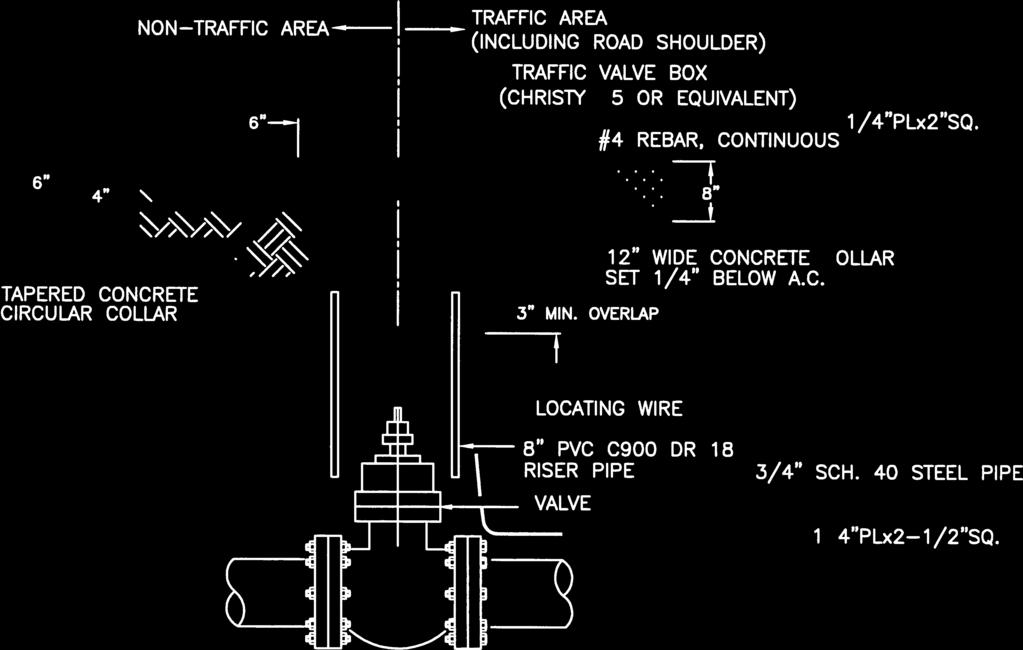


185
COUNTY OF YUBA DEPARTMENT OF PUBLIC WORKS IMPROVEMENT STANDARDS
 COUNTY OF YUBA DEPARTMENT OF PUBLIC WORKS IMPROVEMENT STANDARDS TABLE OF CONTENTS SECTION 1 PURPOSE AND DEFINITIONS 1.1 PURPOSE:... 1 1.2 DEFINITIONS:... 1 SECTION 2 GENERAL REQUIREMENTS 2.1 PLANS BY AN
Chapter 3: Permit Procedures and Requirements
 Chapter 1: General Provisions 1 1 Short Title 1 2 Jurisdiction 1 3 Amendments and Revisions 1 4 Enforcement Responsibility 1 5 Review Process 1 6 Prior Approval 1 7 Relationship to Other Standards 1 8
CITY OF LA QUINTA GENERAL NOTES GENERAL NOTES
 CITY OF LA QUINTA GENERAL NOTES GENERAL NOTES 1. ALL WORK SHALL BE DONE IN ACCORDANCE WITH THE LATEST EDITION OF THE STANDARD PLANS OF THE CITY OF LA QUINTA, THE LATEST EDITION OF THE STANDARD SPECIFICATIONS
COUNTY OF SUTTER ENCROACHMENT PERMIT
 COUNTY OF SUTTER ENCROACHMENT PERMIT PERMIT No. Development Services Dept. Engineering Division 1130 Civic Center Blvd Yuba City, CA 95993 (530) 822-7400 Hours: 8 AM - 5 PM Upon completion, submit application
APPLICATION FOR PUBLIC INFRASTRUCTURE PERMIT
 APPLICATION FOR PUBLIC INFRASTRUCTURE PERMIT Engineering Division 550 Landa Street New Braunfels, Texas 78130 (830) 221-4020 1. Subdivision Plat Name: Location Description/ Nearest Intersection: Acreage:
A.1 WATER SYSTEM PLAN SUBMITTAL PROCEDURES AND GENERAL REQUIREMENTS
 PC Plan Submittal and Review A.1 WATER SYSTEM PLAN SUBMITTAL PROCEDURES AND GENERAL REQUIREMENTS All plans for water main extensions, improvements and modifications shall be submitted to the District manager.
TOWN OF MANCHESTER PLANNING AND ZONING COMMISSION Subdivision Application Minimum Submission Requirements
 TOWN OF MANCHESTER PLANNING AND ZONING COMMISSION Subdivision Application Minimum Submission Requirements This checklist is to be completed and submitted with all Subdivision Applications. The Town reserves
Construction Requirements for Installation of Utilities in the Public Right-of-way of McPherson County, Kansas October 2011
 Construction Requirements for Installation of Utilities in the Public Right-of-way of McPherson County, Kansas October 2011 General Provisions and Specifications - These provisions and specifications shall
INSPECTION AND ACCEPTANCE FOR MAINTENANCE
 Inspection and Acceptance For Maintenance Page 1 (Last revised 6/29/10) INSPECTION AND ACCEPTANCE FOR MAINTENANCE SELECTED LINKS TO SECTIONS WITHIN THIS SPECIFICATION Acceptance Sewer As Built Drwg Example
PLANNING AND ZONING COMMISSION APPLICATION FOR IMPROVEMENT PLAT APPROVAL
 PLANNING AND ZONING COMMISSION APPLICATION FOR IMPROVEMENT PLAT APPROVAL Date Submitted: Project Number: CITY OF ALEXANDRIA 8236 WEST MAIN STREET ALEXANDRIA, KY 41001 (859) 635-4125 FAX (859) 635-4127
EXCAVATION WORK IN PUBLIC RIGHT-OF-WAY GENERAL NOTES
 CITY OF SANTA MONICA Department of Public Works Civil Engineering Division 1685 Main, Room 116 Santa Monica, CA 90401 Tel: (310) 458-2240 or (310) 458-8737 EXCAVATION WORK IN PUBLIC RIGHT-OF-WAY GENERAL
GENERAL NOTES REQUIRED NOTES ON ALL PLANS
 GENERAL NOTES REQUIRED NOTES ON ALL PLANS ALL MATERIALS, WORKMANSHIP AND CONSTRUCTION SHALL CONFORM TO THE CURRENT CITY OF SANTA ROSA DESIGN AND CONSTRICTIOIN STANDARDS AND CONSTRUCTION SPECIFICATIONS
Construction Documents Checklist
 Construction Documents Checklist The following must be completed prior to final approval of site development plans (Construction Documents) by the Town: Final Drainage Report signed by engineer-of-record
PUBLIC WORKS DEPARTMENT GENERAL NOTES
 PUBLIC WORKS DEPARTMENT GENERAL NOTES 1. All construction shall be in strict accordance with the standards of the City of Southlake and governed by the North Central Texas Council of Government's Standard
Appendix 3. POLICY & PROCEDURE No
 DEPARTMENT OF PUBLIC WORKS DIVISION: ENGINEERING SERVICES SECTION: ADMINISTRATIVE PAGE NO: 1 OF 10 REVISION NO: 3 DATE: 1995 05 01 ESTABLISHED: 1986 03 03 Appendix 3 POLICY & PROCEDURE No. 2.3.1-020 TITLE:
CONSTRUCTION PLAN CHECKLIST
 CONSTRUCTION PLAN CHECKLIST The design engineer is responsible for ensuring that plans submitted for city review are in accordance with this checklist. It is requested that the executed checklist be submitted
BONDING REQUIREMENTS AND PROCEDURES
 Town of Apex Development Services 73 Hunter Street, 3 rd Floor Apex, NC 27502 (919) 249-3394 BONDING REQUIREMENTS AND PROCEDURES ORDINANCE RATIFYING THE REQUIREMENT FOR BONDING: (From the Unified Development
APPENDIX B STANDARD CONSTRUCTION DRAWING NOTES
 APPENDIX B STANDARD CONSTRUCTION DRAWING NOTES B-1 General Notes: SACWSD Standard Construction Drawing Notes 1. No work shall begin on any water or wastewater construction project until the construction
SECTION 13 - EXISTING FACILITIES TABLE OF CONTENTS
 SECTION 13 - EXISTING FACILITIES TABLE OF CONTENTS Section Page 13-1 GENERAL... 13.1 13-1.01 Preservation of Property... 13.1 13-1.02 Overloading, Pavement Protection & Repair... 13.1 13-2 REMOVING EXISTING
PLANS. All plans shall be submitted on 24 x 36 sheets
 PLANS All plans shall be submitted on 24 x 36 sheets PLANS FOR CONSTRUCTION - (STICKY BACKS NOT ACCEPTABLE) Cover Sheet The first sheet of the plan and profile will not be accepted as a cover sheet. The
CUYAHOGA COUNTY DEPARTMENT OF PUBLIC WORKS CUYAHOGA COUNTY ENGINEER TOWNSHIP SUBDIVISION STREET DESIGN STANDARDS AND IMPROVEMENT PLAN REQUIREMENTS
 CUYAHOGA COUNTY DEPARTMENT OF PUBLIC WORKS CUYAHOGA COUNTY ENGINEER TOWNSHIP SUBDIVISION STREET DESIGN STANDARDS AND IMPROVEMENT PLAN REQUIREMENTS November 25, 2013 Table of Contents Cuyahoga County Engineer's
Index. Composition and Order of Plan Set. Utility Plan... 5
 City of Des Plaines Public Works and Engineering Department Revised-October 5, 2012 Index Composition and Order of Plan Set Title Page Number Cover Sheet... 1 Requirements for Site Development... 2 Grading
SECTION 18 - EARTHWORK TABLE OF CONTENTS
 SECTION 18 - EARTHWORK TABLE OF CONTENTS Section Page 18-1 GENERAL... 18-2 18-2 ROADWAY EXCAVATION... 18-2 18-2.01 General... 18-2 18-2.02 Unsuitable Roadway Excavation and Backfill... 18-2 18-2.03 Surplus
SECTION SITE GRADING. Part 1 - General Work Included Related Requirements Reference Standards...
 SECTION 02210 - SITE GRADING CONTENTS: Part 1 - General... 1 1.01 Work Included... 1 1.02 Related Requirements... 1 1.03 Reference Standards... 1 1.04 Quality Assurance... 1 1.05 Measurement and Payment...
STANDARD GRADING AND SOIL EROSION & SEDIMENT CONTROL PLAN FOR SINGLE LOT SINGLE FAMILY RESIDENTIAL CONSTRUCTION AND MINOR EARTH DISTURBANCES
 DIVISION OF ENGINEERING & CONSTRUCTION MANAGEMENT PLAN REVIEW DEPARTMENT WASHINGTON COUNTY SOIL CONSERVATION DISTRICT 1260 Maryland Avenue, Suite 101 Hagerstown, MD 21740 Telephone: (301) 797-6821, Ext.
B-PERMIT PLAN CHECK MANUAL
 B-PERMIT PLAN CHECK MANUAL 11. PLAN SHEETS AND NOTES Preformatted B-Permit plans sheets can be downloaded from the internet on the Bureau of Engineering s website. The Plan sheets can be found under the
CITY OF ASTORIA PUBLIC WORKS ENGINEERING DIVISION ENGINEERING DESIGN STANDARDS FOR IN-FILL DEVELOPMENT
 CITY OF ASTORIA PUBLIC WORKS ENGINEERING DIVISION ENGINEERING DESIGN STANDARDS FOR IN-FILL DEVELOPMENT Adopted by City Council: May 21, 2007 X:\General Eng\DESIGN STANDARDS\Engineering Design Standards
SECTION EARTHWORK; EXCAVATION, FILLING AND GRADING. A. Excavating soil and other material for surface improvements.
 SECTION 31 20 00 PART 1 - GENERAL 1.1 SECTION INCLUDES A. Excavating soil and other material for surface improvements. B. Excavating soil and other material for drainage basins. C. Placing fill. D. Compaction
SECTION 18 - EARTHWORK TABLE OF CONTENTS
 SECTION 18 - EARTHWORK TABLE OF CONTENTS Section Page 18-1 GENERAL... 18.1 18-2 ROADWAY EXCAVATION... 18.1 18-2.01 General... 18.1 18-2.02 Unsuitable Roadway Excavation and Backfill... 18.1 18-2.03 Surplus
York County Engineering Department Roadway Inspection Requirements
 York County Engineering Department Roadway Inspection Requirements The following is a list, in order, of the roadway inspections that are required to be passed by York County before a subdivision can receive
SECTION 3 DRAINAGE. 3-1 General. 3-2 Drainage Ordinances and Legal Requirements
 SECTION 3 DRAINAGE 3-1 General All Drainage plans for proposed development shall be prepared by a Professional Engineer registered in Virginia, except as noted below. Further, their seal and signature
ZONING ORDINANCE FOR THE ZONED UNINCORPORATED AREAS ARTICLE 1500 OF PUTNAM COUNTY, WEST VIRGINIA Page 149 ARTICLE 1500 DRAINAGE AND STORM SEWERS
 OF PUTNAM COUNTY, WEST VIRGINIA Page 149 ARTICLE 1500 DRAINAGE AND STORM SEWERS 1500.01 GENERAL REQUIREMENTS 1500.02 NATURE OF STORM WATER FACILITIES 1500.03 DRAINAGE EASEMENTS 1500.04 STORM WATER MANAGEMENT
OPERATING POLICY MANUAL
 Page 1 of 7 Section 1. PURPOSE This policy is to explain the review process that the Bedford Regional Water Authority ( Authority ) utilizes for water and sewer developer projects planned within the service
UNIFORM DESIGN AND CONSTRUCTION STANDARDS FOR EXTENDING WATER DISTRIBUTION SYSTEMS SECTION 2 DESIGN STANDARDS
 UNIFORM DESIGN AND CONSTRUCTION STANDARDS FOR EXTENDING WATER DISTRIBUTION SYSTEMS SECTION 2 DESIGN STANDARDS DESIGN STANDARDS SECTION 2 INDEX ITEM DESCRIPTION 2.00 GENERAL STATEMENT 2.01 WATER DISTRIBUTION
SECTION CONSTRUCTION SERVICES
 SECTION 01100 CONSTRUCTION SERVICES PART 1 GENERAL 1.01 - Section Includes A. Mobilization. B. Construction Surveys. C. Record Documents. 1.02 Description Of Work A. Mobilization: includes the preparatory
York County Engineering Department Roadway Inspection Requirements
 York County Engineering Department Roadway Inspection Requirements The following is a list, in order, of the roadway inspections that are required to be passed by York County before a subdivision can receive
APPENDIX A DESIGN SPECIFICATIONS FOR NEW ROAD CONSTRUCTION
 APPENDIX A DESIGN SPECIFICATIONS FOR NEW ROAD CONSTRUCTION 1. GENERAL SPECIFICATIONS 1.1 Specifications: Plans shall be prepared by a professionally registered engineer duly authorized to conduct business
Ordinance No Lot Surface Drainage
 Ordinance No. 35-2008 - Lot Surface Drainage The Township has adopted a new Lot Surface Drainage Ordinance which amends Chapter 170, Article IX, Subdivision and Site Plan Review by adding a new Section
CITY OF HOMESTEAD Utility Rights-of-Way Use Permit Application
 CITY OF HOMESTEAD Utility Rights-of-Way Use Permit Application Good for 90 days from the Date Issued This permit is only required if the work location is owned or controlled by the City of Homestead and
SECTION 18 - EARTHWORK TABLE OF CONTENTS
 SECTION 18 - EARTHWORK TABLE OF CONTENTS Section Page 18-1 GENERAL...18.1 18-2 ROADWAY EXCAVATION...18.1 18-2.01 General...18.1 18-2.02 Unsuitable Roadway Excavation and Backfill...18.1 18-2.03 Surplus
APPLICANT any person who makes application for a permit. BOROUGH Borough of Elizabethtown, Lancaster County, Pennsylvania.
 CHAPTER 21 PART 2 TUNNELING AND EXCAVATIONS 201. Definitions. The following words and phrases, when used in this Part, shall have the meanings ascribed to them in this 201, except in those instances where
ASPHALT CONCRETE COLD PLANING THROUGH DECEMBER 2017
 FOR ASPHALT CONCRETE COLD PLANING THROUGH DECEMBER 2017 Date Prepared: March 2017 TABLE OF CONTENTS SECTION 1 GENERAL... SP-1 1-1.01 Terms and Definitions... SP-1 SECTION 2 BIDDING... SP-1 2-1.01 General...
SECTION CS-2. TRENCH EXCAVATION CONSTRUCTION STANDARDS
 SECTION CS-2. TRENCH EXCAVATION CONSTRUCTION STANDARDS CS-2-01. GENERAL: Trench excavation shall conform with the City Standard Specifications. In general a trench is defined as an excavation in which
SECTION MAINTENANCE OF EXISTING CONDITIONS
 SECTION 02 01 00 MAINTENANCE OF EXISTING CONDITIONS PART 1 GENERAL 1.1 GENERAL A. The CONTRACTOR shall protect all existing utilities and improvements not designated for removal and shall restore damaged
7.00 INTRODUCTION... 1
 SITE PLANS, REZONING, LAND DIVISION AND CONDOMINIUM SECTION 7 GENERAL REQUIREMENTS INDEX Page 7.00 INTRODUCTION... 1 7.01 SITE GRADING AND MECHANICAL PLANS... 2 7.01.01 Submission Procedures... 2 7.01.02
SECTION GENERAL EXCAVATION
 02210-1 of 11 SECTION 02210 GENERAL EXCAVATION 02210.01 GENERAL A. Description 1. General excavation shall include but not necessarily be limited to, excavation and grading for general site work, roadways,
CITY OF SOUTH LAKE TAHOE APPLICATION FOR ENCROACHMENT, EXCAVATION and GRADING WITHIN THE CITY RIGHT OF WAY
 CITY OF SOUTH LAKE TAHOE APPLICATION FOR ENCROACHMENT, EXCAVATION and GRADING WITHIN THE CITY RIGHT OF WAY The Right-of-Way Encroachment, Excavation & Grading Permit issued by the Public Works Department
SECTION TRAFFIC REGULATIONS
 PART 1 GENERAL 1.1 DESCRIPTION A. Traffic Control permits, notifications, mobilization, temporary signs, barriers, lights, flagging personnel, striping, markings, and demobilization and removal. 1.2 RELATED
SUBDIVISION CHECKLIST. Subdivision Name. Prior To Review. Preliminary plan approved by Planning Commission / Council as required.
 SUBDIVISION CHECKLIST Subdivision Name Account Number Review Engineer Prior To Review Preliminary plan approved by Planning Commission / Council as required. Review fee paid. Statement of Responsibility
Grading Requirements City of Red Bluff Table of Contents. Introduction and Scope...1. Permit Exempt Work...1. Permit Application Submittals...
 Table of Contents General Notes Introduction and Scope...1 Permit Exempt Work...1 Permit Application Submittals...2 Other Procedural Requirements...3 Exhibit A - Grading Plans...4 Exhibit B - Milestones
SECTION 12 STANDARDS FOR CONSTRUCTION PLANS AND SPECIFICATIONS
 SECTION 12 STANDARDS FOR CONSTRUCTION PLANS AND SPECIFICATIONS 12.1 The subdivider shall construct and install the improvements in accordance with the County's Standards for Construction Plans and Specifications
DEVELOPMENT CODE REVISIONS CHAPTER 6 1 CASE # RESO # SECTION/DESCRIPTION DATE , 6206, 6207, /09/03
 DEVELOPMENT CODE REVISIONS CHAPTER 6 1 CASE # RESO # SECTION/DESCRIPTION DATE 03-005 03-45 6102.01, 6206, 6207, 6402 06/09/03 03-061 03-71 Deleted berm regs (moved to Chapter 3) 9/8/03 04-077 07-44 Comprehensive
MINIMUM REQUIREMENTS FOR CONSTRUCTION PLANS, GRADING AND/OR DRAINAGE PLANS, LOW IMPACT DEVELOPMENT PLANS, AND WATER EFFICIENT LANDSCAPE PLANS
 Planning and Community Preservation Department Public Works Department 232 West Sierra Madre Boulevard Sierra Madre, CA 91024 (626)355-7135 MINIMUM REQUIREMENTS FOR CONSTRUCTION PLANS, GRADING AND/OR DRAINAGE
CONSTRUCTION SURVEY. Construction survey includes personnel, equipment, and supplies required for, but not limited to, the following:
 CONSTRUCTION SURVEY PART 1 - GENERAL 1.01 SECTION INCLUDES Construction survey includes personnel, equipment, and supplies required for, but not limited to, the following: A. Construction Survey: 1. Project
ROADWAY DESIGN AND CONSTRUCTION STANDARDS
 ROADWAY DESIGN AND CONSTRUCTION STANDARDS Adopted: 1990 Amended: 1994 2003 2011 2013 ROADWAY DESIGN AND CONSTRUCTION STANDARDS ORIGINALLY ADOPTED IN 1990 Resolution No. R-990-046 OFFICIALLY AMENDED IN
GRADING & DRAINAGE PERMIT SOIL EROSION AND SEDIMENTATION CONTROL PERMIT PROGRAM OVERVIEW
 GRADING & DRAINAGE PERMIT SOIL EROSION AND SEDIMENTATION CONTROL PERMIT PROGRAM OVERVIEW Chapter 8 Building and Building Regulations, Article XIII Grading and Drainage and Article XV Soil Erosion and Sedimentation
SITE SPECIFIC GRADING PLAN FOR CONTIGUOUS SINGLE LOT SINGLE FAMILY RESIDENTIAL CONSTRUCTION WITH PREVIOUSLY APPROVED PRELIMINARY PLAT (FORM 2)
") WASHINGTON COUNTY DIVISION OF PLAN REVIEW AND PERMITTING 80 West Baltimore Street Hagerstown, Maryland 21740-6003 Telephone: (240) 313-2460 FAX: (240) 313-2461 Hearing Impaired call 7-1-1 for Maryland
WASHINGTON COUNTY DIVISION OF PLAN REVIEW AND PERMITTING 80 West Baltimore Street Hagerstown, Maryland 21740-6003 Telephone: (240) 313-2460 FAX: (240) 313-2461 Hearing Impaired call 7-1-1 for Maryland
Will County Site Development Permit Submittal Checklist TAB 1 PROJECT OVERVIEW
 Applicant: Reviewer: Permit No.: The following tables contain a checklist of the requirements before a review for a Site Development Permit submittal will be accepted. Not all requirements pertain to every
CITY OF JACKSON IMPROVEMENT STANDARDS RESOLUTION NO.
 CITY OF JACKSON IMPROVEMENT STANDARDS RESOLUTION NO. April 2012 TABLE OF CONTENTS 1.00 PURPOSE AND INTENT... 1 2.00 GENERAL REQUIREMENTS... 3 2.01 PLANS AND SPECIFICATIONS REQUIRED... 3 2.02 STANDARD SPECIFICATIONS...
PLAN CHECK GUIDELINES MULTI-FAMILY/COMMERCIAL
 o PUBLIC WORKS DEPARTMENT PLAN CHECK GUIDELINES MULTI-FAMILY/COMMERCIAL CIVIL ENGINEERING AND ARCHITECTURE 1. Offsite Improvements - Civil Engineering drawings may be required to show the following: Replacement
DESIGN CRITERIA & CONSTRUCTION REGULATIONS
 DESIGN CRITERIA & CONSTRUCTION REGULATIONS APRIL 2004 BY: TST, INC. CONSULTING ENGINEERS FORWARD PURPOSE OF THIS MANUAL The Town of Johnstown has prepared this manual to provide guidance to engineers and
ARTICLE 700 LARGE SCALE DEVELOPMENTS
 ARTICLE 700 LARGE SCALE DEVELOPMENTS SEC. 700.1 APPLICABILITY A development plan shall be submitted to the Bentonville Planning Commission for all developments or building construction regardless of zone
CITY OF SAFETY HARBOR 750 MAIN STREET, SAFETY HARBOR, FLORIDA PHONE: 727/ FAX: 727/
 CITY OF SAFETY HARBOR 750 MAIN STREET, SAFETY HARBOR, FLORIDA 34695 PHONE: 727/724-1555 FAX: 727/724-1566 RIGHT-OF-WAY / EASEMENT USE PERMIT DATE SUBMITTED: EXPIRATION DATE: Submit the following to the
CITY OF MERIDIAN LAND DEVELOPMENT SERVICES SUBDIVISION PLAN REVIEW CHECK LIST
 Project Name: Hearing Date: Reviewer: Date of Review: # OK NEED N/A General Plan Design All documents, design standards, specifications, and forms should be taken from the website each time they are used
MAIN EXTENSIONS: WATER & SEWER. 7.1 General Provisions
 SECTION 7 MAIN EXTENSIONS: WATER & SEWER 7.1 General Provisions Persons proposing subdivisions or developments requiring a main extension for sewer or water service shall prepare applications described
STORMWATER AND EROSION CONTROL PERMIT
 STORMWATER MANAGEMENT AND EROSION CONTROL PERMIT INSTRUCTIONS AND INFORMATION Any project that involves the disturbance of ANY quantity of land requires the applicant to receive approval for the project
STORMWATER AND EROSION CONTROL PERMIT
 STORMWATER MANAGEMENT AND EROSION CONTROL PERMIT INSTRUCTIONS AND INFORMATION Any project that involves the disturbance of ANY quantity of land requires the applicant to receive approval for the project
Title 15 BUILDINGS AND CONSTRUCTION
 Title 15 BUILDINGS AND CONSTRUCTION Chapters: 15.04 International Codes Adopted 15.08 Building Permits 15.12 Movement of Buildings Chapter 15.04 INTERNATIONAL CODE COMMISSION CODES Sections: 15.04.010
District No.: Applicant: Type of Work:
 Fee: Permit No.: District No.: Applicant: Type of Work: FOR DEPARTMENT USE ONLY APPLICATION AND ANNUAL PERMIT FOR TELECOMMUNICATION OCCUPANCY OF NEVADA DEPARTMENT OF TRANSPORTATION RIGHT-OF-WAY (Under
GRAYSON COUNTY POLICY, PROCEDURES AND SPECIFICATIONS OF GRAYSON COUNTY, TEXAS FOR THE INSTALLATION OF DRIVEWAY
 GRAYSON COUNTY POLICY, PROCEDURES AND SPECIFICATIONS OF GRAYSON COUNTY, TEXAS FOR THE INSTALLATION OF DRIVEWAY CULVERTS, ROAD BORES, USE OF HEAVY EQUIPMENT AND UTILITY LINES WITHIN GRAYSON COUNTY ROAD
CITY OF TACOMA RIGHT-OF-WAY RESTORATION POLICY. Guidance on restoration of City Rights-of-Way
 CITY OF TACOMA RIGHT-OF-WAY RESTORATION POLICY Guidance on restoration of City Rights-of-Way Public Works Department Directors Office 747 Market Street Suite 408 Tacoma, WA 98402 253-591-5525 Right-of-Way
CHAPTER 7 - INFRASTRUCTURE INSPECTION AND ACCEPTANCE... 2
 CHAPTER 7 - INFRASTRUCTURE INSPECTION AND ACCEPTANCE... 2 7.1. GENERAL.... 2 7.1.1. Inspection Restriction Dates.... 2 7.1.2. Complete Improvements.... 2 7.1.3. Public Improvements.... 2 7.1.4. Warranty
It is the CONTRACTORS RESPONSIBILITY to use OSHA approved shoring
 PERMIT# EXCAVATION/RIGHT OF WAY PERMIT ATE: NOTE: No permit shall be issued \vithout CURRENT Montana Contractors License, Insurance and Bonding on file with the Public Works epartment. It is the CONTRACTORS
CHAPTER 5 WATER SYSTEM DESIGN STANDARDS
 CHAPTER 5 WATER SYSTEM DESIGN STANDARDS TABLE OF CONTENTS CHAPTER 5 WATER SYSTEM DESIGN STANDARDS 5.00 Objective Page 1 5.01 Additional Referenced Standards Page 1 5.02 Special Design Problems Page 2 5.03
APPLICATION FOR A SITE CONSTRUCTION PERMIT
 CITY OF KLAMATH FALLS PUBLIC WORKS ENGINEERING 226 S. 5 th St., Klamath Falls, OR 97601 Phone (541) 883-5368 Fax (541) 883-5287 APPLICATION FOR A SITE CONSTRUCTION PERMIT For City Use Only: APPLICATION
REGIONAL CONSTRUCTION STANDARDS
 REGIONAL CONSTRUCTION STANDARDS SIXTH EDITION Publication Update 6.5 (Full Committee Approved Proposed Revision 6.5 Storm Sewer Joint Wrap - Section 302 As Publication Update 6.5) March 27, 2018 Copyright
TOWN of LAKESHORE SUBDIVISION DEVELOPMENT PLAN CHECKLIST
 Project Name: Project Location: Date Submitted: TOWN of LAKESHORE SUBDIVISION DEVELOPMENT PLAN CHECKLIST Last Revised January 31, 2014 Name Phone Number E-mail Address Owner: Contractor/ Engineer: ( )
CITY OF PANAMA CITY BEACH Utilities Administration & Engineering Offices 116 South Arnold Road Panama City Beach, FL 32413
 Page: 1 of 5 CITY OF PANAMA CITY BEACH Utilities Administration & Engineering Offices 116 South Arnold Road Panama City Beach, FL 32413 COMMERCIAL/RESIDENTIAL UTILITY PLAN COMPLETENESS CHECK LIST Updated
EXHIBIT A FEE SCHEDULE
 EXHIBIT A FEE SCHEDULE PERMIT FEE WORKSHEET INSTRUCTIONS: Each application for a new permit or change in status shall be accompanied by the appropriate fee as indicated below. NO PERMIT APPLICATION WILL
Development Advisory - 40 March 21, 2018
 Development Advisory - 40 March 21, 2018 Single Family Lot Grading Requirement The City of Chesapeake has policies that distribute the responsibility for lot grading between the developer and the builder.
Construction Specification for General Excavation
 Engineering & Construction Services Division Standard Specifications for Road Works TS 2.10 September 2018 for General Excavation Table of Contents TS 2.10.01 SCOPE... 2 TS 2.10.02 REFERENCES... 2 TS 2.10.03
STAFF REPORT CITY OF SOLANA BEACH
 7-13-16 Mtg Item D.1. Updated Report #1 STAFF REPORT CITY OF SOLANA BEACH TO: Honorable Mayor and City Councilmembers FROM: Gregory Wade, City Manager MEETING DATE: ORIGINATING DEPT: Community Development
LAGRANGE TOWNSHIP 353 South center street p.o. box 565 lagrange ohio 44050
 LAGRANGE TOWNSHIP 353 South center street p.o. box 565 lagrange ohio 44050 Resolution 2004-5 Resolution of the Board of Trustees of LaGrange Township, Lorain County, Ohio, adopting general rules and regulations
(ITEMS APPLICABLE TO THIS PROJECT MARKED WITH "X")
") Development Services Planning Division 150 N. Lakeshore Drive Ocoee, FL 34761 Phone: 407.905.3157 Fax: 407.905.3158 Received Date Office Use Only (ITEMS APPLICABLE TO THIS PROJECT MARKED WITH "X") DATE:
Development Services Planning Division 150 N. Lakeshore Drive Ocoee, FL 34761 Phone: 407.905.3157 Fax: 407.905.3158 Received Date Office Use Only (ITEMS APPLICABLE TO THIS PROJECT MARKED WITH "X") DATE:
REQUIREMENTS FOR WORK WITHIN ROAD RIGHTS-OF-WAY IN UNION COUNTY
 REQUIREMENTS FOR WORK WITHIN ROAD RIGHTS-OF-WAY IN UNION COUNTY The requirements contained herein are established to provide for orderly and systematic use of the county road rights-of-way within Union
Highway / Utility Guide
 Oregon Department of Transportation Highway Division Right of Way Section Highway / Utility Guide Railroad & Utilities Unit Right of Way Section STATEMENT OF PURPOSE It is important to understand that
CHAPTER 2. Restricted Residential ½ Street** Design Speed 25 MPH 25 MPH 25 MPH 25 MPH 40 MPH 50 MPH 55 MPH
 CHAPTER 2 201 ROADS 201.1 General This section is to assist the designer in determining what is needed for the design of roads in public rights-of-way. For these standards, the terms used are: Restricted
1.01 GENERAL. l.02 PIPELINE TRENCH EXCAVATION PIPELINES AND STRUCTURES REVISION: SECTION 1 PAGE : 1-1
 1.01 GENERAL A. The Contractor shall perform all excavation, backfilling, grubbing and grading required for construction and installation of pipelines, structures and appurtenances. Excavation shall include
PUBLIC AND PRIVATE IMPROVEMENTS CODE OF THE TOWNSHIP OF UPPER ST. CLAIR
 99.0 PUBLIC AND PRIVATE IMPROVEMENTS CODE 99.0 PUBLIC AND PRIVATE IMPROVEMENTS CODE OF THE TOWNSHIP OF UPPER ST. CLAIR TABLE OF CONTENTS 99.1. ADMINISTRATION AND GENERAL REGULATIONS...2 99.1.1. Title...2
T a b l e o f C o n t e n t s
 C i t y o f G l a d s t o n e P u b l i c W o r k s D e s i g n S t a n d a r d s T a b l e o f C o n t e n t s SECTION THREE SANITARY SEWER REQUIREMENTS... 1 3.0000 SANITARY SEWERS... 1 3.0010 General
STREET IMPROVEMENTS (Refer to Title 18, chapter entitled "STREETS" of the Layton Municipal Code.)
") STREET IMPROVEMENTS (Refer to Title 18, chapter 18.24 entitled "STREETS" of the Layton Municipal Code.) I. Street widths STREET TYPE (ALL MEASUREMENTS IN FEET) ROW WIDTH LAYTON CITY STANDARD STREET SECTIONS
STREET IMPROVEMENTS (Refer to Title 18, chapter 18.24 entitled "STREETS" of the Layton Municipal Code.) I. Street widths STREET TYPE (ALL MEASUREMENTS IN FEET) ROW WIDTH LAYTON CITY STANDARD STREET SECTIONS
General Rules and Regulations
 General Rules and Regulations City of Hamilton, Ohio Sanitary Sewer Collection and Treatment Revised December 23, 2016 Page 1 of 13 To Our Customers, Sanitary Sewer Collection and Treatment Department
SECTION ASPHALT PAVING AND SURFACING
 SECTION 02500 ASPHALT PAVING AND SURFACING PART 1 - GENERAL 1.01 WORK INCLUDED A. Traffic control as required to divert vehicular and pedestrian traffic around construction. B. Spreading and compacting
SECTION 14 - RESTORATION OF SURFACES TABLE OF CONTENTS
 SECTION 14 - RESTORATION OF SURFACES TABLE OF CONTENTS Section Page SECTION 14 RESTORATION OF SURFACES... 14.1 14-1 GENERAL... 14.1 14-2 PRIVATE ROADS... 14.1 14-3 STREETS AND PARKING LOTS... 14.1 14-3.01
APPLICATION FOR RIGHT OF WAY PERMIT
 City of Danville Department of Engineering & Urban Services APPLICATION FOR RIGHT OF WAY PERMIT PROJECT LOCATION: CONTRACTOR S BUSINESS NAME: CONTRACTOR'S ADDRESS: CONTRACTOR'S PHONE: OWNER S NAME: OWNER
N.J.A.C. 19: This file includes all Regulations adopted and published through the New Jersey Register, Vol. 50 No. 1, January 2, 2018
 N.J.A.C. 19:66-8.1 19:66-8.1 Purpose (a) This subchapter serves the following purposes: 1. To provide for the comprehensive and orderly development of the district in accordance with the Tourism District
SPECIFICATIONS - DETAILED PROVISIONS Section Site Grading C O N T E N T S
 SPECIFICATIONS - DETAILED PROVISIONS Section 02210 - Site Grading C O N T E N T S PART 1 - GENERAL... 1 1.01 REQUIREMENT... 1 1.02 STRUCTURE PROTECTION... 2 1.03 JOB CONDITIONS... 3 PART 2 - PRODUCTS...
TOWN OF HOLLIS, NEW HAMPSHIRE
 TOWN OF HOLLIS, NEW HAMPSHIRE ROAD and DRIVEWAY SPECIFICATIONS APPENDIX (Adopted 10/7/08) APPENDIX A A. Road Design Standards 1. Pavement and drainage facilities, curbs and sidewalks, when required, shall