GEO-flow Pipe Leaching System Specifications & Features. Design & Installation Manual Maine
|
|
|
- Melvin Sparks
- 5 years ago
- Views:
Transcription


1 GEO-flow Pipe Leaching Specifications & Features Design & Installation Manual Maine 1
2 Contents I. Introduction 3 II. The GEO-flow Pipe Leaching 4 III. GEO-flow Pipe Leaching Specification 5 IV. GEO-flow Pipe Leaching Schematic 5 V. Basic Design Considerations 6 VI. Maine State-Specific Considerations 6 VII. Sizing the GEO-flow Pipe Leaching 7 VIII. Installation Instructions 8 IX. Configurations 9-16 X. Appendix I 17 2
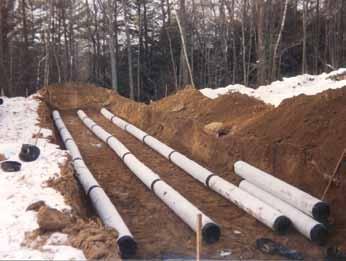
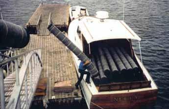
3 I. Introduction The purpose of this manual is to provide the minimum design and installation information for the use of the ADS GEO-flow Pipe Leaching in the State of Maine. Any exceptions or changes to the design or procedures must be confirmed by ADS, Inc. Any revised version of this manual supersedes all previous versions. This manual is to be used in conjunction with the Maine Subsurface Waste Water Disposal Rules and other State or local regulations regarding septic systems. This manual provides a brief description of the GEO-flow Pipe Leaching and its applications in Maine. For more information, or for answers to questions or concerns, please call ADS at our Northeast Zone office at the number listed below, or contact your local ADS representative. The GEO-flow Pipe system is an advanced alternative to the stone and pipe components of a conventional effluent disposal system. The GEO-flow Pipe product is fabricated at our plants using ADS manufactured corrugated polyethylene pipe. This large-diameter pipe is encased in a symmetrical polypropylene grid, which is then wrapped in a specifically designed geotextile. This patented design, when installed in 6 inches of specified system sand, creates a system that is significantly more efficient than conventional pipe and stone. GEO-flow Pipe is lightweight, and does not require the use of stone. Therefore, it may be delivered to and constructed in areas where conventional pipe and stone systems would be difficult to install. GEO-flow Pipe has been used successfully for more than 20 years for both residential and commercial installations throughout Maine and New Hampshire. designers can specify GEO-flow Pipe with confidence in the knowledge that the GEO-flow Pipe product they install in each and every system will be fully backed by ADS. ADS/Hancor, Inc., 58 Wyoming Street, Ludlow, MA

4 II. THE GEO-flow PIPE LEACHING SYSTEM Each GEO-flow Pipe Leaching is comprised of the following components: Complete 10 GEO-flow pipe sections adapters End caps Couplers sand 1. GEO-flow Pipe Sections GEO-flow Pipe sections come in 10-foot lengths. Each section is comprised of the following: ADS/Hancor manufactured corrugated high-density polyethylene pipe. This pipe is perforated to allow for effluent to pass through its sidewalls easily and at varying heights. This pipe is encased in a: Symmetrical polypropylene grid, which is wrapped in a: Specially designed, non-woven plastic geotextile fabric. The GEO-flow Pipe sections function in a number of ways. The geotextile fabric establishes a distinct surface at which bacterial growth and activity will take place. This material will restrict the flow of effluent leaving the corrugated pipe, and biomat will naturally occur on its surface as a result. In addition, the large-diameter corrugated pipe creates dispersal medium where effluent introduced into the system is constantly changing elevations. This changing of elevations encourages and enhances the bacterial activity within the biomat, thereby maximizing its function. The large diameter pipe also serves as a repository for suspended solids that may inadvertently exit the septic tank. Finally, the polypropylene grid between the pipe and the fabric creates a substrate for bacterial communities while aiding in the distribution of effluent around the entire circumference of the pipe. 2. Adapters adapters are end caps fitted with a 4-inch offset hole at the 12 o clock position. 5. All GEO-flow Pipe Leaching s installed in Maine require a minimum of six inches (6 ) of system sand surrounding the entire circumference of the pipe. : sand shall meet CMR 241 Table 11A backfill requirements. Surrounding Backfill Material: Material around the remainder of the system shall CMR 241 requirements. Bed Material: In-ground systems which slope 10% or less require the system sand area to extend a minimum of one foot (1 ) around the perimeter of the GEO-flow pipe bed. Fill Extensions: Raised systems that include a slope of 10% or less require an additional three-foot (3 ) extensions on each side (including system sand, surrounding sand, and topsoil) before tapering. Raised systems that include a slope of greater than 10% require three-foot (3 ) extensions on three (3) sides and a five-foot (5 ) extension on the down slope side before tapering. Tapering shall be 3:1 or less. 3. End caps End caps are molded to fit snugly on the end of any GEO-flow Pipe section to close the line. 4. Couplers Internal couplers fit within the ends of two GEO-flow Pipe sections to create a GEO-flow pipeline. 4
5 III. GEO-FLOW PIPE LEACHING SYSTEM SPECIFICATIONS Scope This specification describes GEO-flow available in 10-inch (250 mm) inside diameter pipe for use in onsite waste disposal applications in Maine. Pipe Requirements ADS GEO-flow pipe shall meet the requirements of ASTM F667. It shall have a corrugated interior and exterior. There shall be eight 7/16 inch (9.5 mm) holes evenly spaced 45 degrees apart per corrugation continuing the full length of the pipe. The pipe shall be shipped with a pre-installed reinforcing geo-grid fabric and 4 ounce geotextile fabric. Joint Performance Pipe shall be joined with internal couplers covering at least two full corrugations on each end of the pipe. Material Properties Pipe material shall be high density polyethylene conforming to the minimum requirements of cell classification C as defined and described in ASTM D3350. Geo-Grid Fabric Min. Tensile Strength: ASTM D4595; 400 lb/ft. Min. Transmissivity: ASTM D4716; 1 x 10⁻³ m2/sec 1 and vertical load: 10,000 psf Min. Density: ASTM D1505; g/cm3 Typical Melt Flow Index: ASTM D1238; 1.0 g/10 min. Min. Carbon Black Content: ASTM D4218; 2 % Min. Thickness: ASTM D5199; 5.0 (200) mm/(mil) Min. Unit Weight: ASTM D3776; 20 oz/sy 4 oz. Geotextile Property Specification Fiber: Polyester Substrate: None Weight: 4.0 oz/yd2 +/ oz/yd2; FTM NW503 Thickness: inch +/ inch; FTM NW504 Tensile Warp: 52 lb. min.; FTM NW505 Tensile Fill: 68 lb. min. : sand shall meet CMR 241 Table 11A backfill requirements. IV. GEO-flow PIPE LEACHING Schematic Finish Grade Top Soil GEO-flow Pipe GEO Grid Fabric 6" Pipe Original Soils Note: 10-inch diameter corrugated pipe is perforated with eight 7/16th inch diameter holes equally distributed around its circumference at each corrugation. 6" 6" Original Soils Original Soils 5
6 V. BASIC DESIGN CONSIDERATIONS GEO-flow Pipe may be used in almost any design configuration imaginable. The system allows great design flexibility in the length, width, slope, and shape of effluent disposal systems. General Considerations Common design practices shall apply. These include, but are not limited to: Product should be designed to be installed on a level plane; Product should be designed to run parallel to contours where possible; Longer (rather than shorter) product lines are recommended; minimum and maximum lengths shall be designed in accordance with State and local codes; The outlet of the distribution box shall be at least 2 inches above the highest invert any GEO-flow Pipe line in the system. VI. MAINE STATE-SPECIFIC CONSIDERATIONS Any and all information in this manual is to be used in conjunction with the Maine Subsurface Waste Water Disposal Rules, and all other State and local regulations. Cover Requirements The minimum depth of cover for each GEO-flow Pipe is ten inches (10 ), comprised of six inches (6 ) of system sand plus a minimum of four inches (4 ) of cover material. Maximum cover is 96 inches. A minimum cover of 12" and 18" can be achieved for H-10 and H-20 loads, respectively, if the embedment material is compacted to a 90% minimum SPD. Precautions should be taken to mitigate or prevent rutting in all cover requirements and loading conditions. Venting Requirements Venting is required if systems are installed under more than 18 of cover or under parking areas where air passage is restricted through the soil. Load Limits Each GEO-flow Pipe Leaching line shall have a maximum design flow of 500 gallons per day. Line Lengths Each single line of GEO-flow shall be no longer than 100 linear feet and no less than 30 linear feet. Separation Distances The minimum vertical separation distances to the seasonal ground water table or restrictive horizon adhere to the Maine Subsurface Waste Water Disposal Rules and are measured from the bottom of the GEO-flow Pipe. Maximum Slope The maximum sand bed slope for all GEO-flow leaching systems is 25% and systems over 20% require a variance from the state. The site slope may be greater if fill is used to keep the slope within the maximum. Distribution Boxes All trench and combination systems shall include a distribution box. 6
7 VII. SIZING THE GEO-flow PIPE SYSTEM: Step 1: Determine the number of linear feet of GEO-flow pipe required. Use the soil profile and the number of bedrooms (or Commercial GPD) in Table Ibelow to determine the number of linear feet of GEO-flow pipe required: Table I: Linear Feet Required Soil Number of Bedrooms Commercial Profile Add'l Room Per 100 GPD Example: A four (4) bedroom home on a site with a soil profile of 4 requires 187 feet of GEO-flow pipe. Step 2: Determine the percentage of slope on the proposed system. The maximum slope for a single level GEO-flow Pipe system is 25%. However, the site slope may be greater if fill is used to keep the system slope within the maximum. Step 3: Determine the minimum center-to-center pipe spacing. Use the soil profile and the percentage of system slope in Table II below to determine the required minimum center-to-center product spacing (in feet). Percentage Table II: Pipe Spacing Soil Profile Slope 5& &7 1& % 1.5' 1.5' 1.75' 2.0' 2.5' 3.0' 11-15% 1.5' 1.75' 2.0' 2.25' 2.75' 3.25' 16-20% 1.75' 2.0' 2.25' 2.5' 3.0' 3.5' 21-25% 2.0' 2.25' 2.5' 2.75' 3.25' 3.75' Example: A slope of 10% or less with a soil profile of 4 requires pipe spacing of
8 VIII. INSTALLATION INSTRUCTIONS GEO-flow Pipe is easy and convenient to install. Its lightweight design makes it easily portable, and ADS fittings make it a simple task to create a system from individual pipe lengths. General Considerations: Common installation practices shall apply. These include, but are not limited to: Any smearing of the excavation should be scarified with a rake or shovel; Each line of GEO-flow Pipe should be installed on a level plane; Each line of GEO-flow Pipe should be installed paral lel to contours where possible; GEO-flow Pipe system sand should be installed on the same day that the disposal area is excavated. Specific Instructions: All configurations of GEO-flow Pipe require a minimum of 6-inches of specified system sand around the entire pipe. This approved system sand shall meet CMR 241 Table 11A specification. The balance of the GEO-flow Pipe system will also be backfilled with sand meeting CMR241 requirements. Serial Distribution When designing and installing GEO-flow Pipe lines in serial distribution, the use of offset adapters along with 4 PVC pipe can create a raised connection that will allow for more complete filling of each line before effluent flows to subsequent pipes. More complete filling maximizes total system capacity, and leads to greater exposure of the geotextile fabric, which leads to increased bacteriological activity. To create a raised connection, offset adapters are placed on the appropriate end of the GEO-flow Pipe line with the hole at 12 o clock. A short length of 4 PVC pipe is placed no further than 4-inches through the adapter into the pipe void. A 4 PVC elbow is con-nected to the 4 pipe, and raised to the same level as the top of the GEO-flow Pipe. Another length of 4 PVC is connected to the elbow, to extend to the next GEO-flow Pipe line. A second raised connection is created at this subsequent line, and the two GEO-flow Pipe lines are then interconnected. See diagram below. Pipe and 90 Bends GEO-flow Pipe GEO-flow Pipe 1" SIDE VIEW Connection Insert Connection Insert TOP VIEW Pipe and 90 Bends 4" 7" END VIEW Raised connections should be properly bedded immediately following fabrication. 8

9 IX. SYSTEM CONFIGURATIONS GEO-flow Pipe systems may be designed and installed with each of the separate lines on the same plane. This application is called a Level. GEO-flow Pipe systems may also be designed and installed with each line, or several of the lines, on grade. This application is called a Sloped. In all instances, distribution must take place by way of a distribution box. This includes equal distribution, individual line (serial) distribution, and pressure distribution. Level and Sloped s may be designed and installed in native soil, or partially in native soil and partially in fill material, or entirely in fill material; provided the backfill around the system is in accordance with these instructions and all state and local codes. 1. Trench s A GEO-flow Pipe trench system will be comprised of individual GEO-flow Pipe lines, with a minimum 4-foot center-to-center spacing between one line and another. All trench systems shall include a distribution box, in accordance with CMR 241. End Cap Trench Distribution Box Distribution Box Connection Fittings GEO-flow pipe 9
10 2. Serial Distribution s Pipe and 90 Bends TOP VIEW A. Level In-Ground Inlet shall come from distribution box. End Cap Level In-Ground Serial Distribution (Not to scale) GEO-flow Pipe Grade Elevation 1' Min. END VIEW Fill or Pipe and 90 Bends Min. Cover to Spacing Min. Separation Restrictive Layer Width TOP VIEW Distribution Box Geo-flow Pipe Pipe and 90 Bends End Cap Vent Fill or 10
 Fill or Existing Grade Restrictive Layer to Spacing END VIEW Min.")
 TOP VIEW Width Restrictive Layer Min.")
11 2. Serial Distribution s B. Level Raised (Not to scale) 15' Min. 3' Min. Width 3' Min. 15' Min. 15' Min. Final Grade Min. Cover 3 1 Max Slope (TYP) Fill or Existing Grade Restrictive Layer to Spacing END VIEW Min. Separation Grade Elevation to Spacing Min. 4' Separation C. Sloping In-Ground (Not to scale) TOP VIEW Width Restrictive Layer Min. Separation END VIEW Fill or Distribution Box Pipe and 90 Bends End Cap Vent Min. 4' Separation Fill or 11
 End Cap TOP VIEW Distribution")

12 3. Distribution Box Distribution s A. Level In-Ground (Not to scale) End Cap TOP VIEW Distribution Box Connection Fittings GEO-flow Pipe END VIEW Grade Elevation 1' Min. Fill or Min. Cover to Spacing Min. Separation Restrictive Layer Width 12
 Fill or Existing Grade Restrictive Layer to Spacing Min.")
13 3. Distribution Box Distribution s B. Level Raised (Not to scale) 15' Min. 3' Min. Width 3' Min. 15' Min. 15' Min. Final Grade END VIEW Min. Cover 3 1 Max Slope (TYP) Fill or Existing Grade Restrictive Layer to Spacing Min. Separation DISTRIBUTION BOX TOP VIEW Septic Tank End Cap Disribution Box Connection Fittings Fill or GEO-flow pipe 13

14 3. Distribution Box Distribution s C. In-Ground Sloping Slopes up to 10% (Not to scale) Grade Elevation Spacing Min. 4' Separation END VIEW Width Min. Separation Fill or Restrictive Layer Distribution Box GEO-flow pipe TOP VIEW Pipe and 90 Bends End Cap Min 4' Separation Fill or 14
 Pipe and 90 Bends TOP VIEW End Cap Min.")
15 3. Distribution Box Distribution s D. In-Ground Sloping Slopes greater than 10% Distribution Box GEO-flow pipe (Drawings not to scale) Pipe and 90 Bends TOP VIEW End Cap Min. 5' Separation Additional 4' Extension Grade Elevation to Spacing Additional 4' Extension END VIEW Restrictive Layer Width Min. Separation 15
16 4. Combination s GEO-flow Pipe systems may be designed and installed with the use of a combination of serial and parallel distribution. In-ground, raised, level, and sloped components may all be combined to create a specific system. 5. Pressure Distribution The GEO-flow Pipe system cannot directly accommodate pressure distribution. Effluent may be pumped from a septic tank or pump station to a GEO-flow Pipe disposal field, but the following conditions must be strictly met in order to assure proper function: A. Effluent cannot be pumped directly into the GEOflow Pipe line(s). Effluent shall be pumped to a distribution box, and from that point gravity distributed into the GEO-flow Pipe system. B. Design dosing of pumped effluent into the distribution box prior to gravity distribution into the GEOflow Pipe system shall occur at a rate of no greater than 20 gallons per minute (GPM). C. Differential venting is required on all GEO-flow Pipe systems which receive effluent from a pump. Differential venting is accomplished with the use of two vents one extending from the distribution box and another at the other end of the line. The vent extending from the distribution box must extend a minimum of 10 higher than the elevation of the other. 6. Venting Requirements The following applications require the incorporation of venting in the GEO-flow Pipe system: Any system to which effluent is pumped Any system which is installed with more than 18 of cover material Any system which is installed under surface materials (tarmac, crushed rock, etc.) that restrict air flow through the soil between the system and the grade. One 4-inch vent is required for every 1000 feet of GEOflow Pipe line. 7. Non-conventional Configurations Non-conventional system configurations are just that configurations that are not of common length, width and/or shape. In general, GEO-flow Pipe systems should include individual lines that are at least 30-feet long and no longer than 100-feet in total length. However, with proper distribution, both shorter and longer systems may be designed and installed. GEO-flow Pipe lines in a common system should be straight. However, site considerations intermittently call for changes in direction of the effluent disposal line. The GEO-flow Pipe system can accommodate such challenges, allowing for design and installation of curves, angled, and even nearly circular disposal lines. In general, individual lines of GEO-flow Pipe in a nonconventional configuration system should be kept at the same length, when possible. Contact your local sales representative if you feel a non-conventional GEO-flow Pipe configuration could solve all site challenges. Differential Venting (not to scale) Min. 10' Final Grade Distribution Box GEO-flow Pipe 16
17 APPENDIX I GEO-flow PIPE LEACHING SYSTEM Inspection Visually inspect of the GEO-flow leaching system to confirm no ponding or surfacing of effluent on the ground surface. Maintenance Your GEO-Flow Pipe Leaching is engineered to last a lifetime. The system itself requires very little maintenance. Consider the following information in order to promote your GEO-Flow Pipe Leaching Sys tem's longevity: Do not abuse the system (see section below). Have the septic tank pumped and inspected on a regular basis. "Regular" is a function of use. Consult with your system installer or inspector for guidance on proper pumping interval. Ensure that any venting, where applicable, remains functional. Abuse Do not allow the system to be abused. "Abuse" is the primary cause of onsite wastewater treatment system malfunction. Avoid the following: Excessive volume Your system has been designed and installed to operate under a specific design flow. Maintain use of the system within this design parameter. Solids Keep solids out of the system. Paper products and feminine hygiene products should not be introduced into the system. Use of garbage disposals and water softeners Garbage disposals and water softeners shall not be used with the GEO-Flow Pipe Leaching. Cleaning supplies and medicines in high volume Petroleum or fertilizers in any amount Poisons or pesticides Latex paint, oil paint, stains and solvents Antifreeze Grease and cooking oil 17
18 18 NOTES
19 NOTES 19
20 Advanced Drainage s, the ADS logo, the green stripe, The Most Advanced Name in Drainage s and GEO-flow are registered trademarks of Advanced Drainage s, Inc. Hancor is a registered trademark of Hancor, Inc. ADS Terms and Conditions of Sale are available on the ADS website, Advanced Drainage s, Inc. INS10850/0512 Innovation in product, process and technology. That s ADS and Hancor FOR PIPE ( )
GEO-flow Pipe Leaching System Specifications & Features. Design & Installation Manual Indiana
 GEO-flow Pipe Leaching System Specifications & Features Design & Installation Manual Indiana Contents I. Introduction 2 II. The GEO-flow Pipe Leaching System 3 III. GEO-flow Pipe Leaching System Specifications
On-Site Leaching Chamber Specifications & Features. Design & Installation Manual New York
 On-Site Leaching Chamber Specifications & Features Design & Installation Manual New York 1 This manual provides general design and installation information for use of Arc plastic leaching chambers in the
Geotextile Sand Filter
 Geotextile Sand Filter CORPORATION Innovative Onsite Products & Solutions Since 1970 Table of Contents SUBJECT PAGE GLOSSARY OF TERMS...4 GSF SYSTEM DESCRIPTION...5 1.0 CONDITIONS FOR USE...6 1.1 SYSTEM
On-Site Leaching Chamber Specifications & Features. Design & Installation Manual Ohio
 On-Site Leaching Chamber Specifications & Features Design & Installation Manual Ohio 1 This manual provides general design and installation information for use of Arc plastic leaching chambers in the State
All vendors, distributors, and resellers must provide each purchaser of the System with copies of applicable Certification or Approval.
 Updated March 2011 The information in this manual is subject to change without notice. Your suggestions and comments are welcome. Please contact us at Presby Environmental, Inc. 143 Airport Road Whitefield,
NORTH CAROLINA DEPARTMENT OF HEALTH AND HUMAN SERVICES DIVISION OF PUBLIC HEALTH ENVIRONMENTAL HEALTH SECTION ON-SITE WATER PROTECTION BRANCH
 NORTH CAROLINA DEPARTMENT OF HEALTH AND HUMAN SERVICES DIVISION OF PUBLIC HEALTH ENVIRONMENTAL HEALTH SECTION ON-SITE WATER PROTECTION BRANCH INNOVATIVE WASTEWATER SYSTEM APPROVAL INNOVATIVE WASTEWATER
ADS SPECIFICATIONS TABLE OF CONTENTS
 ADS, Inc. Product Specifications Specifications 1-1 ADS SPECIFICATIONS TABLE OF CONTENTS ADS N-12 ST IB Pipe Specification... 1-2 ADS N-12 WT IB Pipe Specification... 1-4 ADS N-12 Plain End Pipe Specification...
Advanced Enviro-Septic TM Basic Design and Installation Manual
 Advanced Enviro-Septic TM Basic Design and Installation Manual New Zealand Distributors Environment Technology Ltd 14 Onekaka Iron Works Rd Takaka 7182 (03) 9707 979 www.et.nz info@et.nz Technical support
Australia Design & Installation Manual
 Geotextile Sand Filter Australia Design & Installation Manual CORPORATION Innovative Environmental Products & Solutions Since 1970 May 2016 www.eljen.com Table of Contents SUBJECT PAGE GLOSSARY OF TERMS...
Advanced Enviro-Septic Systems Design and Installation Manual
 2015 Advanced Enviro-Septic Systems Design and Installation Manual HEAD OFFICE AES Latin America & Caribbean SpA Antonio Bellet No 444 Oficina 504 Providencia Santiago, Chile Phone: +56 9 9579 7731 Facsimile:
Indiana. Design and Installation Manual for the Infiltrator ATL TM System in Indiana. Infiltrator ATL System in Indiana
 Design and Installation Manual for the Infiltrator ATL TM System in Indiana 2 The purpose of this manual is to provide the minimum specifications for design and installation of the Infiltrator ATL TM (Advanced
Presby Environmental, Inc. 143 Airport Road Whitefield, NH Phone: Fax: (603) Website:
 Website:") The information in this manual is subject to change without notice. We recommend that you check your state s page on our website on a regular basis for updated information. Your suggestions and comments
The information in this manual is subject to change without notice. We recommend that you check your state s page on our website on a regular basis for updated information. Your suggestions and comments
Massachusetts Design & Installation Manual
 Geotextile Sand Filter Massachusetts Design & Installation Manual CORPORATION Innovative Onsite Products & Solutions Since 1970 September 2018 www.eljen.com Table of Contents SUBJECT PAGE GLOSSARY OF TERMS...
FLOWTECH WASTEWATER TRENCH SYSTEMS Manufactured with 100% Recycled Artificial Aggregate
 FLOWTECH WASTEWATER TRENCH SYSTEMS Manufactured with 100% Recycled Artificial Aggregate STATE OF NORTH CAROLINA INSTALLATION MANUAL May 8, 2012 Manufactured by ICC TECHNOLOGIES, LLC MARLBORO, N.J. 1-877-422-3569
Name: Company: Address: Telephone: PEI Cert. #
 DESIGNED BY: Name: Company: Telephone: PEI Cert. # SYSTEM OWNER(S): Name: Telephone: Enviro-Septic Wastewater Treatment System DESIGN CRITERIA WORKSHEET Manufactured by Presby Environmental, Inc. (800)
Advanced Enviro-Septic Secondary Treatment Equivalent
 Advanced Enviro-Septic Secondary Treatment Equivalent Design and Installation Manual Minimizes the Expense Protects the Environment Preserves the Site Presby Environmental, Inc. The Next Generation of
The Presby Wastewater Treatment System Vermont
 The Presby Wastewater Treatment System Vermont Design and Installation Manual for Advanced Enviro-Septic, Enviro-Septic & Simple-Septic Minimizes the Expense Protects the Environment Preserves the Site
Enviro-Septic Wastewater Treatment System Indiana Design and Installation Manual for Residential Systems
 Enviro-Septic Wastewater Treatment System Indiana Design and Installation Manual for Residential Systems PRESBY ENVIRONMENTAL, INC. INNOVATIVE SEPTIC TECHNOLOGIES 143 Airport Rd., Whitefield, NH 03598
November 1, 2011, Presby Environmental, Inc. All Rights Reserved.
 November 1, 2011, Presby Environmental, Inc. All Rights Reserved. The information in this manual is subject to change without notice. We make a continual effort to improve our Manuals in order to ensure
COMMONWEALTH OF MASSACHUSETTS EXECUTIVE OFFICE OF ENERGY & ENVIRONMENTAL AFFAIRS DEPARTMENT OF ENVIRONMENTAL PROTECTION
 COMMONWEALTH OF MASSACHUSETTS EXECUTIVE OFFICE OF ENERGY & ENVIRONMENTAL AFFAIRS DEPARTMENT OF ENVIRONMENTAL PROTECTION ONE WINTER STREET, BOSTON, MA 02108 617-292-5500 DEVAL L. PATRICK Governor TIMOTHY
The Presby Wastewater Treatment System
 The Presby Wastewater Treatment System Advanced Enviro-Septic Design and Installation Manual Minimizes the Expense Protects the Environment Preserves the Site Presby Environmental, Inc. The Next Generation
Design and Installation Manual for the Infiltrator ATL System in British Columbia
 Design and Installation Manual for the Infiltrator ATL System in British Columbia Infiltrator ATL System in British Columbia INTRODUCTION 2 BC- SPECIFIC INFORMATION DESIGN INFORMATION 4 INFORMATION FOR
Klickitat County. On-Site Sewage System. Construction Manual
 Homeowner OSS Design and Construction Guide Klickitat County On-Site Sewage System Construction Manual Minimum standards and recommendations expected for the construction of on-site wastewater treatment
INYO COUNTY ENVIRONMENTAL HEALTH SERVICES RESIDENTIAL ONSITE SEWAGE TREATMENT AND DISPOSAL GUIDE
 INYO COUNTY ENVIRONMENTAL HEALTH SERVICES RESIDENTIAL ONSITE SEWAGE TREATMENT AND DISPOSAL GUIDE I. SCOPE This guide has been prepared to inform the residential property owner of the permitting process
Mono County Health Department Construction Guide for Residential and Commercial On-Site Sewage Treatment & Disposal System I.
 Mono County Health Department Construction Guide for Residential and Commercial On-Site Sewage Treatment & Disposal System I. Scope: This construction guide and permit application procedure has been prepared
Rhode Island Design & Installation Manual
 Geotextile Sand Filter Rhode Island Design & Installation Manual CORPORATION Innovative Onsite Products & Solutions Since 1970 November 2018 www.eljen.com Table of Contents SUBJECT PAGE GLOSSARY OF TERMS...
Section 10 Design Criteria: Components
 1. Tanks and Vaults Section 10 Design Criteria: Components a. Watertightness i. Septic tanks, vaults, dosing tanks, other treatment components, risers and lids must not allow infiltration of ground water
This Manual refers to the Approval issued by the Ohio Department of Health on June 23, 2010.
 The information in this manual is subject to change without notice. We make a continual effort to improve our Manuals in order to ensure they are as complete, accurate and helpful as possible. Please confirm
The Presby Wastewater Treatment System
 The Presby Wastewater Treatment System Maine Design and Installation Manual for Advanced Enviro-Septic, Enviro-Septic and Simple-Septic Wastewater Treatment Systems Minimizes the Expense Protects the Environment
TABLE OF CONTENTS
 DIVISION 33: SEWER AND SEPTIC SYSTEMS 33 3633 UTILITY SEPTIC TANK DRAINAGE FIELD TABLE OF CONTENTS 33 0000-1 SECTION 33 3633-- UTILITY SEPTIC TANK DRAINAGE FIELD PART 1 - GENERAL 1.1 SUMMARY A. Includes
Advanced Enviro-Septic Design and Installation Manual
 Advanced Enviro-Septic Design and Installation Manual Head Office Chankar Environmental Pty Ltd 62 Rene Street Noosaville QLD 4566 (07) 5474 4055 www.enviro-septic.com.au info@enviro-septic.com.au 1 (AES)
Advanced Enviro-septicTM Complete Design and Installation Manual
 Advanced Enviro-septicTM Complete Design and Installation Manual New Zealand Distributors Environment Technology Ltd 14 Onekaka Iron Works Rd Takaka 7182 (03) 9707 979 www.environmenttechnology.co.nz info@et.kiwi.nz
Introduction to Advanced Enviro-Septic Wastewater Treatment System
 Introduction to Advanced Enviro-Septic Wastewater Treatment System Sales & Distribution Contact Justin DaMore of Morning Star Distribution Justin@meyersenv.com 585-377-1700 (office) 585-781-4602 (cell)
Montana. Design and Installation Manual for the Infiltrator ATL TM System in Montana. Infiltrator ATL System in Montana
 Design and Installation Manual for the Infiltrator ATL TM System in Montana Infiltrator ATL System in Montana INTRODUCTION 2 MONTANA- SPECIFIC INFORMATION SYSTEM CONFIGURATIONS SYSTEM DESIGN 8 3 5 The
NORTH CAROLINA DEPARTMENT OF ENVIRONMENT AND NATURAL RESOURCES DIVISION OF ENVIRONMENTAL HEALTH ON-SITE WATER PROTECTION SECTION
 NORTH CAROLINA DEPARTMENT OF ENVIRONMENT AND NATURAL RESOURCES DIVISION OF ENVIRONMENTAL HEALTH ON-SITE WATER PROTECTION SECTION INNOVATIVE WASTEWATER SYSTEM APPROVAL INNOVATIVE WASTEWATER SYSTEM NO: IWWS-2011-1
Advanced Enviro-Septic, Enviro-Septic and Simple-Septic Wastewater Treatment Systems
 The Presby Wastewater Treatment System New Hampshire Design and Installation Manual for Advanced Enviro-Septic, Enviro-Septic and Simple-Septic Wastewater Treatment Systems Minimizes the Expense Protects
Arizona Design & Installation Manual
 Geotextile Sand Filter Arizona Design & Installation Manual CORPORATION Innovative Onsite Products & Solutions Since 1970 March 2018 www.eljen.com Table of Contents SUBJECT PAGE GLOSSARY OF TERMS... 3
Geotextile Sand Filter
 Geotextile Sand Filter CORPORATION Innovative Environmental Products & Solutions Since 1970 Table of Contents SUBJECT PAGE GLOSSARY OF TERMS... 3 GSF SYSTEM DESCRIPTION... 5 1.0 DESIGN AND INSTALLATION...
StormTech Construction Guide
 A division of StormTech solid end caps and pre-cored end caps StormTech chambers StormTech manifolds and fittings Acceptable fill materials per Table 1 Woven and non-woven geotextiles 80-7 DC REQUIRED
NORTH CAROLINA DEPARTMENT OF HEALTH AND HUMAN SERVICES DIVISION OF PUBLIC HEALTH ENVIRONMENTAL HEALTH SECTION ON-SITE WATER PROTECTION BRANCH
 NORTH CAROLINA DEPARTMENT OF HEALTH AND HUMAN SERVICES DIVISION OF PUBLIC HEALTH ENVIRONMENTAL HEALTH SECTION ON-SITE WATER PROTECTION BRANCH ACCEPTED WASTEWATER SYSTEM APPROVAL Accepted Wastewater System
The Presby Wastewater Treatment System
 The Presby Wastewater Treatment System New York State Design and Installation Manual for Advanced Enviro-Septic Wastewater Treatment Systems Minimizes the Expense Protects the Environment Preserves the
ON-SITE SEWAGE CONTRACTOR EXAMINATION STUDY GUIDE
 ON-SITE SEWAGE CONTRACTOR EXAMINATION STUDY GUIDE Table of Contents: Introduction...1 Application Process...2 Planning the Layout of the System...3 Setback Requirements...3 Septic Tank Specifications...4
Geotextile Sand Filter
 Geotextile Sand Filter CORPORATION Innovative Environmental Products & Solutions Since 1970 Table of Contents SUBJECT PAGE GLOSSARY OF TERMS... 3 GSF SYSTEM DESCRIPTION... 5 TESTING AND PERFORMANCE...
The Presby Wastewater Treatment System. Florida
 The Presby Wastewater Treatment System Florida Advanced Enviro-Septic Design and Installation Manual Minimizes the Expense Protects the Environment Preserves the Site Presby Environmental, Inc. The Next
StormTech Construction Guide
 Stormtech MC-3500 Construction Guide 12/31/14 11:18 AM Page 1 M /M 00 35 C- A division of REQUIRED MATERIALS AND EQUIPMENT LIST 00 45 C- StormTech Construction Guide Detention Retention Water Quality Acceptable
SANDERS COUNTY ENVIRONMENTAL HEALTH PROPERTY OWNER SEPTIC INSTALLATION BOOKLET
 SANDERS COUNTY ENVIRONMENTAL HEALTH PO BOX 519 406-827-6961 1111 MAIN STREET, THOMPSON FALLS, MT 59873 sanitarian@sanderscounty.mt.gov PROPERTY OWNER SEPTIC INSTALLATION BOOKLET This booklet discusses
Presby Wastewater Treatment Systems. Indiana
 Presby Wastewater Treatment Systems Indiana Design and Installation Manual for Advanced Enviro-Septic, Enviro-Septic and Simple-Septic Wastewater Treatment Systems Minimizes the Expense Protects the Environment
Geotextile Sand Filter
 Geotextile Sand Filter CORPORATION Innovative Environmental Products & Solutions Since 1970 Table of Contents SUBJECT PAGE Glossary of Terms 4 GSF System Description 6 1.0 Basic System Design 8 2.0 Systems
GRAY WATER RECYCLING SYSTEMS
 GRAY WATER RECYCLING SYSTEMS Note: Section P2601.2 of the International Residential Code requires all plumbing fixtures that receive water or waste to discharge to the sanitary drainage system of the structure.
THIS IS A COURTESY COPY OF THIS RULE. ALL OF THE DEPARTMENT S RULES ARE COMPILED IN TITLE 7 OF THE NEW JERSEY ADMINISTRATIVE CODE.
 (f) The minimum requirements for construction, materials and foundations of grease traps shall be the same as those required for septic tanks, as prescribed in N.J.A.C. 7:9A-8.2. (g) The inlet and outlet
BMP 6.4.4: Infiltration Trench
 BMP 6.4.4: Infiltration Trench An Infiltration Trench is a leaky pipe in a stone filled trench with a level bottom. An Infiltration Trench may be used as part of a larger storm sewer system, such as a
GUIDELINES FOR INSTALLATION OF ON-SITE SEWAGE SYSTEMS
 UTAH COUNTY HEALTH DEPARTMENT Div. of Environmental Health 151 South University Avenue, Provo 84601 (801) 851-7525 FAX 851-7521 GUIDELINES FOR INSTALLATION OF ON-SITE SEWAGE SYSTEMS This is intended to
StormTech Construction Guide
 REQUIRED MATERIALS AND EQUIPMENT LIST An 80-7 DC 0/ 74 C/S 10-3 SC StormTech Construction Guide company ~ Bc^a\CTRW b^[xs T]S RP_b P]S _at R^aTS T]S RP_b ~ Bc^a\CTRW RWP\QTab ~ Bc^a\CTRW \P]XU^[Sb P]S
StormTech Construction Guide
 M /M 00 35 C- A division of REQUIRED MATERIALS AND EQUIPMENT LIST 00 45 C- StormTech Construction Guide Detention Retention Water Quality Acceptable fill materials per Table 1 Woven and non-woven geotextiles
Geotextile Sand Filter
 Geotextile Sand Filter CORPORATION Innovative Environmental Products & Solutions Since 1970 Table of Contents SUBJECT PAGE GLOSSARY OF TERMS... 3 HOW THE GSF SYSTEM WORKS... 5 TESTING AND PERFORMANCE...
MagnumStone Specifications Gravity
 MagnumStone Specifications Gravity SPECIFICATION FOR MAGNUMSTONE GRAVITY MECHANICALLY STABILIZED EARTH SYSTEM PART 1: GENERAL.01Description The work consists of supplying and installing all aspects of
SECTION SUBDRAINAGE
 SECTION 33 46 00 SUBDRAINAGE PART 1 GENERAL 1.01 SECTION INCLUDES A. CONTRACTOR shall furnish all labor, tools, and equipment and perform all Work necessary for, or incidental to, the supply and installation
Overview. Advanced Dual Wall Profile Construction. Superior Polypropylene Material
 HP Storm Pipe 12 60 HP STORM pipe 12 60 FOR Storm applications Overview An addition to our proven line of pipe products, HP (High Performance) Storm is a high-performance polypropylene (PP) pipe for gravity-flow
San Joaquin County. Residential Onsite Systems Bulletin
 San Joaquin County Residential Onsite Systems Bulletin Environmental Health Department 1868 East Hazelton Avenue Stockton, CA 95205-6232 (209) 468-3420 September 2008 Table of Contents I. Permits... 2
The Presby Wastewater Treatment System Idaho
 The Presby Wastewater Treatment System Idaho Design and Installation Manual for Advanced Enviro-Septic Wastewater Treatment Systems Minimizes the Expense Protects the Environment Preserves the Site Presby
Bulletin 4-2 Requirements and Recommendations Page 1
 Bulletin 4-2 Requirements and Recommendations 1 INTRODUCTION All domestic wastewater shall be discharged to an approved sewage collection system or an approved lagoon, septic system, or alternative system.
Enviro-Septic Wastewater Treatment Systems Design and Installation Manual Vermont State Attachment
 Enviro-Septic Wastewater Treatment Systems Design and Installation Manual Vermont State Attachment The information in this manual is subject to change without notice. Your suggestions and comments are
Geotextile Sand Filter
 Geotextile Sand Filter CORPORATION Innovative Environmental Products & Solutions Since 1970 Table of Contents SUBJECT GLOSSARY OF TERMS... 3 GSF SYSTEM DESCRIPTION... 5 TESTING AND PERFORMANCE... 6 1.0
SECTION CONCRETE SEGMENTAL RETAINING WALL SYSTEM
 SECTION 02832 CONCRETE SEGMENTAL RETAINING WALL SYSTEM PART 1.: GENERAL 1.01 WORK INCLUDED A. This section includes the following: The Specifications on furnishing the design, materials and labor required
StormTech Construction Guide An company
 SC-160LP StormTech Construction Guide An company REQUIRED MATERIALS AND EQUIPMENT LIST IMPORTANT NOTES: A. This installation guide provides minimum requirements for proper installation of chambers. Non-adherence
SaniTite. HP Sewer Pipe 300 mm 750 mm
 SaniTite HP Sewer Pipe 300 mm 750 mm sanitite HP SEWER Pipe 300 mm 750 mm Certified to CSA B182.13 A new addition to our proven line of pipe products, SaniTite HP (High Performance) couples advanced Polypropylene
APPENDIX B SAND MOUND
 3701-29-15 1 I. Introduction APPENDIX B SAND MOUND All soil absorption components and technologies shall be designed and installed to meet the requirements of rule 3701-29-15 of the Administrative Code
Gravity Wall. A force to be reckoned with... Gravity (SRW) segmental retaining wall systems are structures
 segmental retaining wall systems are structures") A force to be reckoned with... Gravity (SRW) segmental retaining wall systems are structures lower in height that use the FrogStone unit weight combined with gravel core infill to resist earth pressures
A force to be reckoned with... Gravity (SRW) segmental retaining wall systems are structures lower in height that use the FrogStone unit weight combined with gravel core infill to resist earth pressures
Geotextile Sand Filter
 Geotextile Sand Filter CORPORATION Innovative Environmental Products & Solutions Since 1970 Table of Contents SUBJECT PAGE GSF SYSTEM DESCRIPTION... 5 1.0 BASIC SYSTEM DESIGN... 6 2.0 SYSTEMS FOR LEVEL
The exam is enclosed with this correspondence. This test emphasizes standard requirements for installing gravity-fed septic systems.
 Harrison County Health Department Environmental Health Division 241 Atwood Street, Suite 200 Corydon, Indiana 47112 Phone (812) 738-3237 Fax (812) 738-4292 www. HarrisonCountyHealth.com To: Septic Installers
SINGLE-WALL DRAINAGE PIPE (SWP) TECHNICAL DATA
 TECHNICAL DATA") SINGLE-WALL DRAINAGE PIPE (SWP) TECHNICAL DATA Standards Springfield Plastics, Inc. single-wall drainage pipe (SWP) is manufactured to the highest quality control standards using only the highest quality
SINGLE-WALL DRAINAGE PIPE (SWP) TECHNICAL DATA Standards Springfield Plastics, Inc. single-wall drainage pipe (SWP) is manufactured to the highest quality control standards using only the highest quality
4.8. Subsurface Infiltration
 4.8. Subsurface Infiltration Subsurface infiltration systems are designed to provide temporary below grade storage infiltration of stormwater as it infiltrates into the ground. Dry wells, infiltration
Geotextile Sand Filter
 Geotextile Sand Filter CORPORATION Innovative Environmental Products & Solutions Since 1970 Table of Contents Subject Page Terms and Definitions 3 GSF System Description 6 1.0 Basic System Design 7 2.0
Monumental Blok. Pallet Overview. Compatible caps. Notes. code 3521 (a) 3522 (b) 3523 (c) texture Chiseled. Specifications per pallet.
 3522 (b) 3523 (c) texture Chiseled. Specifications per pallet.") Monumental Blok code 3521 (a) 3522 (b) 3523 (c) texture Chiseled Pallet Overview (see below) HALF Specifications per pallet Imperial Metric Cubing 13.80 ft 2 /pal. (1.28 m 2 )/pal. 1.73 ft 2 /unit (0.16
Monumental Blok code 3521 (a) 3522 (b) 3523 (c) texture Chiseled Pallet Overview (see below) HALF Specifications per pallet Imperial Metric Cubing 13.80 ft 2 /pal. (1.28 m 2 )/pal. 1.73 ft 2 /unit (0.16
Commonwealth of Pennsylvania Department of Environmental Protection (DEP) Bureau of Water Standards and Facility Regulation Harrisburg, PA
 Bureau of Water Standards and Facility Regulation Harrisburg, PA") Commonwealth of Pennsylvania Department of Environmental Protection (DEP) Bureau of Water Standards and Facility Regulation Harrisburg, PA Issued to: Eljen Corporation 125 McKee Street East Hartford, CT
Commonwealth of Pennsylvania Department of Environmental Protection (DEP) Bureau of Water Standards and Facility Regulation Harrisburg, PA Issued to: Eljen Corporation 125 McKee Street East Hartford, CT
SPECIFICATIONS FOR PRECAST MODULAR BLOCK RETAINING WALL SYSTEM (revised 5/8/7)
") Page 1 of 7 STONE STRONG SYSTEMS SPECIFICATIONS FOR PRECAST MODULAR BLOCK RETAINING WALL SYSTEM (revised 5/8/7) PART 1: GENERAL 1.01 Description A. Work includes furnishing and installing precast modular
Page 1 of 7 STONE STRONG SYSTEMS SPECIFICATIONS FOR PRECAST MODULAR BLOCK RETAINING WALL SYSTEM (revised 5/8/7) PART 1: GENERAL 1.01 Description A. Work includes furnishing and installing precast modular
WASTEWATER REVIEW CHECKLIST. Project Number: Reviewed By: Telephone:
 The City of East Point DEPARTMENT OF WATER AND SEWER 1526 East Forrest Ave. Suite 400 East Point, Georgia 30344 FAX (404) 270-7215 www.eastpointcity.org WASTEWATER REVIEW CHECKLIST Project Name: Tax ID
SPECIFICATION FOR CORNERSTONE GEOGRID REINFORCED SEGMENTAL RETAINING WALL SYSTEM
 CornerStone Specifications Geogrid Reinforced SPECIFICATION FOR CORNERSTONE GEOGRID REINFORCED SEGMENTAL RETAINING WALL SYSTEM PART 1: GENERAL 1.01 Description The work consists of supplying and installing
I. Preconstruction Meeting and Site Preparation Date: Inspector: A. MDE Certified Installer Name
 AT-GRADE MOUND SEWAGE DISPOSAL SYSTEM INSPECTION CHECKLIST I. Preconstruction Meeting and Site Preparation Date: Inspector: A. MDE Certified Installer Name B. MDE Certified Installer Present for entire
The Most Advanced Name in Water Management Solutions TM. The most cost-effective slotted and trench surface drain systems.
 The Most Advanced Name in Water Management Solutions TM The most cost-effective slotted and trench surface drain systems. A sensible alternative to metal and concrete Since 1987, Duraslot surface drains
Geotextile Sand Filter
 Geotextile Sand Filter CORPORATION Innovative Environmental Products & Solutions Since 1970 Table of Contents Note: Please make sure you are using the most current version of this manual by going to www.eljen.com
SECTION STORM SEWER COLLECTION SYSTEM
 SECTION 02722 STORM SEWER COLLECTION SYSTEM PART 1 GENERAL 1.01 SUMMARY A. This section addresses the installation of storm sewer collection mains and includes the acceptable products, materials, and construction
The exam is enclosed with this correspondence. This test emphasizes standard requirements for installing gravity-fed septic systems.
 Harrison County Health Department Environmental Health Division 241 Atwood Street, Suite 200 Corydon, Indiana 47112 Phone: 812-738-3237 Fax: 812-738-4292 www. HarrisonCountyHealth.com To: Septic Installers
Ohio. Design and Installation Manual for the Infiltrator ATL System in Ohio. Infiltrator ATL System in Ohio
 Design and Installation Manual for the Infiltrator ATL System in Ohio Infiltrator ATL System in Ohio INTRODUCTION 2 SYSTEM CONFIGURATIONS SYSTEM DESIGN 9 SYSTEM DESIGN EXAMPLE INFORMATION FOR SYSTEM OWNERS
Commonwealth of Massachusetts City/Town of Septic System Installation Checklist
 Important: When filling out forms on the computer, use only the tab key to move your cursor - do not use the return key. DEP has provided this form for use by local Boards of Health if they wish to do
401 Sanitary Sewer System Design Criteria. The following additional design requirements shall also apply:
 SECTION 400 SANITARY SEWER SYSTEM The design of sanitary sewers shall be in conformance with the applicable sections of the State of Washington, Department of Ecology manual, Criteria for Sewage Works
Presby Maze Design and Installation Manual
 Presby Design and Installation Manual PRESBY ENVIRONMENTAL, INC. INNOVATIVE SEPTIC TECHNOLOGIES 143 Airport Rd., Whitefield, NH 03598 Tel: 1-800-473-5298 Fax: (603) 837-9864 www.presbyenvironmental.com
1993 SPECIFICATIONS CSJ SPECIAL SPECIFICATION ITEM 4110 CONCRETE ENCASED DUCT BANK
 1993 SPECIFICATIONS CSJ 581-1-95 SPECIAL SPECIFICATION ITEM 4110 CONCRETE ENCASED DUCT BANK 1. DESCRIPTION. This Item shall govern for the furnishing and installation of all materials and equipment for
STANDARD SPECIFICATIONS
 TOWN OF COLONIE DEPARTMENT OF PUBLIC WORKS DIVISION OF PURE WATERS STANDARD SPECIFICATIONS for RESIDENTIAL SANITARY SEWER CONNECTIONS Latest Revision Date: November 2017 TABLE OF CONTENTS Section Page
Massachusetts Enviro-SepticP Quick Reference Guide (Revised & Updated September 2007)
") Wastewater Massachusetts Enviro-Septic Treatment System Quick Reference Guide (Revised & Updated September 2007) Background What our system does System Components Septic tank effluent contains suspended
Wastewater Massachusetts Enviro-Septic Treatment System Quick Reference Guide (Revised & Updated September 2007) Background What our system does System Components Septic tank effluent contains suspended
TYPICAL INSTALLATION INSTRUCTIONS
 TYPICAL INSTALLATION INSTRUCTIONS Environment One Grinder Pump Feature Identification 1. Grinder Pump Basin High density polyethylene (HDPE) 2. Accessway Cover Painted Steel 3. Electrical Quick Disconnect
INTERNATIONAL ASSOCIATION OF PLUMBING AND MECHANICAL OFFICIALS
 INTERNATIONAL ASSOCIATION OF PLUMBING AND MECHANICAL OFFICIALS INTERIM GUIDE CRITERIA FOR AEROBIC BACTERIAL GENERATOR FOR INSERT INTO SEPTIC TANKS, GREASE INTERCEPTORS AND GREASE TRAPS IAPMO IGC 180-20023
SPECIAL SPECIFICATION 3504 Septic Tank System
 1993 Specifications CSJ s 3136-01-126, etc. & 0683-01-070, etc. SPECIAL SPECIFICATION 3504 Septic Tank System 1. Description. This Item shall govern for all materials, equipment and labor necessary for
MC-3500 and MC-4500 Design Manual
 MC-3500 / MC-4500 MC-3500 and MC-4500 Design Manual StormTech Chamber Systems for Stormwater Management Table of Contents 1.0 Product Information...2 2.0 Foundations for Chambers...8 3.0 Required Materials/Row
On-lot System Component Requirements
 On-lot System Component Requirements All system components used with an on-lot system employing an Eljen GSF System must meet either the requirements of Title 25, Chapter 73 or the Eljen GSF Listing. The
50.20 Drainage Structure Design
 50.20 Drainage Structure Design All drainage structures, with the exception of bridges, culvert bridges and, in some cases, culverts, shall be designed for HS20-44 loading. Refer to Section 50.22 for design
4.8. Subsurface Infiltration
 4.8. Subsurface Infiltration Subsurface infiltration systems are designed to provide temporary below grade storage infiltration of storm water as it infiltrates into the ground. Dry wells, infiltration
THE MOST ADVANCED NAME IN WATER MANAGEMENT SOLUTIONS THERMOPLASTIC LINERS FOR DETENTION SYSTEMS
 THE MOST ADVANCED NAME IN WATER MANAGEMENT SOLUTIONS THERMOPLASTIC LINERS FOR DETENTION SYSTEMS STORMTECH VERSATILITY StormTech chambers offer the versatility to be designed as 1) retention systems, 2)
APPROVAL FOR GENERAL USE Pursuant to Title 5, 310 CMR Authority for Issuance
 Charles D. Baker Governor Karyn E. Polito Lieutenant Governor Matthew A. Beaton Secretary Martin Suuberg Commissioner Name and Address of Applicant: CULTEC, Inc. P.O. Box 280 878 Federal Road Brookfield,
SEPTIC TANK CONSTRUCTION GUIDELINES
 SEPTIC TANK CONSTRUCTION GUIDELINES Septic tank for this airport will be designed/ built by the general contractor of the building facilities. At the time of the project design, availability of a septic