Appendix V: TECHNICAL DESCRIPTION OF FUEL CYCLE FACILITIES AND EVALUATION OF DIVERSION POTENTIAL
|
|
|
- Lily Harrell
- 6 years ago
- Views:
Transcription
1 Appendix V: TECHNICAL DESCRIPTION OF FUEL CYCLE FACILITIES AND EVALUATION OF DIVERSION POTENTIAL
2 Appendix V TECHNICAL DESCRIPTION OF FUEL CYCLE FACILITIES AND EVALUATION OF DIVERSION POTENTIAL Table of Contents Introduction The Nuclear Fuel Introduction Mining Milling Conversion Enrichment Fuel Fabrication Fuel Storage Reprocessing Waste Storage 210 Transportation Cycle 211 Prospectus of Fuel 3 Reactors Cycle ** 31 Light Water Reactors 32 Heavy Water Reactors 33 Gas-Cooled Reactors Components 34 Liquid Metal Fast Breeder Reactor 35 Light Water Breeder Reactors 36 Molten Salt Breeder Reactor 37 Research and Marine Reactors 38 Advanced Concepts w b s 9 m * Page
3 Table of Contents, Continued Page 4 Diversion Potential of Reactor Fuel Cycle Material 41 Exposure of Strategic Special Nuclear Material 42 Diversion pathways for SSNM 43 Conversion of Fuel Cycle Material to Weapons Material 5 Summary of Reactor Characteristics Bibliography,, Appendix A Appendix B US Plutonium and Highly Enriched Uranium Exports
4 APPENDIX V TECHNICAL DESCRIPTION OF FUEL CYCLE FACILITIES AND DIVERSION POTENTIAL 1 INTRODUCTION Considerable concern has been expressed over the possibility that nations could extract from their nuclear power systems the fissile material essential for nuclear weapons There is, in fact, no intrinsic reason why they could not do so, although no nation which has nuclear weapons has effected them by these means It is the intent of this section to examine the existing and potential reactors and their associated fuel cycles With this background, the possibility of diversion from each system can be understood and compared In the past, proliferation potential has not been considered as a parameter in the design of nuclear power systems If diversion is increasingly perceived as a problem, however, it may be found desirable to favor those systems which are least vulnerable 1
5 2 THE NUCLEAR FUEL CYCLE 21 INTRODUCTION Nuclear energy is derived by splitting or joining nuclei from the conversion of mass A fission reaction occurs to energy when a heavy nucleus is struck by a neutron and shatters into two or more intermediate weight nuclei and additional neutrons with slightly less total mass than the original nucleus This mass defect is converted to energy - in the form of radiation and particle motion The only naturally occurring nucleus that readily 235 U (the isotope fissions (ie is fissile) when struck by a neutron is of uranium containing 92 protons and 143 neutrons for an atomic mass of 235) All others usually either deflect or absorb neutrons There are other notable fissile isotopes, all manmade These are 233 U and all isotopes of plutonium A chain reaction occurs when neutrons emitted from fissioning nuclei cause other nuclei to fission This can happen only under certain conditions There must be sufficient fissile material present, arranged in an appropriate geometry A moderator may have to be present to slow the high energy (fast) neutrons emerging from the fissioning nuclei so that they may be more readily captured by other fissile nuclei There cannot be too many other nuclei present which absorb neutrons To produce useful power some means of control to keep the chain reaction at a constant rate must be included and the heat generated must be removed by a coolant Uranium is naturally found as a mixture of two isotopes: the fissile 235 U (071%) and 238U (9929%) Natural uranium can be made to go critical (ie, sustain a chain reaction) only under very limited conditions 2
6 because the ratio of fissile to non-fissile material is low Hence for use as a nuclear fuel uranium is usually enriched in the fraction of 235 u to perhaps 3% The criteria for the choice of coolant, moderator and structural 238 U materials then become less stringent since fewer neutrons are abosorbed by When a nucleus absorbs a neutron without fissioning, it is converted into another isotope of the same element This may be itself a fissile nucleus of it may indirectly result in one by a short term decay process In this way the uranium isotope U is transformed into U which after emission of an electron (beta particle) becomes 239 NP This in turn decays by a beta emmission to become Pu In a similar way, the thorium isotope Th are said to be fertile Reactors can be fueled with any of the fissile isotopes and supplied with fertile material to breed more fuel The fuelelements of nearly all power reactors contain both 238 u and U 235 In normal operation, some of the U is converted to Pu, some of which is fissioned 235 If the plutonium in the spend fuel is less than the U in the fresh fuel, the reactor is called a converter or breeder A sustainer reactor would be one which produces the same amount of fissile material as it consumes Some reactors, known as breeders, produce more fuel from fertile isotopes than they use in operation Reactors operate on one of two major fuel cycles The one used in most reactors today is the uranium-plutonium cycle where the initial fissile material is U and plutonium is generated from the fertile U The other cycle is thorium-uranium where U is fissile and Th is fertile The major nuclear reactions for these cycles are shown in Figure 1 A neutron emitted by a fissioning atom has a high velocity and is referred to as a fast or high energy neutron As it strikes nuclei in its path, it loses energy and slows down It is then referred to as a slow or thermal neutron 3
7 Figure 1 Uranium and Thorium Fuel Cycles (Nuclides in the circles are "fissile," that is, they readily undergo fission in nuclear reactors Nuclides enclosed in square boxes are fertile They undergo very little fission themselves, at least in thermal-neutron reactors, but are converted by neutron capture into fissile nuclides) 4
8 The efficiency of breeding of fertile material is dependent upon the neutron energy spectrum In general, thorium is bred more efficiently by thermal, or low energy neutrons while 238 U is bred more efficiently with fast or high energy neutrons Present fast breeder reactors are generally based on the U-Pu fuel cycle although there is interest in a Thorium fast breeder Thermal breeders must be based on the Th-U fuel cycle The reactor neutron energy spectrum is mainly determined by the type of coolant and/or moderator As illustrated by the above discussion, there are many characteristics which define a nuclear reactor power reactor characterization tree Figure 2 illustrates a fission Since the reactor is the dominant part of the fuel cycle, the fuel cycle itself is generally characterized by the reactor Typically, the fuel cycle is expected to contain those elements depicted in Fig 3 At present, fuel is not being reprocessed, and the cycle ends with spent fuel storage The component which are most vulnerable to diversions are uranium enrichment, spent fuel processing and the transportation of their products Each of the major elements will be discussed The reactor concept will be identified 22 MINING Uranium is the principal fuel required for present nuclear reactors It has been estimated that uranium constitutes 2-4 ppm of the earth s crust Most of it, however, is such low grade (less than 0001% U ) that its extraction may not be economical Presently, commercially 5
9 GAS COOLANT FAST SPECTRUM LIQUID-METAL COOLANT NEUTRON SPECTRUM COOLANT & THERMODYNAMIC CYCLE MOLTEN SALT GAS TURBINE BOILING STEAM TURBINE MODERATOR&COOLANT O R G A N I C H E A V Y WA TERCOOLE D ) PRESSURE TUBES Th232 HIGHENRICHMENT LOWENRICHMENT NATURAL URANIUM METAL MICROSPHERES OXIDE Fig 2 Fission Power Reactor Classification I

10 , cd 7
11 attractive ores must contain at least 005% U O Deposits mined currently 38 contain between 01 to 05% In some cases however, uranium ore is a byproduct of the recovery processes of other minerals such as gold or phosphates About 12,000 metric tonnes (MT) of U are produced annually in the US Proven reserves in this country are 500,000 MT The total recoverable resource is probably several times this World resources are discussed in Appendix VIII, but it should be noted that most nations have at least some low grade ores A typical reactor requires about 150 MT of U O per year 38 Thorium is generally estimated to be three to five times more abundant than uranium and is found in veins, sedimentary rocks and sands Most of the thorium currently produced in the US (see Fig 7) is a byproduct of rare earth extraction The annual production is about 150 MT There appears to be more than 100,000 MT of Th0 2 at $10/pound in the US; world supplies are five to ten times this amount A typical uranium or thorium mine may process about 1,000 MT ore/day This would yield about 1,000 MT U or 1,500 MT of Th0 2 per year The ratio of overburden to ore ranges from 1 to 10 The capital cost for the mine would range from $10 to $20 million, with an operating cost of $1 million (about $050/lb for operations) Required equipment is similar to that required for other mining operations Mines are either open pit or underground depending on depth Underground mines are more expensive to develop but are more secure from surveillance than pit mines if 8
12 clandestine operation is required The usual hazards of underground mines are augmented by the presence of radioactive radon gas, which can in the long term cause cancer in the miners 23 MILLING In the milling operation uranium is recovered from the ore and purified in preparation for subsequent fuel fabrication operations or conversion for enrichment processing The product of the milling operation is a uranium salt called yellowcake, which contains between 70% and 90% U 3 O 8 The established milling industry in the US has a capacity to produce about 20,000 tons U O 38 annually in 16 mills Individual production capacity ranges from 400 tons of ore per day to 7,000 tons of ore per day The unit operations at a mill include crushing, grinding, leaching, solids separation, extraction and yellowcake precipitation The specific methods vary with the composition of the ore mined A general flow sheet for a uranium mill using the acid leach-solvent process is shown in Fig 4 Major plant features include an ore storage and blending area; a crushing building; a mill building containing grinding equipment, leaching tanks, precipitation tanks, drying and packaging equipment; a solvent extraction building; a tailings retention system; a sewage treatment system, and several auxiliary buildings needed for offices and maintenance A typical mill could process 1,000 MT ore per day, requiring a capital investment of about $10 million with operating costs of about $10 per ton of ore (about $100/lb U O ) The land required for the mill is about acres The equipment is similar to that in other ore milling industries 9


13 ATMOSPHERE t I FILTER + STOCKPILED * SCREENING AND CRUSHING r I I I I I I 4 ~ T A I L I N G S IORGANIC PREGNANT ORGANIC IRECYCLE I SALT - SOLUTION STRIPPING CIRCUT + * n I b J H20 H2S04 ACID i LEACHING I NoC10 3 [ I ISL URRY I SOLID I WASTES TO r 1 I TAILINGS * COUNTER-CURRENT J RECANTATION NH 3 i - * PRECIPITATION AND THICKENING ATMOSPHERE b FILTER U30B PRODUCT PREGNANT LIQUOR Figure 4 Generalized Flow Sheet for Uranium Milling 10

14 STOCKPILED ORE # f CRUSHING GRINDING RESIDUE TAILINGS I L COUNTER- CURRENT DEcANTAT ION PREGNANT LIQUOR H 2 O t - - * 4 F LOCCULANTS * CLARIFIER 81 FILTER STRIPPING I PREGNANT LIQUOR I LOADED ORGANIC SOLUTION I 4 SOLVENT & h EXTRACTION STRIPPING RAFFINATE I -a 1 TO RARE EARTH RECOVERY STRIPPED ORGANIC I LOADED STRIP SOLUTION No~s204 t 1 I FILTRATE I L FlLTRATION J CAUSTiC DIGESTION 1 h 4 No OH I * FILTRATE WASH 4 FILTRATION 4 TAIL I NGS WATER L L * FILTER CAKE(Th ( OH) ~ ) Figure 5 Thorium Milling Flow Sheet 11
15 Recovering thorium from its ore requires milling and refining The milling process extracts the ore and upgrades it to predetermined specifications The techniques for current production of thorium from monazite sand are proprietary The thorium mill may employ an acid leach-solvent extraction process, as depicted in Fig 5 The major steps in this milling operation include crushing, leaching, decanting, solvent extraction and precipitation to from a crude mill product The second part of the thorium recovery process is to refine this mill product into material suitable for nuclear reactor fuel One requirement is that the uranium content must be less than 10 parts per million because of isotopic dilution of the U-233 formed in the reactor The large neutron cross section of the lanthanides requires that their concentration be reduced to 1-5 ppm The most economical method of purification is considered to be the counter--current solvent extraction process A flow diagram of the refinement is given in Fig 6 The capital and operating costs for thorium processing are likely to be similar to those for uranium 24 CONVERSION For those reactors requiring enriched uranium, ie concentration of U-235 greater than 71%, the U must be converted to uranium hexafluoride (UF 6 ), the only compound of uranium which is gaseous at a temperature low enough for easy handling In a conversion plant, the yellowcake is purified and converted to approximately 999% Pure U F 6 and 12
16 FILTER CAKE I DISSOLVER i HN0 3 4 ~o i THORIUM NITRATE SOLUTION I LOADED ORGANIC STRIP SOLUTION v SOLVENT EXTRACTION SALT STRiPP!NG LOADED STRIP SOLUTION RAFFi NATE TAILING S DRYER t THORIUM NITRATE CRYSTALS (NUCLEAR GRADE) Figure 6 Thorium Refining 13
17 2 2 ROASTED URANIUM CONCENTRATE 3 8 REDUCTION UO 2 ATMOSPHERE HF HYDRO - FLUORINATION SCRUBBING - F 2 UF 4 FLUORINATION LIQUID WASTE SOLID WASTES BURIED COLD TRAP DISTILLATION UF 6 PRODUCT Figure 7 UF6 Production-Dry Hydrofl uor Process, Simplified Block Flow Diagram 14
18 is shipped in special cylinders to the enrichment facilities Conversion plants in the US use both a dry (hydrofluor) and a wet process per year as UF 6, of this total shown in Fig Total production capacity is with the hydrofluor process A simplified flow diagram of about 20,000 MT of uranium accounting for about 75% the hydrofluor process is A typical plant would have a capacity to convert 5,000 MT of uranium to UF 6 per year This plant capacity requires approximately 1,000 acres and a capital cost of about $35 million Operating costs for a plant of this type run about $125 per pound of uranium Typical chemical process equipment is required If uranium is recycled from the reprocessing plant, it must be converted to UF for reenrichment 6 The reconversion is performed in a plant specifically dedicated to that task; it converts UO 2 6H (N0 3 ) to UF 6* A typical plant might have a capacity of 1200 MT/year, with capital costs of about $50 million and operating costs of about $100 per pound of uranium There is no counterpart process for thorium because it contains no fissile isotope to be enriched 25 ENRICHMENT In none of the fuel cycle steps considered so far is the uranium in a form suitable for use in weapons; the concentration of the fissile isotope U-235 is far too low The next step for most uranium reactor types except heavy water reactors is to enrich the uranium Light water reactors (LWR) require 2-4% U-235 (still not suitable for weapons), but some power and research reactors use fully enriched uraniums which contains 93% U-235 Because of its potential for producing the highly #15
19 enriched uranium required for nuclear weapons, the enrichment plant is of great concern in preventing proliferation Even if a plant is built to produce low-enriched fuel for LWR s, it could be restructured, possibly even clandestinely, to produce weapons-grade uranium For all enrichment techniques, a key parameter is the separative work unit (SW), which is a measure of the work to obtain a certain degree of separation It is defined in reference to a kilogram of uranium An enrichment plant will use 1 kg of SWU in processing 235 kg of natural uranium feed (071% U-235) to provide 1 kg of product enriched to 14% 235U (twice the natural enrichment) and 135 kg of waste (called tails ) with a concentration of 02% 235 U This is illustrated in Figure 8 The SWU required to enrich uranium depends in a complex way on the concentrations of 235U in the feed, product and trails In general, a higher tails assay requires fewer SW S and more feed If resource utilization were not important a given quantity of enriched uranium could be obtained with less work by raising the tails assay The quantity of natural uranium feed and the separative work required for a product enriched to a specified level with 02% or 05% Tails assay is shown in Figure 9 For example, with 02% Tails, 43 SWU and 55 kg of Feed are required for 1 kg of 3% product For one kilogram of 90% 235 U, 227 SWU and 176 kg of feed are required weapons grade Less than twice as much separative work is required to produce material as is needed to enrich uranium to 3% from a given amount of feed Enrichment plants are designed for a specific SWU capacity Other factors can be adjusted fairly easily however Increasing the tails assay and the feed permit one to raise either the output or the enrichment level The Chinese may have produced their first uranium bomb by converting a USSR supplied low enrichment plant The use of partially enriched uranium as feed would also increase the output of the plant A given amount of separative work can, of course, be achieved by a small plant over a long period of time or by a large plant working for a short period 16
20 235 kg Natural Uranium (07% 235 U) FEED Enrichment Plant 1 Separative Work Unit I I WASTE 135 kg Uranium Tails (02% 235 U) PRODUCT 10 kg Enriched Uranium (14% 235 U) Fig 8 Example of One Separative Work Unit
21 100 Feed and SWU Requirements * 4 a / / Ic 1, 1
22 of time It is for this reason that plant capability is expressed in separative work per unit time Although many processes have been investigated for potential applications to uranium enrichment, only relatively few are now considered to be serious candidates for practical applications Thermal diffusion and electromagnetic separation were developed to the pilot plant stage during World War 11 and were found to be very inefficient Techniques for laser isotope separation and plasma centrifuges are now under development but more work must be done before feasibility can be properly assessed Isotopic enrichment by ion exchange processes is another candidate for possible future development All large scale enrichment facilities currently gaseous diffusion Recently the gas centrifuge has operating utilize been attracting more attention because of its potentially smaller size and lower power consumption Several pilot plants have been built, and larger facilities are planned by several nations, including the US (See Table 2) The jet nozzle is another technology under development but is only where electrical power is abundant and inexpensive istics of various enrichment techniques will be discussed attractive The characterbelow 251 Gaseous Diffusion The gaseous diffusion arises from the phenomenon through small openings) process depends upon the separation effect that of molecular effusion (ie, the flow of gas In a mixture of two gases, the molecules of the lighter gas have a higher velocity at a given temperature and therefore will strike the walls of the vessel more frequently, relative to its concentration If the walls of the container (the barrier) are porous 19
23 with openings large enough to permit the passage of individual molecules, but sufficiently small so that bulk flow of the gas as a whole is prevented (ie, with opening diameters approaching the mean free path dimension of the gas), then the lighter molecules will pass through the barrier more readily than heavier ones and this gas will be enriched with respect to the lighter component of the mixture In this method, the degree of separation is determined by their relative velocities which depends upon the square root of the ratio of the masses of the isotopes For UF 6 the maximum separation per stage, that is, the ratio of final to initial concentrations of U-235, is If one-half the input flow passes through the barrier and one-half is recycled to a lower stage, the theoretical separation factor is In practice, the properties of the barrier are not ideal Back-diffusion through the barrier and some bulk flow through pores reduce the separation UF 6 is introduced as a gas and made to flow along the inside of a porous barrier tube containing thousands of submicroscopic openings per square inch Through molecular effusion, the diffused stream is slightly 235 enriched with respect to U, the lighter uranium isotope, and the stream that has not been diffused is depleted The enriched UF 6 in the outer cylinder is removed for input to the next stage The process is illustrated in Figure 10 Because the separation factor (ratio of final to initial 235 U content) parallel, is highest at low throughput, it is necessary to use connected units, each with the same composition of feed many material This group of units is called a stage Because the separation factor in a single stage (1003) is very small, it is necessary to utilize many stages in series A series of stages is called a cascade The large 20

24 More concentrated mixture to higher stage Hex gas / (UF) feed, uranium-235 pressure \ Porous nickel barrier More dilute mixture recycled to lower stage to recover remaining uranium-235 Figure 10 Gas Diffusio n Barrier 21
25 number of stages makes the minimum economical size of a gaseous diffusion plant quite large A large amount of electric power is also required to pump the UF 6 through the barrier in each stage A cascade is shown in Figure 11 The need to use uranium hexafluoride as a working gas has a large impact on the design of the plant This substance is a gas at a pressure of one atmosphere at 60 C It reacts strongly with most materials The system must be kept absolutely air tight so that it does not decompose to form particulate uranium dioxy-difluoride which will block the pores Since corrosion rates must be low to insure a long life only a limited number of metals such as nickel or aluminum which form stable fluoride layers or fully fluorinated plastics can be used for the diffusion plant Table 1 gives construction of the the characteristics barrier in an element of a gaseous of the three operating gaseous diffusion plants in the US A new enrichment facility (now expected to be a centrifuge plant) is projected to have a 9 million SWU/year capacity, operating at 3% tails and if based on gaseous diffusion, would require 2,500 MW of electricity Capital costs would be on the order $3 billion, or $333/sw (about the same for gaseous diffusion or centrifuge) This could produce 1800 Tonnes of uranium enriched to 3% per year, enough to provide fuel for fifty 1000 megawatt power reactors 252 Centrifuge A centrifuge is a means for applying a high artificial gravitational field to separate fluids of different weights which would otherwise remain mixed because of the thermal motions of the molecules A cylinder filled with uranium hexafluoride turns about its axis at high speed The centrifugal field establishes a radial pressure gradient which results in an enrichment of the lighter isotope at the center and the heavier isotope at the wall 22


26 ENRICHING SECTION OUTPUT IL * co71y STRIPPING SECTION 1 I * STRIPPING SECTION OUTPUT Figure 11 Cascade
27 Table 1 Characteristics of existing US enrichment plants Location Oak Ridge Paducah Portsmouth Completion Dates Aug June 1954 Jan Dec 1954 Nov Feb 1956 Separative barrier stages 5,104 1,812 4,080 Feed Range ( 235 U) Enrichment Range ( 235 U) Capacity, 1970 (million SWU) Disturbed area (acres) Ground coverage (acres) Electrical Power (MW(e)) 1,600 2,550 1,900 Recirculating Water System (gpd) 400,000, ,000, ,000,000 24
28 A schematic diagram of a gas centrifuge suitable for use in an enrichment facility is given in Fig 12 The rotor might be 40 to 300 cm long with a radius of 6 to 22 cm A distinguishing feature of this counter-current gas centrifuge is the toroidal internal circulation of gas in the axial direction -- an upward flow in the center of the rotor and downward along the walls As the gas moves up the rotor core, the field 238 U diffuses outward in the centrifugal 235 U The gas arrives at the rotor top as a stream enriched in Similarly, the peripheral downflow stream arrives at the rotor bottom enriched in 238 U A counter current flow may be induced either by establishing a small temperature-difference between the ends or by introducing a frictional mechanis m (such as the scoops used to withdraw the product end waste) Due to the recirculation of gas within the tube, the separation achieved is greater than that expected for a single element An attractive feature of the centrifugal process is that the degree of separation depends upon the difference of masses of the isotopes rather than on their ratio as with gaseous diffusion For a heavy element such as uranium, the ratio is close to unity Thus a much larger separation factor per stage is possible with the centrifuge method The major challenge has been to produce high speed centrifuges suitable for largescale operations, because the separation factor for a centrifuge varies with the fourth power of the peripheral speed of the rotor A major research problem has been to find materials for rotors that can withstand such high rates of rotation Maximum rotor speeds vary from 300 m/see for aluminum alloy or high strength steel, to a potential of 700 m/see for a carbon fiber/resin rotor Separation factors of greater than 11 per stage are feasible speeds vary from 300 m/see for aluminum alloy or high-strength steel, to a potential of 700 m/see for a carbon fiber/resin rotor of greater than 11 per stage are feasible Separation factors If the speed is doubled the theoretically predicted separating power will increase by sixteen times A twenty percent increase in speed, will result in a doubling of its performance 25


29 WASTE LINE FEED LINE PRODUCT LINE VACUUM SYSTEM UPPER SUSPENSION SUBASSEMBLY ROTOR SUBASSEMBLY CASING SUBASSEMBLY v POST-SUBASSEMBLY 14 II DRIVE SUBASSEMBLY LOWER SUSPENSION SUBASSEMBLY Figure 12 Schematic of Gas Centrifuge 26
30 The separation achieved also depends on the length to diameter ratio of the rotor Long rotors can be expected to give increased performance However, design of the unit may have to make provision for it to pass through critical speeds (corresponding to renounces of the tube) before it reaches operating speed A second difficulty is the fact that each centrifuge can handle only a small feed even though the separation per stage is high An individual centrifuge can produce 2 to 5 kg of SWU per year needed for a SWU/year plant This means that Table 2 gives 100,00 machines would be the number of machines per stage for a plant of this size The estimated fractional cost of the plant is 3 for the machines, 35 for the plant, 10 for machine replacements, 15 for power consumption and 10 for operation and maintenance An Anglo-German-Dutch enrichment group, Urenco, has successfully demonstrated the first cascades of two small centrifuge plants each with a planned capacity of about 200,000 kg Separative work (SWU) per year at Capenhurst, England and Almelo, Holland No full size production plants have yet been build However, both the United States and Urenco have announced plans to build them The major advantages of centrifuge plants over diffusion plants are that they are expected to cost less to build per SWU, can be much smaller without losing economies of scale and have power requirements which appear to be about one-fifteenth as great Difficulties can result from the thousands of complex mechanical units operating at very high rpm Machine failure rates of less than 2% per year have been achieved, however, and it is believed that a plant can operate economically with failure rates as high as 25% per year 253 Other Enrichment Processes There are several other techniques which have been used in the past, demonstrated technically or show promise An aerodynamic process, known as the jet or Becker nozzle process, has been under active development for the 27
31 Table 2 Centrifuge machines for 300,000 SWU/year enrichment plant to produce 28% enriched uranium with 2% tails Centrifuges per Stage 2,160 Product 4,850 8,190 12,360 F e e d 17,570 15,990 14,020 11,580 8,540 4,740 Tails 27a
32 past decade It utilizes the pressure gradient developed in a curved expanding supersonic jet of a mixture of uranium hexafluoride and hydrogen to achieve a separation of the uranium isotopes As the expanding jet traverses the curved path the heavier components tend to diffuse preferentially toward the curved outer wall A knife edge placed relatively near the outer wall divides the jet stream into two fractions, the inner one enriched in 238 U outer one enriched in 235 U and the The two streams are then pumped off separately The placement of the knife edge in the jet stream is critical with respect to separation performance The diameter of the curved deflecting wall is on the order of 01 mm and the spacing between the knife edge and the outer wall may be about 10 m, with a tolerance of P Fig 13 ±1 m P The process is illustrated in Because of the higher separation factor a jet nozzle plant will require about one-third the number of stages in a gaseous diffusion facility which will provide the same degree of enrichment At the present time, the specific energy consumption estimated for the separation nozzle process is larger than that for gaseous diffusion However, significant progress has been made The specific energy consumption projected for the process has been reduced in recent years and may be further reduced to the present level of the gaseous diffusion process within the next few years A manufacturing process has been developed by a German firm for the mass production of the separation nozzle slits with the required tolerances, thereby leading to reduced capital costs The development group at Karlsruhe is confident that the process technology will be advanced to the point where its unit cost for separative work will be equal to or less than that for gaseous diffusion by 1977 A joint development program has been arranged with Brazil, which is scheduled to lead to a full scale plant This plant will take advantage of the otherwise unuseable cheap hydroelectricity in a remote region of the Amazon South Africa has developed a similar process-and is now constructing a production plant, 28


33 / Figure 13 Becker Nozzle 29
34 The calutron process is one of the older separation methods A compound of uranium is vaporized in an electrically heated container The vapor passes through slots into an arc chamber where it is ionized by an electron beam The ionized uranium is accelerated by electrodes in another slot The high velocity stream then enters a vacuum tank where it is forced into a 180 curve by a large electromagnet The 235 U and 238 U follow slightly different paths because of the different centrifugal forces and are collected separately in properly spaced graphite receivers The graphite reacts with the uranium ions to form uranium carbide (UC) The receivers are processed chemically to obtain the separated isotopes The calutron, although considered the best of the electromagnetic processes, was not economically competitive with the gaseous diffusion process for large-scale 235 U enrichment of A pilot plant was built during World War II and found to be very inefficient, although it was adequate to producemuch of the enriched uranium used in the Hiroshima bomb During the past thirty years there have been many advances in technology are relevant to the development of electromagnetic separation of uranium on a which large scale These include magnets,pumps, controls and apparatus for carrying out the related chemical operations A significant contribution may be the techniques and hardware which have been developed for ion propulsion of spacecraft It would be necessary, of course, to modify the systems to provide very intense focused beams of singly charged uranium ions instead of broad diffuse beams of lighter elements such as cesium Some progress has been made in the development of electrohydrodynamic sources in which ions are extracted directly from the surface of a liquid metal A reduced accelerating potential would permit the use of lower intensity magnetic fields of limited size If the many scientific and engineering problems can be solved, it seems 30
35 possible that an electromagnetic isotope separator based on this technology can efficiently produce enriched uranium Because individual units are small and are able to effect a rather high degree of separation of isotopes this process may be suitable for the production weapons grade uranium Within the past several years, two additional concepts for isotope separation have shown considerable promise, the plasma centrifuge and laser isotope separation (LIS) The former is similar to the gas centrifuge As the name implies, the feed material is converted to a plasma, and centrifugal action is achieved electromagnetically Theoretically, much greater rotational speeds can be achieved in the plasma centrifuge than in the gas centrifuge because solids may be used no rotating parts are involved as feed materials to the plasma Another advantage is that This concept is in the early stage of its its feasibility is development and no published experimental evaluation of available The feasibility of LIS, on the other hand, has been demonstrated on a microscale and it has been stated that a pilot plant could be built within five years This process differs completely in principle from the physical separation mechanisms of the other methods In this case, separation depends upon the ability to activate, in a specific manner, one of the isotopic species to be separated A beam of uranium atoms (another LIS process uses uranium hexafluoride molecules) is generated in an oven, collimated and then directed through an evacuated region In this region, two photon beams are applied; one laser beam selectively excites one of the uranium isotopes, while the other laser beam ionizes the previously excited uranium isotope The ionized isotope is then removed from the atomic beam by an electric or magnetic field and collected on a plate The process is still in the laboratory stage, where only minor quantities of uranium have been enriched The ultimate industrial feasibility and economic 31
36 practicality of this technology has not yet been fully defined and demonstrated Laseer separation plants of commercial size would require individul lasers with at least 1 to 10 kw average power, a level significantly beyond the present state of the aret One advantage that lasers have over most other enrichment methods is that extremely high levels of enrichment can be achieved in a single pass Separation factors of nearly 100 may be feasible Numerous material problems must be solved before this method can be applied on a large scale basis Some of the other processes which have been or are being studied are phase equilibrium processes -- such as gas-liquid chemical exchange; exchange chromatography or ion-exchange; diffusion processes -- such as thermal diffusion or sweep diffuson; aerodynamic Processes - such as Fenn-shock process; molecular flow processes, and nuclear spin processes None now appear likely to become economically competitive with either the gaseous diffusion or gas centrifuge processes in the near future 254 Uranium Recycle The Uranium spent fuel from an LWR contains about 09% 235 U If it is to be recycled, it must be reenriched or blended with more uranium of much higher enrichment This recycled uranium will contain traces of various radioactive fission products, actinides and many uranium isotopes Facilities for the reenrichment of recycled uranium may require special traps such as cobaltous fluoride to remove these contaminants Other uranium isotopes, such as 232 U and 236 U will contaminate both the product and the tails The 232 U may present a radiation hazard Both 232 U and 236U will reduce the worth of the enriched material because they absorb neutrons in the reactor It is expected that an enrichment facility will be dedicated to the reenrichment of recycled uranium if reprocessing is carried out 32
37 26 FUEL FABRICATION Depending upon the specific reactor type, the fabrication of many types of fuel elements is required Light water reactors use slightly enriched uranium; gas cooled reactors require the fabrication of highly enriched fuel, while breeder reactors require cores containing depleted 235 uranium or thorium as fertile material and U and plutonium fuels 261 Light Water Reactor Fuel In the US, the existing LWR fuel fabrication industry * consists of nine commercial plants, each of which performs part or all of the fuel fabrication operation and their locations are listed in Table 3 These facilities Three of the facilities produce complete light water reactor fuel assemblies using enriched uranium hexafluoride (UF 6 ) as the feed material, while two other plants start with uranium dioxide (U0 2 ) powder or U0 2 pellets to produce fuel assemblies The four remaining facilities produce only U0 2 powder or pellets from enriched UF 6 as feed for fuel assembly plants Current capacity of the industry is about 3000 metric tons of uranium as fuel assemblies per year The dominant process used by the commercial facilities for production of U0 2 fuel for an LWR reactor is basically a threephase operation: 1 ;: Final Environmental Statement, LWBR Program, ERDA 1541, June
38 Table 3 LWR Fuel Fabrication Plants Plant Plant Feed Plant Licensee Location Material Product Babcock & Lynchburg, U0 2 Pellets Fuel Wilcox Va Assemblies Comb us t ion Hematite, UO UF6 2 Powder Engineering Mo or Pellets Combustion Windsor, U0 2 Powder Fuel Engineering Corm Assemblies General Wilmington, UF 6 Fuel Electric NC Assemblies Exxon Nuclear Richland, UF 6 Fuel Assemblies Kerr-McGee Crescent, UF 6 UO 2 Powder Okla or Pellets Nuclear Fuel Erwin, UF 6 UO2 Powder Services Term or Pellets B&W Nuclear Apollo, UF 6 Fuel Materials SD Assemblies Division (Formerly NUMEC) Westinghouse Columbia, UF 6 Fuel SC Assemblies 38
39 1 Chemical conversion of feed material to powder, 2 Mechanical processing of materials into solid fuel pellets, and 3 Scrap recovery and recycle 2611 Chemical Conversion Enriched UF 6 is the feed material used in the fabrication of LWR fuels The enriched UF 6 gas is converted to U0 2 powder before being formed into pellets The principal method employed to convert UF 6 to U0 2 is the wet process which involves the use of ammonia to form an intermediate ammonium diuranate (ADU slurry) compound prior to processing to U0 2 powder The ammonium diuranate process shown schematically in Figure 14 involves : 1 Volatilizing and hydrolysis of the enriched UF 6 to form uranyl fluoride solution, 2 Precipitating ammonium diuranate by the addition of ammonia, 3 Dewatering the ammonium diuranate by centrifuging or filtering, and 4 Drying and reducing the ammonium diuranate to U0 2 powder in a hydrogen atmosphere There are two alternative processes used to convert uranium for fuel fabrication the Perclene methods These are the pyrohydrolysis and In the pyrohydrolysis process, a continuous flow of gaseous UF 6 enters into a fluid bed conversion unit where the UF 6 combines with steam to form solid particles of uranyl fluoride The uranyl fluoride particles then overflow the reaction bed and are collected in hoppers In a batch-type process, the uranyl fluoride powder is placed in a second fluid bed reactor where it is reduced to UO 2 by the action of a fluidizing gas consisting of hydrogen and steam The off- 39

40 L x u-l o m 40
41 gases, consisting of hydrogen fluoride, hydrogen, uranyl fluoride and UO 2 particles pass through a centrifugal collector and a metallic filter to remove uranium-bearing particles which are then returned to the fluidized beds The perclene process involves the reaction of UF 6 with perchloreethylene to form tetrachlorodifluorethylene and insoluble uranium tetrafluoride (UF 4 ) The UF 4 is removed by filtration and pyrohydrolyzed into U0 2 This process requires the recovery and recycle of perchloroethylene and the recovery and disposal of contaminated tetrachlorodifluoroethylene gas, in addition to recovery, neutralization and solidification of hydrogen fluoride 2612 Mechanical Processing In the mechanical processing of the uranium oxide powders to a specific fuel form, in Figure 15 the principal process steps are shown The steps utilized in forming fuel elements from the oxide powders are similar for all heavy metals These steps are: 1 Powder Prepress - In the powder prepress or slugging operation, the powder is prepressed into short wafers to increase the bulk density of the material and to reduce the amount of entrapped air in the powder 2 Powder Granulation - The short wafers are conveyed to the granulator where the material is granulated and screened through approximately a 14-mesh screen The granulation process yields a standard agglomerate size of material for feed to the pellet press, which is important in obtaining a uniform die cavity fill The amount of oxide granules in each die fill affects the pellet length and density parameters 3 Pellet Pressing - The granulated powder is automatically fed into the die cavity at the pellet press where pellets of uniform density and size are pressed A die lubricant, approximately 02 weight percent sterotex, is applied to the surface of the die walls and punches during pellet pressing The sterotex is vaporized from the pellets during the sintering step and is expelled with the furnace off-gas


42 L I I I k 1 J I, a 42
43 4 Pellet Sintering - The pellets are transferred from the pen et pressing operation to the sintering furnace complex in molybdenum trays The pellets are then sintered to the required density at a temperature of approximately 1700 C for approximately 12 hours in a hydrogen atmosphere The exit flow of hydrogen from the furnace sintering atmosphere is diluted (with argon) to less than the explosive concentration prior to passage through the HEPA filter system and discharge at the stack 5 Pellet Grinding - The sintered pellets are checked for correct density and dimensions and then transferred to the centerless grinder The sintered pellets are dry-ground to a specified diameter 6 7 Pellet Storage and Sampling - The dioxide pellets are statistically sampled, analyzed, and inspected to assure that pellet specifications have been met prior to further Processing Rod Loading - The fuel rod loading operation includes the receipt of sintered pellets, tubes with welded bottom plugs, springs, and top plugs Dioxide pellets released by quality control are mechanically pushed into the empty tubes Each fuel rod contains a pellet column length and weight which has been recorded and is in compliance with the specification requirements A spring is then inserted into each rod and a top end plug is pressed into place Rod End Closure - The end plug welding is performed in a weld ing chamber with an inert helium gas atmosphere The welding chamber is pressurized with helium gas and the rod is seal welded Rod Inspection - Each fuel rod is subjected to various inspections, including helium leak test, rod assay, visual, dimensional) fluroscopic~ cleanliness, and X-ray Fuel Element Assembly - After final inspection and quality control release, the fuel rods are stored in critically safe arrays prior to mechanical assembly into modules of reactor core Storage - The fuel assembly modules are inspected and held in storage in critically safe arrays until shipment
44 2613 Scrap Recovery and Recycle Chipped or broken pellets and pellets that do not meet density or dimensional standards are recycled as oxide powder Some of the material, however, is not suitable for dry scrap recovery and must be recycled through a solvent extraction process 262 Highly Enriched Fuels Many research reactors and High Temperature Gas-cooled Reactors (HTGR) require highly enriched uranium fuel Research reactor fuel may be of the MTR plate type, the HFIR plate type, or TRIGA rods The fabrication process of the uranium oxide fuels is similar to that discussed in 261 HTGR and TRIGA fuels are unique and have custom fuel manufacturing facilities In handling highly enriched fuels, particular attention must be given to fuel geometry so that all operations are Performed within geometries that do not allow the accumulation of critical masses of material The HTGR fuel elements consist of a graphite block which serves as the reactor moderator Each block is 793 cm high with a hexagonal cross section that is 359 cm across the flats The graphite block is drilled lengthwise with two sets of holes: one allows the passage of the helium coolant, while the second accommodates the fuel rods Fuel rods are formed by molding selected blends of fuel particles with a graphitic pitch; each fuel rod is 51 cm in length and has a diameter of 158 cm Fuel particles are the basic material for the rods and elements, and have a core of either U uranium dicarbide (highly enriched in U or recycle o r Tho 2 (thorim oxide) Particle diameters are 500 to 800 um 44
45 TRIGA fuel elements are fabricated from an alloy of enriched uranium and zirconium The alloy is produced by simultaneous vacuum arc melting of small pieces of uranium and zirconium into an ingot about 5 Cm in diameter and 50 cm long This ingot is jacketed to prevent oxidation during further processing, forged and rolled into a thin strip The jacket is removed from the strip, the surface cleaned by pickling and the strip is chopped into small pieces pieces are remelted and cast again into an ingot These The double melt technique is necessary to provide the required uraniumzirconium alloy homogeneity size The remelt ingot is pickled and machined to approximate The ingot is then heated to about 900 C in a heattreating furnace with a hydrogen atmosphere to form zirconium hydride The hydrided ingots are machined to final size and inserted into either zircalloy or stainless steel tubes with one end cap already welded in place The partial fuel rod assembly is swagged (to improve the mechanical contact between the cladding and the fuel), second end cap welded 263 Breeder Fuels and Blankets the assembly is evacuated and the The fabrication of depleted uranium oxide elements for breeder blankets follows essentially the same steps as discussed in 261* Thorium fuels are required for thermal breeder blankets Processes similar to those used for uranium dioxide fabrication are used to produce Th0 2 For powder conversion, the feed material most commonly in use is in the form of nitrate crystals The oxalate process used in the conversion of throium nitrate crystals to Th0 2 powder, shown in Figure 16 involves: 1 0 Dissolution of thorium nitrate crystals, *Environmental Statement - LMFBR Program, WASH 1535, December


46 /4
47 2 0 3 Precipitation oxalic acid, Filtration of of thorium with the addition of the thorium-oxalate slurry, Drying of the moist filter cake, and 5 Calcination of thorium-oxalate to Th0 2 powder The mechanical processing of Th0 2 powder to a specific form is identical to that used in the fabrication of U0 2 fuels The recovery of scrap is similar, with somewhat different chemicals used when solvent extraction is needed The fabrication of 233 U fuel from a thorium blanket requires special consideration due to the 232 U contamination Only a few hundred parts per million of 232 U is a sufficient quantity to prevent contact fabrication and handling techniques Thus, a U fabrication facility must be designed for remote operation and maintenance The processes are the same as those shown in Figure 17 Plutonium fuel is normally fabricated as an oxide with uranium Because of the toxicity, all operations performed in multiple enclosures atmosphere mixed are to prevent releases to the Thus, glove boxes enclose all processes and, if recycled plutonium is fabricated, the glove boxes must be shielded plutonium dioxide (Pu0 2 ) powder is mechanically blended and milled with the U0 2 powder in the desired ratios The mixed oxide powder is then pelletized and the remainder of the process is the same as shown in Figure 15 (See section 43 for plutonium metal production) Some applications may involve metal or carbide fuels these fuels the fabrication techniques will be different from those previously discussed, with the differences depending upon the specific applications The fabrication of uranium metal can be by conventional means, including casting, rolling, For 47
48 extrusion, forging, swaging, drawing, and machining Hotrolling of the alpha phase is a useful method for forming the metal Because of the ease with which uranium oxidizes, especially at higher temperatures, it must be protected from air during fabrication either by means of a fused salt or by an inert gas atmosphere easily if suitable lubricants and coolants are present to prevent oxidation brazing The metal can be machined moderately Uranium parts can be joined by welding or Fusion welding is achieved by using a Heliarc torch in an inert atmosphere 27 FUEL STORAGE It is necessary to store several types of fuel -- fresh fuel that is waiting to be loaded into the reactor, spent- fuel which has been irradiated and reprocessed fuel 271 Fresh Fuel Fresh fuel may be in many different forms, depending upon the type of reactor in which it is to be utilized This fuel may be stored at the fuel fabrication facility) at the reactor facility, or in both locations The length of storage time depends on schedules and operating history of the reactor but would probably be at least 30 days at each location For power reactors, the fuel elements are generally very large (a LWR fuel element may be 4 meters long and weigh 300 to 700 kg) Fuel elements for research reactors may be less than a meter long and weigh less than 50 kg 272 Spent Fuel Irradiated (spent) fuel is removed from the reactor and stored on site to allow the fission products to decay This storage time varies considerably and in the near future will depend on the availability of reprocessing facilities or high level waste repositories Due to the radioactivity and heat
49 generated, the spent fuel must be handled remotely and shipped in shielded casks or stored in shielded facilities Storage may occur at the reactor site, both at the reprocessing plant or Light water reactors replace about one-third of their fuel each year and must be shut down for up to 30 days to perform refueling Some reactors, such as the CANDU; can be refueled on line, while other reactors, such as the Molten Salt Breeder, have continuous refueling The specific characteristics of spent fuel depend upon the integrated exposure (burnup) frequently quoted in megawatt days/metric ton (MWD/MT) The isotopic content depends on the neutron energy spectrum and the burnup See the discussion on reactor types for specific information (Section 3) 273 Reprocessed Fuel Reprocessed fuel elements may yield plutonium, 233 U and 235 U with enrichments which depend upon the initial loadings This raw fuel is different from the enriched UF 6 leaving an enrichment plant, a solid (oxide) in that it may be stored as a liquid or as Storage requirements are dominated by the necessity to prevent the arrangement of material in a critical geometry, the heat dissipation rate, and the physical security requirements This fuel may be stored at the reprocessing facility or the fuel fabrication facility for periods up to months, depending 28 REPROCESSING upon the overall fuel cycle used A spent fuel reprocessing plant is a complex of facilities designed to recover fissionable material and to process radiospent reactor fuel has had active wastes Reprocessing of numerous problems in the past There are, however, several plants which have operated (see Table 4) The 49


50 I z 50
51 TABLE 4 (Cent) NUCLEAR FUEL REPROCESSING PLANTS Type of Fuel Start of Operation Feed Capacity (Tonne U/yr) Pu Product/yr (a) at Capacity (kg) Comments Metal Nat U LWR ( 76) , (645) Shut down 1973 after processing 100 Te will restart 1976 at 200 Te/yr and Te/yr I, Highly Enriched U and Pu (a) For LWR fuel we use an average production rate between JWR and BWR fuel We assume a mature fuel cycle which produces 645 kg of fissile plutonium per tonne of uranium reprocessed Heavy Water Reactor (HWR) fuel is assumed to have an average recovery of 23 kg Pu/TeU Metal Fueled Reactors (that are used for power production) are assumed to produce 43 kg of fissile Pu per tonne of unanium (b) MTR - Materials Test Reactor uranium aluminum alloy fuel Usually enriched to 20% or higher in 235 U 9 normally produces very little Pu (c) Assumes all 167 tonnes of uranium that have been processed were LWR fuel Reprocessing References 1 The Nuclear Industry, 1970, p Nuclear Engineering International, February 1955, page 82, World Digest 3 Epstein, William, The Proliferation of Nuclear Weapons, Scientific American, Vol 232, Number 4, April 1975, p 18 4 Schuller, Walter, Reprocessing in Europe, ANS/CNA Joint Topical Meeting on Commercial Nuclear Fuel Technology Today, April 28-30, 1975, Toronto, Canada 5 0 Science Vol 184, No 4144, p 1315, June 28,
52 plant performs five major operations: (1) the receipt and storage of spent fuel assemblies, (2) the processing of the fuel assemblies to separate the fissionable materials from the other fuel assembly materials, (3) the conversion of the recovered uranium to UF 6 for return to an enrichment facility, (4) the conversion of the recovered plutonium to plutonium dioxide (Pu0 2 ), and (5) the processing of radioactive wastes into an appropriate form for transfer to a waste repository if uranium and plutonium are recycled, special design Considerations must be given to the added neutron fluences, heat loads and criticality issues A simplified block flow diagram of the Purex-type reprocessing plant is shown in Figure 17* The significant features of the process are described below: 1 Irradiated fuel elements are received at the reprocessing site in shielded casks via rail or truck Fuel is removed from the shipping casks and stored under water until it is ready to be processed The irradiated fuels are cooled for at least 150 days to assure the decay of short half-lived radionuclides Fuel awaiting processing is stored in the storage pool where fuel storage canisters limit fuel element placement to an array which is always safe from a criticality standpoint The uranium spent fuel rods are transferred to the Purex separations facility where they are chopped by a shear into short lengths (approximately 1 inch) to expose the core material and then charged directly to a dissolver A semicontinuous dissolution of the oxide cores is performed to minimize, as well as control, the peaking of off-gas release A soluble nuclear poison is used in the nitric acid dissolvent to-assure nuclear safety in the dissolver 1 proposed Final Environmental Statement - LMFBR Program WASH-1535, December


53 I 4 I I I z 0 I J i 53
54 Centrifugation is used to remove any suspended solids in the extraction feed A centrifugal contactor is used for the first cycle extraction where uranium and plutonium are separated from bulk fission products Pulsed columns are used for the partitioning (separation) of plutonium from uranium in the first cycle extraction Plutonium and uranium are processed simultaneously and separately in continuously operating solvent extraction columns Uranium solutions are given a final silica gel filtration adsorption for removal of any residual zirconium Final solutions of these plant products are concentrated prior to storage and/or further processing, such as UF 6 and PU0 2 generation Solvents used in fuel recycling operations are treated in two parallel solvent treatment systems before reuse All aqueous raffinates containing small quantities of fissile material (except solvent treatment wastes and the high activity waste stream) are passed through a recovery extraction system prior to concentration and storage All potential fissile-containing organic raffinates are recycled through the partitioning column prior to routing to solvent treatment The combination of iodine and 14 C02 scrubbers and inorganic adsorption beds give multiple assurance of effective iodine and 14C0 2 cleanup of gas discharged to the atmosphere through the stack Tritium is released as water vapor from an evaporator through the stack Nitric acid is recovered and reused The high-level wastes are chemically denitrated to a nitric acid concentration of 1-5 molar prior to interim liquid storage in cooled stainless steel tanks High-level waste is transferred from the original tanks as the requirements for cooling decrease due to the decay of the heatproducing radionuclides The storage of acidic high-level liquid wastes is an interim measure to 54
55 allow flexibility regarding their ultimate disposition Multiple cooling systems for the tanks provide back-up cooling in case the primary cooling system fails A separate plant to convert the uranyl nitrate to UF 6 for return to the enrichment cascade may be included within the facility The capacity of the UF 6 facility would be compatible with the output of the Purex separations facility Figure 18 contains a schematic flow diagram of the conversion process The solid waste (the spent fluorinator beds) contain the bulk of the radioisotopes entering the process, including the residual fission products and plutonium not removed in the separations facility These are periodically replaced with fresh inert bed material The spent material must be monitored for activity, packaged in suitable containers and transferred with other solidified high-level waste to a Federal repository The Purex separations plant also includes a plutonium product plant to convert recovered plutonium nitrate to plutonium oxide powder and to provide storage for the product A chemical process, the oxalate process, may be used for this purpose Figure 19 shows a block flow diagram for the principal steps involved in the oxalate process to produce plutonium oxide powder from the plutonium nitrate solution An alternative process, Coprecipitation, involving the introduction of uranyl nitrate into the plutonium nitrate stream, results directly in a mixed oxide Figure 20 contains a schematic for this process The processing of Th0 2 fuels containing uranium may utilize the Acid Thorex process (see Figure21 ) Feed solution for these processes will be formed by reacting chopped thoria-based element material with a solution 55
56 STEAM -TO ACID RECOVERY HEAT H 2 + N 2 I U03 TO ATMOSPHERE* I U02 F 2 I UF6 TO ATMOSPHERE* *(VIA REPR'G PLANTSTACK) 4 COLD TRAPS FILTER * 1 UF 6 PRODUCT Figure 18 UF 6 Conversion Plant 56


57 -J a) 0 i? 57


58 w 1- J 53


59 I * I I I $ -4 -a # - I L - - i a 59
60 containing nitric acid, hydrofluoric acid, aluminum nitrate and a neutron absorbing material, such as boron or cadmium The resultant solution can be chemically adjusted to solvent extraction flowsheet specifications and transferred into a feed tank for the first cycle solvent extraction The first extraction cycle serves to separate the uranium and thorium from the bulk of the fission products in the aqueous feed solution A simplified block flow diagram of feed preparation and first cycle extraction is shown in Figure 22 In the extraction-scrub column, uranium and thorium will be extracted into the organic solvent and scrubbed with nitric acid to remove fission products In the stripping column, the organic solvent phase containing thorium and uranium will be stripped from the solvent using dilute nitric acid In the solvent scrub column, the aqueous uranium-thorium solution will be contacted with kerosene, and concentrated, by evaporation, to about 15 molar thorium The uranium-thorium solution from the first extraction cycle will be fed into an extraction-scrub column where the thorium and uranium will be extracted into the solvent and transferred to the partitioning column In the partitioning column, the thorium will be selectively stripped from the solvent with dilute nitric acid The thorium solution will then contact fresh solvent to re-extract any remaining uranium If the uranium content of the thorium solution is sufficiently low, it will be concentrated by evaporation and transferred to the Th0 2 conversion facility, where the nitrate solution will be precipitated using oxalic acid, air dried, and then calcined to the oxide prior to storage A typical reprocessing plant will process 1,500 MT/year of fuel, with capital costs for the reprocessing plant, waste solidification and PU0 2 conversion of $15 billion The


61 a 3 w 61
62 equipment required is typical of the chemical industry and the processes can be scaled down to very low throughput Remote handling and maintenance are required Reprocessing of other fuels, such as the HTGR fuels, requires some unique processes* Figure 23 is a simplified block-flow diagram for HTGR fuel reprocessing The spent fuel elements are mechanically crushed and then burned to remove the fuel element graphite and the pyrolytic carbon coatings from the fuel particles Leaching permits separation of the fissile particles (those originally containing 235 U) and the fertile particles (those originally contain- 233 U) ing only thorium but now containing thorium and because the fissile particles have a silicon carbide coating which remains intact during burning and leaching, while the all pyrolytic-carbon coatings on the fertile particles are burned away Attainment of a perfect separation of the two particle fractions is not vital, but minimizing the loss of 233 U is important The leach solution is treated by solvent extraction to remove fission products and to separate the bred 233 U from the thorium The silicon-carbide-coated fissile particles are mechanically crushed to expose the fuel and are burned to remove carbon and oxidize the fuel material; the ash is leached to separate the fuel and fission products from the coating hulls The 235 U is then separated from the fission products by solvent extraction The acid thorex solvent extraction process is used to decontaminate and purify the 233 U and thorium and to separate the 233 U from the thorium: Some fuels, such as those utilized in low power reactors, might consist of aluminum clad uranium metal This type of fuel will be much easier to reprocess than the zirconium clad death, C G, and Spaeth, M E Reprocessing Development for HTGR Fuels, Proceedings of Joint Topical Meeting on Commercial Nuclear Fuel Technology Today, ANS & CNA, April
63 C R U S H SOLVENT EXTRACT I 4 I I BURN LEACH I SOLVENT WASTE STORAGE, < DISPOSAL Figure 23 Block Flow Diagram Reprocessing for HTGR 63
64 t-h
65 A single repository will be capable of annually receiving up to 360m 3 of high level waste, 2100 m 3 (15,000 fuel 3 assemblies) of spent fuel and 6000 m for transuranic waste Capital investment for a repository will be $300 million, with operating costs of $10 million/year 210 TRANSPORTATION The fuel cycle facilities which support light water reactors are widespread, and a broad transportation network exists to tie them together Most shipments of nuclear material occur in routine commerce, using conventional transport equipment; for some nuclear material, however, specially designed containers, packaging, and transport equipment is necessary Typical shipments for each element of the fuel cycle are presented in this section for US operations 2101 Mine Uranium ore is mined and shipped in bulk by open truck to nearby mills Ore shipments require no specialized containers since the low concentration of naturally occurring radionuclides poses no contamination threat Approximately 30 MT of ore per vehicle can be transported The nominal distance in the US, from the mine to the mill, is 5 miles, and the average shipment takes about 1/2 hour 2102 Mill The uranium concentrates from the milled ore are shipped to the UF 6 conversion plant in 55-gallon steel drums Approximately 15 MT of U is transported per truck and 38 MT per rail car The nominal distance in the US, from the mill to the conversion plant is 1000 miles The average shipment takes 5 days by truck and 10 days by rail 65
66 2103 Conversion Plant UF 6, Uranium ore concentrates are processed and converted to which is packaged in 25-, 10-, or 14-ton capacity steel cylinders and shipped by truck or rail to an enrichment plant Unenriched UF 6 is handled by typical bulk material techniques for industrial chemicals whose primary hazard stems from the chemical rather than the nuclear properties of the material Most shipments are made by truck with one 14-ton,two 10-ton, or four 25-ton cylinders per vehicle The nominal distance for the shipment is 500 miles and the average shipment time is about 10 hours 2104 Enrichment Plant The low-enrichment UF 6 product is shipped to fuel fabri - cation plants in 30-inch-diameter cylinders which are placed inside protective structural packages designed to protect the enriched UF 6 from impact and fire Commercial vehicles can accommodate up to five 25-ton units at one time Such shipments are transported an average distance of 750 miles and take about 1-1/2 days The transportation activity is the same for shipments to a fresh fuel fabrication plant or to a mixed-oxide (MOX) fuel fabrication plant 2105 Fresh Fuel Fabrication Plant For shipment to nuclear power plants, unirradiated fuel assemblies are packaged in special containers designed to prevent occurrence of a self-sustaining nuclear reaction in the unlikely event that a sufficient number of assemblies become separated from their shipping package, are arranged in a particular geometric pattern, and flooded with water A nominal truck shipment contains 32 BWR fuel assemblies or 12 PWR fuel assemblies per truck The average distance for the shipment is about 1000 miles and takes about 3 days 66
67
68
69 211 PROSPECTUS OF FUEL CYCLE COMPONENTS A country may wish to establish commercial nuclear power fuel cycle components within its borders to support its own nuclear reactors and possibly to compete in the world market An important question is what unit sizes make sense and what design, construction, and production lead times are required before the facility begins to operate at design capacity Table 7 lists characteristics of some US designed fuel cycle facilities along with the estimated capital cost in 1976 dollars Of course, these cost estimates pertain to US economics and industrial capabilities and may differ substantially with cost estimates for other specific countries In addition, implicit in these estimates are US environmental considerations on effluent control, and US radiation safety requirements The fuel cycle components that are of primary interest in a proliferation assessment are the enrichment facility, the recycle fuel fabrication facility and the reprocessing facility The parameters for the enrichment facility are for a gaseous diffusion plant, the present primary uranium enrichment method A severe economic penalty must be paid for smaller sized diffusion plants However, centrifuge enrichment plants can be scaled down more or less linearly with capacity The total capital costs for a 9,000 MT SWU centrifuge plant are expected to be approximately equal to a simularly sized gaseous diffusion plant * *Environmental Statement Expansion Capacity, ERDA-1543, April 1976 of Us Uranium Enrichment 69
70 TABLE 5 CHARACTERISTICS OF FUEL CYCLE FACILITIES Component Unit Capacity/Yr Design Construction Lead Time (yr) Production Estimated Approximate Lead Time Capital Cost LWR S (yr) (106 $) Supplied/Yr Mining/Milling Conversion 1000 MTU 3 O MTu Enrichment U0 2 Fuel Fabrication Recycle Fuel Fabrication 9000 MT SWU 900 MTU 200 MTHM , I Reprocessing 1500 MTHM 8 2 1,500( ) 51 (1) Includes Plutonium Nitrate conversion to oxide UF6 conversion Waste treatment MT+ metric tonnes MTU + metric tonnes uranium SWU + separative work units MTHM + metric tonnes heavy metal
71 Reprocessing plants also exhibit a non linearity in capital costs A recent Savannah River Laboratory report* indicates that a 3000 MTU plant has a capital cost approximately 15 times the 1500 MTU plant It appears the higher throughput plants are necessary to offset the required costs for remote operations-, high shielding, etc An interesting feature of Table 5 is the relatively long lead times required to bring a commercial enrichment plant or commercial reprocessing plant into production These substantial lead time periods create pressures for accurate projections for the need of these facilities On the other hand these time periods insure that commercial enrichment and reprocessing facilities will not proliferate the world in a short time period without an indication that they will be built *"Light Water Reactor Fuel Recycle " Savannah River Laboratory Quarterly Report DPST-LWR Jan-Mar 1976
72 3 REACTORS As noted in Section 21, there are many ways to characterize current reactor systems With the growing concern over uranium ore supplies, enrichment facilities and plutonium recycle, there are numerous studies which consider combinations of fuel cycles, such as increased use of thorium- 233 U, the use of lower enrichments for the HTGR, the use of mixed oxides, and other possible alternatives for fast breeders This section presents the characteristics of generic reactor types and the current or near term fuel cycles The many alternative fuel options are also considered in this section and in Section 4 In Section 38, future systems are considered from the standpoint of their ability to produce fissile material For each reactor type described, a detailed flow sheet depicting material flow throughout the fuel cycle is given All power reactors are normalized to 1000 MWe with a 75% capacity factor assumed To obtain material flows for another capacity factor, Z, and power model plant data, X M (1000, 75%), the should be used: Y x (Z,Y) = X M (1000,75%) level, Y, from the following relation z 75 Material flows for research reactors are based on 10 MWth 72
73 31 LIGHT WATER REACTORS* The dominant nuclear power reactor in use today is the light water moderated and cooled reactor (LWR) There are two basic types -- one, the PWR, in which the coolant is pressurized so that the water does not boil in the reactor, and the other, the BWR, in which the reactor coolant is used to drive a steam turbine directly Both reactors utilize slightly enriched (2-4%) U0 2 fuel clad in zircalloy The U0 2 pellets are inserted into the zircalloy tubing, with the small void regions filled with a gas such as helium The enrichment, fuel management scheme, and burnup are dependent on whether the LWR is a BWR or a PWR Both types of reactors must be shut down for refueling, which may take as long as 30 days 311 Pressurized Water Reactors PWR vessels are made of steel, are typically 20 meters high, and about 5 meters in diameter, and have walls that are about 20 cm thick The hemispherical head is bolted into place, but must be removed for refueling The coolant pressure is about 2250 psi and the outlet temperature is about 320 C The fuel elements are typically 35 to 4 meters long and the core contains around 190 fuel assemblies Each assembly contains approximately 250 rods and each rod contains about 250 pellets The assemblies are approximately 20 cm square and 400 cm long The fuel pellets are generally 8 cm in diameter and 13 cm long The enrichment level of the UO2, depends on the specific fuel management scheme, but will typically be 2 to 3% Reload fuel may contain fuel enriched to 33% 235 U There may be several core regions of uniform enrichments Burnable neutron poisons are utilized to provide higher burnups and to balance power density >: Comprehensive Standards: The Power Generation Case, EPA No , Teknekron Inc, Report March
74 Approximately one-third of the fuel elements are replaced each year Frequently, the refueling schedule is dictated by other plant maintenance requirements and not necessarily by the estimated burnup Burnup variations of 25% may exist within a single fuel element, and from fuel element to element A typical burnup appears to be close to 8E x 10 4 MWD/MT, where E is the enrichment of the fuel This value may be altered by the burnable poisons and by the fuel management scheme Experience tends to indicate burnups of 20,000 to 25,000 MWD/MT With this type of reactor, a fuel element suffering clad failure may be removed prior to achieving full burnup by removing the entire assembly When the fuel is removed from the reactor, it is stored on site for at least 150 days to permit partial decay of-the fission products The spent fuel is stored in racks in a water pool at least 5 meters deep to provide the required shielding When the fuel is shipped, it is transported through a canal and loaded into a shipping cask A typical reactor facility can store about 3 core loadings in the spent fuel pool Table 6 gives representative characteristics for a PWR 312 Boiling Water Reactor BWR vessels are about 20 meters high, 65 meters in diameter, with wall thicknesses of about 15 cm The coolant is pressurized to about 1000 psi which permits boiling at around 240 C The steam-water mixture leaves the core and flows through steam separators before leaving the reactor vessel vessel, The hemispherical head is bolted to the pressure so both the head and the steam separators must be removed for refueling cm square The fuel assemblies are about 450 cm long and are 138 There are over 730 assemblies which may contain 74
75 either 49 or 64 fuel rods Each fuel rod contains about 350 pellets The enrichment varies by zone and can range from 15 to 23% Reload fuel enrichment levels can be as high as 28% Approximately one-fourth of the fuel assemblies are replaced annually A typical burnup is about 25,000 MWD/MT for equilibrium conditions and less for the initial loading As with the PWR, refueling of the BWR may be dictated by other schedules and full burnup may not be achieved Also, the burnup may vary by 25% within a fuel element and from element to element Refueling will require about 30 days and the reactor head and steam separators must be removed and the core flooded The spent fuel is stored on site for at least 150 days Table 6 gives general characteristics for a BWR 313 Material Flow in Light Water Reactors The material flow (and particularly the discharge) depends upon the burnup level achieved in the fuel As noted above, burnups of 33,000 MWD/MT are design goals Table 7 contains the material flows for this burnup under the title PWR 1 Also included, under PWR 3, are data for a 23,000 MWD/MT equilibrium burnup As experience is gained, the average burnup will probably be somewhere in between these two values One current fuel cycle issue is the recycle of plutonium Table 7 also contains, under PWR 2, the material flows for a typical plutonium recycle case It should be realized that there are many options and that this may or may not be typical Figures schematically illustrate the material flows for these equilibrium cycles Table 8 contains fuel cycle requirements for a BWR with and without plutonium recycle This information is schematically shown in Figures 27 and 28 It should be noted that the material flows assume uranium recycle Depending on future decisions, uranium recycle may not occur and the uranium requirements would be made up for uranium ore 75
76 32 HEAVY WATER REACTORS 321 Introduction The use of heavy water, D 2 0, in reactors has been considered for many years Presently, only Canada, the West Germans and, more recently, the British have actively pursued the concept for commercial power Only the Canadians are marketing heavy water reactors at this time Heavy water is desirable as a reactor moderator due to its satisfactory neutron slowing power and its very small neutron absorption cross section These factors allow natural uranium to be used as a fuel However, the need for large quantities of heavy water partially offsets the advantages of not needing enriched uranium Heavy water costs are around $50 per pound with an enrichment of 998% D 2 O Even at the 2% light water impurity level, the light water absorbs as many neutrons as the heavy water water is needed per MWe of installed capacity About one tonne of heavy The greatest advantage of heavy water moderated reactors is their ability to use natural uranium fuels or fuels of near natural enrichment with high neutron economy, long reactivity duration, and, therefore, high fuel utilization Burnups in the neighborhood of 10,000 Mwd/T of natural uranium fuel are possible in heavy water reactors Higher burnups have been achieved in other reactors, but only with enriched fuels Natural uranium can also be used in graphitemoderated reactors, but the burnups there are comparatively low due to physics and metallurgical reasons There is a great incentive, therefore, to develop heavy water reactors, particularly for those countries with no fuel-enriching facilities The capture-to-fission reaction rates in heavy water reactors make it possible to more fully utilize the natural uranium The strength of the economic incentive to develop heavy water reactors depends upon the different methods used for estimations and projections In Canada, for example, it is 76
77 believed that natural uranium-heavy water moderated reactors can produce power at a lower cost than enriched-fuel reactors Canada has, therefore, concentrated on developing this type of reactor These Canadian-type reactors are now being built in such countries as India and Pakistan In the United States, however, it is believed that cheaper power can be obtained from enriched-fuel, light-water reactors and that, even if heavy water is used, power would be cheaper if enriched fuels are used The factors that influence this decision are the higher capital costs, the large, expensive heavy water inventory needed, and the availability of large enrichment facilities Heavy water reactors can use either metallic or oxide natural fuels Metallic fuels are more desirable when parasitic neutron absorption is considered, while the oxide fuels are desirable from the standpoint of resistance to radiation damage The oxide fuel consideration favors the use of U0 2 in power reactors where higher burnups are sought Cladding materials of low neutron absorption must be used in all natural uranium reactors Zircaloy, beryllium, and beryllium magnesium alloys are suitable for the higher-temperature natural uranium power reactors Aluminum may be used in lowtemperature reactors Heavy water moderated reactors require large moderatorto-fuel volume ratios Such reactors, therefore, require large-diameter reactor cores Because of this large diameter, large power reactors operating at high temperatures and pressures require larger, thicker, and costlier pressure vessels than ordinary-water reactors of comparable output Both pressure vessel and pressure-tube designs have been used The latter design allows the use of lower-pressure, less costly vessels but adds the expense of constructing a leaktight calandria vessel, free of differential expansion It also 77
78 results in the separation of the coolant and moderator Operational problems associated with D 2 0 reactors are the loss, by leakage, of the expensive D 2 0 and the high activity associated with the decay of tritium formed in the reactor Presently, the dominant heavy water reactor concept is the CANDU-PHW (Canada Deuterium Uranium-Pressurized Heavy Water) reactor in which D 2 0 is utilized as both the moderator and the coolant Reactors in the range of MWe are currently operational Reactors of 850 MWe capacity are under construction organic materials are also possible (Gentilly 1), HWR reactors cooled with light water or A prototype station in which a light water coolant is allowed to boil in the pressure tubes, has been in operation since 1972 This reactor, Light Water), CANDU-BLW (Canada Deuterium Uranium-Boiling- is very similar to the Steam Generating Heavy Water Reactor (SGHWR) now being developed in Great Britain as their next generation of power reactors The organic cooled reactor concept (OCR) has the potential for achieving high temperatures Table 9 summarizes several characteristics of the various heavy water reactor concepts 322 CANDU-PHW* Atomic Energy of Canada Limited (AECL) is presently the only commercial manufacturer of HWRs A 600 MWe unit has been selected by AECL as its standard model The so-called CANDU 600 units are being installed in Canada (at Gentilly and Lepreau) as well as in Korea and Argentina The uranium oxide fuel is supported in a suitable spatial arrangement in the heavy water-moderator which is contained in a vessel called a "calandria " This spatial arrangement is provided by a system of tubes which pass through the calandria in a regular pattern (lattice) Due to the moderating McIntyre, H C, Natural Uranium Heavy-Water Reactors, Scientific American, Vol 223, No 4, October
79 characteristics of D 2 0, the optimum lattice spacing of the fuel is relatively large compared to the lattice spacing in a light water reactor To permit removal of the nuclear heat, the fuel bundles are contained in pressure tubes which pass concentrically through the calandria tubes, but are separated from them by an insulating gas gap The nuclear heat is removed by a coolant which is pumped through the pressure tubes The heavy water coolant transports the heat, in a closed, highpressure circuit, to heat-exchanger boilers where it generates steam to drive the turbine A principle feature of the CANDU reactor is the complete separation of the moderator system from the heat transport system The moderator system is a cool (non-boiling) system maintained at substantially atmospheric pressure The typical primary coolant system, on the other hand, operates at a reactor outlet temperature of approximately 300 C and 2 a pressure of 100 kg/cm The CANDU coolant is contained inside the 10 cm diameter pressure tubes as it passes through the calandria This separation of systems reduces the severity of the design basis accident and some believe that the HWR is, therefore, safer than the LWR The large heat sink, which exists in the form of the relatively cool heavy-water moderator in the calandria, minimizes the consequences of pressurecontaining component failure within the reactor core The reactor is fueled with natural uranium in the form of compacted and sintered cylindrical pellets of uranium dioxide (U0 2 ) Approximately 30 of these U0 2 pellets, stacked end-to-end, are sealed in a zirconium alloy sheath to form a fuel element Thirty-seven of these elements are welded to two end-plates to form the cylindrical bundle The elements are separated by split spacers 79
80 The reactor is refueled by two remotely controlled fueling machines, one at each end of the horizontally-tubed reactor The fueling machines, working at opposite ends of the same fuel channel, insert new fuel and remove spent fuel while the reactor continues to operate The spent fuel is transferred under water, through a canal and transfer lock to the spent fuel bay At the present time, it is not economically feasible to reprocess the spent fuel to recover the plutonium Storage space adequate for accumulation of 10 reactor-years of spent fuel is a design requirement It is not expected, however, that Canada will have a reprocessing capability within 10 years and must, therefore, provide either additional storage facilities at the reactor sites or a rational program of interim storage Three concepts have been proposed for long term spent fuel storage; one wet storage concept and two dry storage concepts utilizing concrete canisters and convection vaults Several studies have analyzed the use of thorium and mixed oxide fuels in the HWR The feasibility of the use of these fuels depends strongly upon the long term uranium prices and the feasibility of reprocessing A conversion ratio of 9 is feasible if enriched uranium or bred fissile fuels are used 323 Heavy -Water Moderated Boiling Light Water Reactor The HW-BLW reactor is a conceptual 1000 MWe design developed jointly by AECL, and Sargent and Lundy The design features a vertical pressure tube calandria-type reactor, cooled with boiling light water The coolant enters the bottom of the reactor at about 1,000 psi and exits at the top as 30% quality steam The steam, after separation, goes
81 directly to the turbine The fuel assemblies for this reactor consist of 19-rod, Zr-4 clad oxide pellets Five assemblies, each 15 m long, are stacked in each of 688 pressure tubes Burnups of about 8,000 Mwd/MT are possible 324 Heavy Water Moderated-Organic Cooled Reactor The fuel cycle for a 1000 MWe natural uranium carbide fuel HWOCR is based on a design developed at ORNL There appears to be little current interest in this approach The main asset of an organic cooled reactor is an increased plant efficiency, resulting from a higher temperature operation 325 Material F1OW in Heavy Water Reactors Table 10 summarizes the material flow in the various heavy water reactors It is noted that the 235 U content of the discharged fuel from the CANDU-PHW is 22%, which is less than the current tails assay from the enrichment plant Figures illustrate the fuel cycle material flows 33 GAS-COOLED REACTORS 331 Introduction The attractiveness of gas cooling lies in the fact that, in general, gases are safe, are relatively easy to handle, have low macroscopic neutron cross sections, and may be operated at high temperatures without pressurization The main disadvantages are the lower heat-transfer and heat-transport characteristics of gases, which require large contact surfaces and flow passages within the reactor and heat exchangers, and their high pumping requirements (between 8 to 20 percent of plant s gross power) 81
82 To partially overcome the inherent disadvantages of gas coolants and, at the same time, to obtain attractive thermodynamic efficiencies, it is necessary to operate the fuel elements at high temperatures (commensurate with metallurgy) and to permit a high gas-temperature rise in the reactor by reducing the gas mass-flow rate and pressurizing the gas Because the fuel operates at high temperatures, fuel-element and cladding-material choice and fabrication in gas-cooled reactors present major problems, and the trend seems to be toward using ceramic fuels in such reactors Because gascooled reactors are inherently large, they are particularly suited to large-capacity power plants, but the reactor itself may impose structural and foundation problems The size of the units can, of course, be reduced to a certain extent by increasing the fuel enrichment Significant gas-cooled reactor development and commercialization programs have been undertaken by Great Britain, France, West Germany, the United States, and the USSR Historically, the British led the way with their natural uranium, carbon-dioxide cooled and graphite moderated reactors Since the fuel was in the form of metallic uranium rods, canned within a magnesium alloy cladding, these plants became known as MAGNOX reactors In an attempt to improve the steam conditions by raising the coolant temperatures, a second generation of gas-cooled reactors evolved in Great Britain These advanced gas-cooled reactors (AGR) are characterized by their carbon dioxide coolant, graphite moderator, and stainless steel clad rods of slightly enriched uranium dioxide Continued efforts in raising the coolant temperatures have resulted in a class of high temperature reactors The two outstanding examples are General Atomic s HTGR and the West German thorium high temperature reactor (THTR) Both are 82
83 graphite moderated and helium cooled, and operate on the uranium-thorium fuel cycle Presently, 300 MWe demonstration plants for both the HTGR and THTR are nearing commercial operation, and large commercial plants (in the neighborhood of 1000 MWe) have been designed The basic differences between the HTGR and THTR lie in the fuel design and refueling procedures In the HTGR, microsphere of fuel are mixed with a graphite binder to form fuel rods which are subsequently inserted into prismatic blocks of graphite Annual refueling is anticipated for the HTGR On the other hand, the THTR is a pebble-bed concept, designed for continuous on-line refueling A design for even higher coolant temperatures is referred to as the very high temperature reactor (VHTR) Finally, a gas-cooled fast breeder reactor (GCFR) has been proposed The basic idea is to combine the helium coolant technology from the HTGR program with fuel development from the liquid metal fast breeder program and produce a GCFR with a minimum of additional research effort In Table 11 the general characteristics of each type of gas-cooled reactor are given 332 High Temperature Gas-Cooled Reactor** The HTGR is a thermal reactor characterized by a helium coolant and a uranium-thorium fuel contained in graphite blocks which serve both as moderator and core structural material The entire nuclear steam supply system, which includes the reactor core, steam generators, helium coolant circulators, control rod drives, and the auxiliary core cooling system, is housed in a pre-stressed concrete reactor vessel The unique material requirements demand about 2 million cubic feet of helium and over 50 cubic meters of graphite per core for a 1160 MWe plant Development Status and Temperature Gas-Cooled Institute, April 1976, Operational Features of the High Reactor, Electric Power Research EPRI NP-142
84 The basic fuel element in the HTGR is a graphite block with a hexagonal cross-section Each element is 356 cm across the flats and 787 cm long The fuel is in the form of coated particles of uranium dicarbides and oxides as the fissile material and thorium oxide as the fertile material These are bonded in a graphite matrix to form fuel rods which are located in vertical blind holes in the fuel elements Vertical coolant holes are provided for helium flow through the fuel elements The core is formed by stacking these graphite blocks into 493 columns, each eight blocks high The core is divided into 73 fuel regions Each region is composed of a central control fuel column surrounded by six columns of standard fuel elements, except at the core periphery, where reflector columns replace some of the fuel columns Each group, called a refueling region, rests on a graphite support block and is located directly below a refueling penetration that houses a control rod drive assembly The refueling regions are grouped into four segments for refueling purposes, and one segment is refueled each year The fuel cycle for HTGRs is based upon the 93% enriched This U U-thorium fuel cycle, with recycle of bred fuel cycle can involve two different modes of operation over the lifetime of the plant These are: 1 Non-recycle operation, in which fuel removed from the core is placed in storage awaiting processing and recycle Core operation is sustained by the introduction of additional fresh fully enriched fuel 2 Recycle operation in which the fuel removed 233U from the core is reprocessed and the U is fed back into the core along with sufficient 2 35U The utilization of 233 U has advantages because, 1) 235 U 233 U yields about 10% fewer neutrons per absorption than 9 84
85 2) the fission rate per atom of 235 U is much more tempera- ture sensitive than 233 U and 3) significant amounts of 236 U are formed by radiative neutron capture in 235 U Since 236 U is an undesirable neutron poison) the continued use of the uranium fissile material may be limited to one recycle Two types of fuel particles will be used The recycled 235 U, as well as the highly enriched uranium feed, will be contained as UC 2 in the kernel of the fissile particle which has a special coating The thorium will be contained as Th0 2 in the kernel of the fertile particle The fuel particles are blended in suitable proportions and formed into fuel rods using a graphite matrix as binder material The fuel rods are about 16 cm in diameter and 5 to 6 cm long The fuel rods are loaded into a graphite block to make a completed fuel element Each fuel block contains only one of the three types (initial or makeup, highly enriched uranium; U) as well as he recycle U, and once irradiated fertile thorium Refueling must be performed when the reactor is shut down, the PCRV* depressurized to slightly subatmospheric pressure, and the core inlet temperature reduced to about 120 c The fuel elements and replaceable reflectors are installed or removed through penetrations located in the top head of the PCRV; these penetrations also serve as control rod drive supports During refueling, the control rod drives are removed and the fuel handling equipment mounted directly over the penetration Removed elements are placed in a transfer cask, which is shuttled to the fuel storage area During a normal refueling year approximately 18 regions are visited and 1000 elements are replaced The total time is believed to be about 20 days 3 *Pre-stressed concrete reactor vessel
86 333 Thorium High Temperature Reactor* The pebble bed reactor is an alternative to the GA-HTGR as a viable high temperature gas-cooled reactor concept Pebble bed reactors are characterized by a mixture of fuel and some or all of the moderator, which is fabricated into spherical pebbles The pebbles are then randomly packed into a suitable vessel, or bed, Core cooling is provided by gas between the pebbles Figure 32 THTR and the HTGR to form the reactor core flowing through the space schematically compares the Development of pebble bed reactors has occurred principally in West Germany The initial result of this effort is the 15 MWe helium cooled pebble bed reactor at Jülich A 300-MWe THTR (thorium high temperature reactor) is currently under construction at Uentrop Designs for 1000 MWe THTRs have also been initiated The Uentrop THTR primary system is integrated into a pre-stressed concrete reactor vessel The core, ie, the pebble bed, is enclosed in a round graphite structure which is 56 m in diameter and approximately 6 m high The bed contains 674,200 fuel spheres, each 6 cm in diameter Control rods enter from above the core A bank of 42 rods may be inserted pneumatically directly into the core and a total of 36 control rods may be inserted vertically into the reflector surrounding the core Average core power density is 6 MWt/m 3 The spherical fuel element of the THTR contains 200 gm of graphite and 33,000 uranium-thorium oxide kernels, coated with a layer of pyrolytic carbon which has a minimum thickness of 05 cm Each kernel is 04 mm in diameter and is enclosed in two layers of pyrolytic carbon 018 mm thick The metallic content of an element is 096 gm 235 U and 962 gm 232 Th In order to equalize the radial power and helium * Oehme, H, Comparative HTGR Designs, ANS Topical Meeting Cooled Reactors: HTGR and GCFBR CONF , May 1974 Gas 86
87 outlet temperature, there will be two concentric core ment zones Average fuel burn-ups of 110,000 MWd/MTM anticipated enrichare A continuous refueling scheme has been adopted for the THTR Fuel elements which are discharged from the bottom of the core are monitored for burn-up and either returned to the core or disposed to waste storage A pneumatic tube mailing system is installed beneath the core to perform the refueling An average throughput rate of 18 times per year is anticipated Thus, an average of 5-8 passes through the reactor are made by each element during its 3 year life The design principles of the Uentrop THTR can only be conditionally applied to large pebble bed reactors of 1000 MWe rating The increase in the number of fuel elements required for higher thermal power cannot be accommodated by the larger scaling of the core dimensions Thermodynamic and physical considerations limit the core height Thus, a relatively flat core with an enlarged diameter of over 10 m is envisioned Additionally, for the 1000 MWe system, a new on-line refueling scheme is proposed The fuel elements would pass through the reactor only once This scheme is known as OTTO for Once-Through-Then-Out The pebbles are inserted through the top of the core by gravity discharge through 24 tubes and withdrawn at the bottom through 3 discharge tubes Since the pebbles are not recycled, the pneumatic fuel handling facility and the burn-up measurement system are excluded The power distribution is shifted towards the cold upper region of the core, which reduces the maximum fuel temperature and increases the reactivity value of the shut-down and control rods in this core region Detailed fuel cycle information suitable for a plant is not available 1000 MWe
88 334 Advanced Gas-Cooled Reactors* The Advanced Gas-cooled Reactor second generation in Great Britain s (AGR) represents the development of graphitemoderated and C0 2 cooled reactor plants The objectives of the AGR program are to construct nuclear power stations that supply steam at conditions comparable with those in modern fossil-fueled power stations and with a degree of integrity which permits siting nearer population centers Five commercialsized AGR plants are in various stages of construction and operation These plants are very similar and each of 2 reactors The reactors have a thermal 1400 MWt, with reactor thermal efficiencies plant net efficiencies of 416% plant consists output of nearly of 453% and Coolant temperatures at the core inlet and outlet are approximately 300 C and 650 C, respectively Steam conditions at turbine inlet are about 550 C at 170 kg/cm 2 The reactor core is a 16-sided structure constructed from polygonal graphite blocks arranged in a square lattice The blocks are interconnected by graphite keys to provide stability and to maintain the correct pitch Large vertical bores through the blocks form the vertical fuel channels Square interstitial graphite blocks are placed between the polygonal blocks and contain coolant channels and control rods To maximize the temperature of the coolant while maintaining fuel pin integrity, a stainless steel cladding is used This cladding requires low enrichment fuel (~2% 235 U): The fuel elements consist of 36 pins containing hollow U0 2 pellets graphite sleeve The pins are arranged in three rings within a Eight such elements are linked together by a tie bar to a fuel unit extending to the top of the refueling standpipe and terminated with a pressure closure Fuel * "Hinkle Point B, A Survey Engineering International, of Design and Construction," Nuclear Vol 13; No 147, August
89 and control rods are replaced on line MWd/MT are anticipated The fuel cycle require axial shuffling of fuel elements Burnups of 18,000 does not generally Refueling of the twin reactors is accomplished with a single refueling machine that runs on a moving gantry spanning both reactors A central service block contains all the shielded cells required for the assembly and dismantling of fuel stringers, for the maintenance of control rods, and for storing complete fuel stringers as necessary During a refueling operation, a stringer of spent fuel is removed from the core and allowed to decay 10 to 12 hours before being lowered into the Irradiated Fuel Dismantling Cell After the fuel stringer is disassembled, the spent fuel elements are stored in a cooling pond Provisions are available for sealing the fuel elements within a stainless steel bottle which has an inert atmosphere before discharge to the pond It is anticipated that the spent fuel will be shipped by rail and road to Windscale for reprocessing 335 Gas-Cooled Fast Reactor* degraded neutrons graphite LMFBR This concept requires that the neutron spectrum not The by a moderator so that the resonance capture of i n U is maximized Consequently, there is no moderator and the reactor core is similar to the major characteristics of the current reference con- cepts of a gas cooled fast reactor (GCFR) are based on minimizing development work This results in the selection of the steam cycle for power conversion and of bundle type fuel elements containing oxide ceramic fuel pellets in steel cans Concepts have been proposed by General Atomic (GA), the Gas Breeder Reactor Association (GBRA), and Kraftwerk Union (KWU) The development of the HTGR and the AGR provides the required * Development, Status and Operational Features of the High Temperature Gas-Cooled Reactor, Electric Power Research Institute, April 1976, EPRI NP
90 background for designing a nuclear steam supply system entirely housed in a pod type prestressed concrete reactor vessel (PCRV) in all three cases The major difference from the LMFBR fuel element design is the need to withstand a substantially higher coolant pressure in the GCFR for adequate heat transfer The current concepts are based, therefore, on equalizing the pressure between the interior of the individual fuel pin and the ambient coolant Also artificial roughening of the fuel cladding is proposed to improve heat transfer Considerable effort has been made to develop a 300 MWe demonstration plant Preliminary analyses for a 1500 MWe commercial plant have been performed and are summarized in the following paragraphs The reactor core consists of 271 hexagonal, vented fuel elements, 25 m long and 2136 cm across the flats There are 27 similar control elements The core is arranged into four enrichment zones and a radial blanket The fuel elements are made up of 331 individual, 696 cm diameter fuel rods, fabricated from 316 stainless steel cladding with a wall thickness of about 037 cm In this respect, these rods are similar to LMFBR fuel rods except that these employ surface roughening to enhance the heat transfer by a factor of two and to reduce clad surface temperature The roughness results in a factor of three increase in friction losses and, thus, increases the coolant pumping requirements Each fuel rod contains mixed (U,Pu) oxide annular fuel pellets in the form of a right circular cylinder The pellets have a center hole to prevent center line melting The U/Pu fraction is such that the initial average fissile loading is approximately 18 percent Each fuel rod has a depleted U0 2 axial blanket below and above the stack of core pellets and 90
91 an individual alumina thermal shield and 3-inch activated carbon fission-product trap The radial blanket fuel rods are similar to the core rods except that they are larger, 198 cm od, are not roughened, and contain only pellets of depleted U0 2 without a center hole Alternatively, the radial blankets may be loaded with Th0 2 for the Production of 233 U Because of the larger size, only 61 rods are contained in the 126 blanket fuel elements Refueling is carried out with the reactor shut down and at atmospheric pressure, with either air or helium in the vessel The fuel transfer machine is placed in the plenum space beneath the core by raising it through a port in the bottom of the vessel This machine has a vertical receptacle tube which can be positioned under any core or blanket element Spent fuel elements are removed from the core by lowering them into the receptacle tube by means of reach rods which extend through nozzles in the top of the pressure vessel The elements are then transferred to a spent fuel removal port in the bottom of the vessel, through which they are discharged and moved to a storage pit Cooling of the fuel is provided during all stages of the fuel transfer Material Flows in the Gas Cooled Reactors 336 The fuel cycle requirements for the HTGR and AGR are given in Table 12 They are depicted schematically in Figures 33 and 34 for both the start-up and equilibrium cycle Data for the pebble bed reactor were not available, but they are expected to be similar to the HTGR cycle There are several options in the GCFR fuel cycle which depend upon the use of thorium or uranium blankets and the use of high or low burnup plutonium in the core Table 13 contains fuel cycle information for the uranium blanket This information is shown schematically in Figures 35 and 36 Figure 37 shows similar results if a thorium blanket is used with low burnup plutonium 91
92 34 LIQUID METAL FAST BREEDER REACTOR* The liquid metal fast breeder reactor (LMFBR) is the most widely used breeder reactor concept under development throughout the world today This concept utilizes a liquid metal coolant, no moderator and is based on the uranium-plutonium fuel cycle Plutonium from LWR S is needed to provide initial fuel loading but after startup the LMFBR generates all the plutonium needed for subsequent refueling Depleted uranium (the enrichment plant tails) is used as the fertile material (There are some 200,000 tons of depleted uranium 238 stored in the US) U is fissionable by fast neutrons and about 20% of the fissions in the LMFBR are from the 238 U The central core contains the fissile material and provides the main source of energy The core is surrounded by radial and axial blankets of depleted uranium The coolant is generally liquid sodium and both loop and pot concepts have been used The loop concept is similar to the PWR coolant system and the pot concept utilizes a large reservoir of sodium which contains the heat exchanger, primary pumps and the reactor Some believe, since the loop concept is more susceptible to a loss-of-coolant accident, that the pot concept is inherently safer The decision to pursue a LMFBR program has been made by every nation having a nuclear development program, with the exception of Canada Figure 38 shows the various LMFBR s which have been built throughout the world along with the * Proposed Final Environmental Impact Program, WASH 1534, December 1974 Statement for LMFBR
93 planned higher power reactors Major difficulties center around the steam generator and material problems The Clinch River Breeder Reactor Plant, a 380 MWe demonstration facility, is the lead fast reactor in the US The fissile loading of the core at the beginning of the life cycle is essentially all 239 Pu and 241 Pu Depleted uranium, containing from 2 to 3% 235 U, is utilized as the fertile material The core undergoes burnups of 70, ,000 MWD/MT and the blankets will undergo from 5,000 to 20,000 MWD/MT The axial blankets are generally part of the core fuel element and will not be reprocessed separately The fuel is generally U0 2 -PU0 2 clad in stainless steel The core for a 1,000 MWe plant will be about 1 meter high and 20 to 30 meters in diameter and contain about 200 to 300 fuel assemblies The radial blanket will contain another 100 to 150 assemblies, and may contain two or more radial zones The number of pins per assembly may range from 200 to 300 for the core, and from 50 to 100 in the blanket The plutonium loading in the core will probably vary from 10 to 20% Pu over several regions The breeding ratio will be around 12 to 13 Refueling will occur once a year, replacing about onehalf of the core and one-third of the radial blanket The spent fuel will be stored on site for more than 30 days before shipment to a reprocessing facility The reactor must be shut down for refueling but the fuel elements are withdrawn through the top of the reactor vessel The spent fuel will be stored in hot cells or in sodium-cooled decay tanks on site 93
94 341 Material Flow in the Liquid Metal Fast Breeder Reactor Table 14 depicts the material flow in the nuclear fuel cycle for a typical 1,000 MWe LMFBR This material flow is shown schematically in Figure 39 It is assumed that the depleted uranium is recovered from the waste tails of the enrichment plant, so that no mining or milling is required 35 LIGHT WATER BREEDER REACTORS* The light water breeder reactor (LWBR) relies extensively upon the LWR technology and has the major purpose of producing as much fissile material as it uses The present concepts are based on the pressurized water reactor (PWR) and may be implemented by placing a different reactor core and control system in present PWR reactor plants The reactor concept is being studied in the US and a demonstration operation in the Shippingport reactor is scheduled for the late 1970 s The LWBR is a thermal reactor which would convert thorium to 233 U Because the breeding (conversion) ratio is near 1, 233 prebreeders are required to produce enough U for the first few breeder cores The prebreeder cores have different neutron requirements The basic core design utilizes the seed-blanket concept, in which each fuel module contains fissile regions (seeds) and a fertile blanket A low water content in the core is required to minimize neutron capture in the hydrogen and a water-to-metal ratio of about 1/10 that of the standard PWR has been proposed To minimize parasitic neutron capture in control rods, various designs utilize either fissile or fertile materials as the control element Fertile blankets increase the size of the core but utilize the leakage neutrons For a given PWR reactor vessel, a LWBR core could produce only about 70% of the power of the PWR A prebreeder would not result in a significant derating of power *Final Environmental Statement LWBR Program, ERDA , June 1976
95 Burnup of the core will be about 20,000-50,000 MWD/MT It is expected that the reactor will be refueled in a manner similar to the LWRS The reactor will be shut down for a period of up to 30 days, and the pressure vessel head removed to retrieve a portion of the fuel 351 Prebreeder The prebreeder will be obtained by placing a new core in an existing PWR For example, the Westinghouse PWR core module could be replaced by one containing U02 and ThO2, rods 6 About 190 modules will fill the 360 cm high, 360 cm diameter core Each module will contain 240 U0 2 rods meter and 100 Th0 2 rods 17 cm in diameter enriched to 10-13% 235 U 352 Breeder 75 cm in dia- The u0 2 is A larger reactor vessel is necessary for a breeder core to prevent derating an existing PWR vessel The core will be about 450 cm in diameter and have an active height of 320 cm, with a reflector region about 20 cm on both the top and bottom and contain about 74 fuel modules The 233 U0 2 - Th0 2 seed region of the fuel module will contain about 620 rods, 91 cm in diameter, and the blanket region about 445 rods, 17 cm in diameter 353 Material Flow in Light Water Breeder Reactors The material flow for both a prebreeder and a breeder are shown schematically in Figures 40 and 41 Table 15 provides more detailed information on the fuel cycles Since detailed data have not been published for a commercial size plant, the data given should be applied with caution 95
96 36 MOLTEN SALT BREEDER REACTOR* The molten salt breeder reactor (MSBR) concept is based on the use of a liquid fuel which circulates between the reactor vessel and a heat exchanger The fuel is a complex salt (LiF-BeF 2 -ThF 4 -UF 4 ) in the ratio of mol percent This chemically toxic salt melts around 500 C and serves as the fuel for the reactor The salt flows through channels in a graphite moderator in the 66 meter diameter, 60 meter high reactor vessel The coolant flow is about 4 m 3 /sec and leaves the core at about 700 C The heat is transferred to another molten salt in a heat exchanger A fraction of the fuel (about 3 liters/minute) may be continuously removed for chemical removal of fission products The entire fuel inventory is processed about every 10 days The thorium, uranium and plutonium are not separated The major disadvantages of this reactor concept are related to the containment and continuous processing of very radioactive, toxic, and corrosive materials Maintenance of the system must be a dominant design goal cesses involved are not utilized elsewhere industry, so the development costs will be Most of the proin the nuclear high 361 Material Flow in the Molten Salt Breeder Reactor As in other reactor concepts, there are several options available These options include the use of batch or continuous reprocessing, (this affects the breeding ratio), the use of plutonium as an initial salt, the replacement of the graphite, etc Figure 42 schematically illustrates the fissile and fertile material flow Table 16 provides additional characteristics of the reactor *,, The Use of Thorium in Nuclear Power Reactors, USAEC WASH-1097, June 1969
97 37 RESEARCH AND MARINE REACTORS* In this section research reactors and the low-power reactors designed for propulsion of merchant ships are discussed There are many types of research reactors operating throught the world -- See Appendix B2 As with power reactors, it is possible to categorize them in various ways -- by type of fuel, type of moderator, power level, type of coolant, etc Some general characteristics can be determined without regard to detailed features For example, Fig 43 indicates the annual natural uranium fuel requirements of an enrichment plant serving various types of 10 MWt reactors As expected, regardless of fuel enrichment, between 1 MT and 10 MT of fuel are required The SWU requirements are given in Fig 44 and Fig 45 shows the annual uranium fuel requirements for the reactors It is noted that for fully enriched uranium, about 10 kg of uranium per year are required (Marine reactors (non Navy) are also shown in these figures) Figure 46 summarizes the plutonium production, per MWt per year, for 75% operation The graphite reactors produce about 9 gm 239 Pu per day, per MWt For high burnup cores, the plutonium production rate may be high due to the assumption, in our analysis, that none of the plutonium is fissioned In the operation of research reactors it is usual practice to replace a portion of the core and to shuffle the remaining fuel elements in order to achieve a higher uranium burnup 371 Heavy Water Moderated Research Reactors These reactors are generally tank-type reactors, with the heavy water acting both as moderator and coolant A tanktype reactor has a closed, pressurized primary coolant system which transfers reactor heat to a light water, secondary coolant system Fuel enrichments may vary from natural uranium to fully enriched The natural uranium fuel elements have relatively low * Power and Research Reactors in Member States, 1974 Edition International Atomic Energy Agency, Vienna, 1974
98 burnup ( MWD/Ton) and are usually aluminum clad uranium metal rods Low enriched fuel elements include higher burnup aluminum clad uranium - molybdenum alloy rods and clad U0 2 fuel Highly enriched fuel is generally dispersion type, of which the Material Test Reactor, fuel element is a typical example Straight place elements are also in use The MTR fuel element has aluminum clad plates, with an aluminum-uranium dispersion fuel The MTR fuel element may contain between curved or straight fuel plates, with a variety of fuel enrichments (generally 20-93%) 235 and fuel loadings (8 to 19 gm U per plate) Due to its flexibility, the MTR fuel element is widely used in heavy water and light water research reactors Dispersion fuel reactors characteristically have high burnup Twenty percent enriched MTR-fuel heavy water reactors have demonstrated 15,000-26,000 MWD/MT, while 90-93% enriched heavy water reactors have reached burnups well above 200, ,000 MWD/MT The National Bureau of Standards is currently operating with fuel burnups as high as 50-55% of fissionable material, which corresponds to a burnup greater than 400,000 MWD/MT Figure 49 illustrates the material flow for a 10 MWt heavy water moderator research reactor 372 Graphite Moderated Research Reactors These reactors are generally air cooled, graphite pile Light water coolant may be required for high power levels Fuel is generally natural uranium slugs clad in aluminum Some graphite reactors, such as the Brookhaven Graphite Reactor, have operated with fully enriched uranium fuel The natural uranium fuel has a burnup in the range of MWD/MT Fuel loadings are very high on the order of tens or hundreds 99
99 of metric tons Typically, the BR-1 reactor, operating at 4 MWt, required approximately 24,000 kg of natural uranium High plutonium production rates are achieved with natural uranium fuel These reactors are easily fueled on line Figure 47 illustrates the fuel cycle feed/discharge characteristics of graphite moderated reactors 373 Light Water Moderated Research Reactors These reactors may be pool-type (generally low power, < 5 MWt), tank-type or pressurized water type (generally higher power, > 5 MWt) This is a very simple type of reactor, without the multitude of supporting systems and secondary coolant loops typical of the higher power, tank-type reactors and PWRs The fuel is enriched (10-93%) uranium in dispersion type elements Amont the types in widespread use are the MTR type, previously discussed, and the TRIGA-type TRIGA elements are usually 20% or 70% enriched; however, 93% enriched elements are contemplated for use in the latest and largest TRIGA core designs The fuel is a uranium-zirconium hydride matrix, clad with aluminum (on the elements with the lowest 235 U loading) or stainless steel Uranium loadings vary from 37 to 53 grams of 20% enriched uranium, to 136 grams of 70% enriched uranium in each fuel element A TRIGA core consists of fuel elements Burnable poison is incorporated in the 70% enriched fuel elements, which contain 16 W/o Erbium to compensate for the high uranium loading See Figure 48 for a 10 MWt research reactor fuel cycle 374 Critical Facilities The assembly-machine type of critical facility provides the designer the opportunity to investigate subcritical and critical reactor configurations with a wide variety of 100
100 lattice arrangements, fuel loadings and fuel types The flexof a plutonium critical facility is well illustrated by ibility the Zero Power Plutonium Reactor (ZPPR) which can accommodate fourteen fuel types, including plates of unclad uranium metal, clad Pu-A1 and clad U-Pu-Mo alloys and rods of clad (U-Pu)0 2 and U0 2 A wide range of enrichments of both Pu and U are utilized An example of a ZPPR core is a 6000 liter, 2-zone core, measuring approximately 120 cm in height, with an inner zone diameter of 180 cm and an outer zone diameter of 250 cm The fuel is Pu-U-Mo, with an approximate critical mass of 2260 Kg including 2083 Kg Pu, 144 Kg Pu and 33 Kg U Critical facilities are generally characterized by very low power levels, on the order of hundreds of watts, to a few kilowatts As a result, there is negligible fuel burnup or fission product generation In addition, there is negligible plutonium buildup in uranium fueled cores and fuel loading is generally accomplished by manually loading clad plutonium or uranium fuel elements Because of the flexibility required in performing critical experiments, several researchers have access to the fuel will 375 Marine Reactors To date, marine reactors (non-navy) have been characterized by relatively low enrichment (4-65%), high burnup cores, using U0 2 type of fuel elements similar to those used in commercial LWRS The more recent designs, typified by the B&W CNSG design, provide for extensive burnable poison zoning in order to achieve high fuel burnup The average CNSG core burnup is approximately 36,000 MWD/MT This is order of magnitude as the current generation of on the same commercial PWR power reactors 101
101 Current marine reactors are PWRs with stainless-steel clad fuel Their design may differ significantly from that of land based PWRs The marine reactor fuel cycle is generally designed to provide complete core replacement after a 3 to 4 year service life Because of this, the spent fuel elements are characterized by high fission product inventory, high 235 U burnup and high plutonium buildup Due to the long residence time in the core, there is substantial burnup and transmutation of 239 Pu At the end-of-life, the 313 MWt B&W CNSG reactor contains a total plutonium loading of 103 Kg, including 855 Kg of fissile plutonium Operating Marine reactors are considerably smaller than the current CNSG design The US Savannah reactor was rated at 70 MWt and the German Ship Otto Hahn operates with a 38 MWt reactor plant 38 ADVANCED CONCEPTS In this section, several specific topics are presented These include the use of the tandem fuel cycle, fissile material production in fusion reactors and electric breeding 381 Tandem Fuel Cycle A variation on the basic light water reactor fuel cycle concept is a tandem fuel cycle This fuel cycle is based on the use of nuclear fuel in LWR s and, after mechanical refabrication, using it as fuel first in LWR's and, after mechanical refabfuel cycle option does not involve the chemical reprocessing of spent nuclear fuel from LWR s Most of the useful fissile material content of the LWR fuel is utilized without separating the uranium and plutonium from the radioactive fuel elements 102
102 Because deuterium is a more efficient neutron moderator than light water, HWRs can utilize fuel with a lower fissile material content Studies have indicated that PWR spent fuel could generate an additional 30% to 45% if the spent fuel is placed in a HWR more electricity These analyses were based on a 33,000 MWD/MT PWR fuel burnup, and indicated that an additional 10,000 MWD/MTU burnup is achievable in a HWR (Current experience with LWR fuel indicates a burnup of only about 25,000 MWD/MT, indicating that more than 10,000 MWD/MT may be possible with the HWR) This additional energy is roughly equivalent to the energy which would result from the reprocessing of spent PWR fuel and the recycle of both recovered uranium and plutonium Table 17 summarizes the changes in fuel composition during the tandem fuel cycle TABLE 17 FUEL COMPOSITION U-235 Pu Total Pu Fuel Charged (K/MT) 32 (,3 2% U-235) o 0 LWR HWR Discharge Discharge (33,000 MWd/MT) (45,000 MWd/MT) 72 (@72% 28 (~O 28%) U-235) It is interesting to note that the final 235 U enrichment of HWR fuel is at or below the depleted uranium level from enrichment facilities and that the total plutonium contained by the HWR spent fuel is almost as great as that in the PWR spent fuel but with a reduction in the thermally fissile content The significance of these observations are as follows: The utilization of uranium resources by the tandem fuel cycle is approximately equal to that of the light water reactor with recycle 103
103 Because of the depleted nature of the resultant uranium and the low fissile content of the plutonium, the spent HWR fuel is probably economically unsuited for reprocessing as a source of fissile material for the LWR fuel cycle The spent HWR fuel represents a source of plutonium which could be useful in future LMFBR development The spent HWR fuel could be stored as spent fuel which would discourage unauthorized use The commercialization of the tandem fuel cycle requires the resolution of several technical problems, detailed analysis of economic potentials, and formulation of a new set of regulations and regulatory procedures All of these issues are inter-related and must be resolved The first technical step is the verification of the preliminary reactor calculations both by additional calculations and actual reactor demonstration The major technical difficulty is the mechanical refabrication of LWR spent fuel so that it can be utilized by a HWR The LWR fuel has a different configuration than current HWR fuel, and the LWR spent fuel has a high temperature history, variations in 235 U and fissile plutonium content, and brittle fused chunks of fuel There are several approaches to the conversion of LWR fuel for use in HWRS Some are listed below: Mechanical disassembly of the LWR fuel with a subsequent rejacketing and swaging into a HWR configuration Mechanical disassembly of the LWR fuel followed by grinding of the LWR fuel with subsequent reformation and fabrication in a suitable geometry Modification of HWR designs to utilize the LWR fuel with minor modifications This entails recladding the fuel, as a minimum, and possible power derating to allow for nonuniformity of fissile content 104
104 Problems associated with irregularities in fuels causing low thermal conductivity, non-uniform power generation and poor bonds between fuel and cladding must be addressed in any utilization scheme The fuel from three or four 1,000 MWe LWRs would supply fuel for one 1,000 MWe HWR Economic considerations include the capital cost of constructing a significant number of HWRs to accept the fuel from LWRs (HWRs are about 10-20% more expensive than LWRs), and the capital cost of facilities required to refabricate LWR fuel to HWR as compared to the LWR fuel cycle capital costs Finally, the operating costs of safeguards and security must be considered These will most likely be less than for a LWR recycle The regulatory problems of such a fuel cycle center around the licensability by NRC The basic Canadian HWR is not currently licensed in the US, although it is proven and used in several other countries The problems of licensing, considering the fact that the fuel will have a unique and variable history, may increase the cost of reactor construction 382 Fission-Fusion Systems One of the major efforts now underway to develop long term energy sources is in the area of controlled fusion At present, the major objective of the fusion program is the development of a commercial electric power reactor The potential also exists for using controlled fusion to produce fissile material although this is currently being pursued at a low level in this country Of the several possible reactions for a fusion reactor, the most promising is that of the two hydrogen isotopes, deuterium and tritium (the D-T reaction) This reaction produces a neutron and a helium nucleus, and releases 176 million electron volts of energy- The kinetic energy of the neutron accounts for about 75% of the energy releases by the reaction 105
105 In a fusion device using this reaction, the neutrons would have two functions First, they would provide a source of heat to generate steam and second, a fraction of the neutrons would be used to produce tritium, to fuel the reactor, by reacting with lithium The latter occurs in an assembly, called a blanket, which surrounds the chamber in which the fusion reactions take place The lithium moves through the blanket as a liquid metal Only a small fraction of the lithium is converted to tritium by reactions with the neutrons and the remainder is heated upon absorbing the neutron s kinetic energy This heated lithium is extracted from the blanket and passes through a heat exchanger where steam is produced As indicated, however, there are other ways to use the produced by the fusion reaction Because it is a source of possibility exists of producing fissile material to be used energy and neutrons fast neutrons, the n a fission reactor This could be accomplished by placing fertile material in the blanket which would absorb a fraction of the fusion neutrons There have been several studies of fissile material production in potential fusion reactors Three candidate systems have emerged The first produces only fissile material and no energy is extracted to produce electricity The second is a hybrid system that produces both fissile material and electric energy from the fusion reaction The third is also a hybrid system but the energy production results from fission reactions in the blanket and from the fusion reactions In this case a portion of the neutrons from the fusion reactions are used to produce fissile material which is in a critical assembly, while the remaining are used to produce tritium and heat the lithium The scientific conditions that must be achieved so that the system has energy gain are theoretically less stringent than needed for a fusion reactor by itself because of the potential energy yield of the fissile material For a given sized device, however, the total energy yield would 106
106 be less than if one could achieve conditions needed for a fusion power reactor so if the latter works, it should be less expensive The conditions required for successful operations appear to be less stringent for fission-fusion systems, however, so they may become available sooner Of course, the fissile material produced in a hybrid system can also be used for weapons, Therefore, fusion-fission devices would be subject to problems of proliferation and safeguards considerably more severe than would be the case for a fusion system alone It is possible that the latter could be modified after construction to produce fissile material but this would involve placing fertile material in the blanket after it was constructed In all probability this would mean an entirely new blanket assembly since it is unlikely that the original could be modified The requirements of the blanket assembly in terms of structure and neutron reactions with the lithium for a given reactor means that it would have to be redesigned if fertile material were also to be included in order for the fusion reactor to continue operation Since the blanket assembly will be a large cost item for any potential reactor and since it will not be easily accessed, it is probable that there would be easier ways to obtain fertile material than to either modify an existing fusion reactor or build a hybrid system A Due to by the fertile blanket may contain natural or depleted uranium or thorium the rapid buildup of fissile material, the blanket lifetime is limited power density resulting from the fissioning of the bred material Calculations indicate that about 15 kg of fissile material are produced, per metric ton of fertilemetal, per 100 days in a blanket A 600 MWe fusion reactor might utilize a blanket containing 100 tons of uranium, so nearly
107 500 kg of Pu could be produced per year Due to the high energy neutrons and relatively low burnup, the plutonium would contain greater than 95% fissile isotopes Experiments to test the design analyses of fertile blankets are believed to be some of the goals of the Russian T-20 fusion test reactor The blanket design is probably one of the least difficult portions of a fusion-fission system and a fertile blanket could be incorporated into a fusion reactor without a major development effort Blanket refueling and heat removal are two major potential problems with this system 383 Electric Breeders When high energy protons strike a high Z target, such as Tangsten, many neutrons result These neutrons could be used in a depleted uranium or thorium assembly to produce fissile material Alternatively these neutrons could be directed into a reactor containing spent fuel and convert some of the remaining fertile material into fissile material This concept may be viewed as a re-enrichment process and if metallurgical issues can be resolved, the fuel could reenter a fission reactor without reprocessing Thus, an accelerator could be used to reenrich spent fuel, burn actinides in the spent fuel, or convert fertile to fissile material For example, 233 U could be produced form thorium for a denatured LWR fuel cycle On the other had, the device could also be used to produce fissile material for weapons Hence the technology presents the same proliferations dichotomy as advanced enrichment techniques This concept has been pursued more vigorously by the Canadians than by other countries Technologies utilized in producing neutron beams in facilities such as the Los Alamos Meson Physics Facility can be used to investigate this concept in the US An 800 MeV proton incident on depleted uranium 108
108 will produce about 25 neutrons with an energy spectrum not much different from that due to fission About 50 MeV of energy will be depposited in the uranium target, per proton, and this energy could be reconverted to electricity through a steam cycle turbine A 30 milliamp proton beam produces about 100 kg of plutonium per year The heat removal for the high power den maximum inherent sity targets and the improvements on the current beam currents of about 1 ma are two major problems to this concept In the United States there has been recent interest in electric breeding utilizing 500 MeV deuterons incident on lithium targets surrounded by uranium or thorium For a 375 ma beam of 500 MeV deuterons about 1000 kg of plutoniun can be produced per year at a cost of approximately $100/gram
109 TABLE 6 REPRESENTATIVE PWR AND BWR CHARACTERISTICS Reactor Characterization Date of Information Representative Reactor Reactor Thermal Power (MWt) Net Electrical Power (MWe) Net Plant Efficiency (%) Average Burnup (MWd/MTM) Initial Equilibrium Core Inventory (MTM) Core Height (m) Neutron Flux (n/cm L /see) Peak Thermal Average Thermal Peak Fast Average Fast Fuel Description Number of Assemblies (core/blanket) Dimensions of Assembly (hxd)m Number of Rods per Assembly (core/b lanket) Chemical Composition (core/blanket ) Cladding Material/Thickness (cm) Enrichment (%) (Initial/Equilibrium) Control Material Control Rods/Assembly Refueling Interval Fraction Reload per Cycle Conversion Ratio (Initial/Equilibrium) PWR ,000 25, / x / -- Zr- 4/ 0062 (2 8/3 3) U 235 Ag-In-Cd rods B in solution 20 1 year 1/3 core batch 5/ 6 BWR ,000 25, / x /-- uo 2 / -- Zr-2/O 08 (2 25/2 60) U 235 B 4 C H 2 0 flow regulations 1/4 cruciform rod 1/2 curtain rod 1 year 1/4 core batch 0 6/06 110


110 o 0 o 111


111 112


112 00 0 H n w c o 113


113 !4 o m o* $ a 2 114


114 / a z


115 I m O* s 1 i 6


116 o U3, f+ d E! 117


117 o m n IA m w F-4 o- m lid 11-8


118 N Ii 4 VI Q 8


119 0 C4 n x u L s c ọ ḏ =, z UY & 8% > j A i ( A ( 120


120 0 c) A CJ m 0 o 7 0 c) N 0 & ( 1 > c & 122
121 aj w o a) L! w m (/2 123
122 w c n 0 m +*- 124


123 5 A O* m ul u aa0b 1- UI a a3 125


124 m RECYCLE TO ENRICHMENT, 4 - v o? ~- i: o / n N 0 z i w C!Y r 126


125 (3 / z tn I


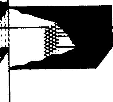
126 u I


127 (, g o 0 0+ \- a -s SL 129


128 a z 3 w 130


129 a,4 z x i i : ṁ Q ii - udq, c r! c G 131
130 HTGR PEBBLE BED REACTOR ~ Fig 32 Comparison of the main systematic dif - ferences of two typical designs with pebbles and prismatic fuel


131 n Q m o 0 d 4J v (-4 0 L9 L, > x - -+ m,! r: c1 E 133


132 0 0 l-( 134


133 I A 00!3 0 o 0, w of+ m, 135


134 w f- m \ 0 136


135 1= I i- UI G 0 w 0 z i 137


136 3 z 0 A u r- - V3 Ua


137 A 0 m \, m u w! 139


138 c o o o o o, 0 4 o P4 1! \ Oco H s n n U4 0

")


139 , l-l *!-l I I I I n n n n u-l u) l-l &9 no 141


140 o z 4 z ; 0 4 z 0 id c)


141 143 u


142 m q w 1- \ x 2 a a u w 144


143 4 9 1= (a a t \ \ ( * \ \- \ L 1 (2 z i 145


144 a i m / / w #m z 146


145 a Lu / / /, u z d a 147


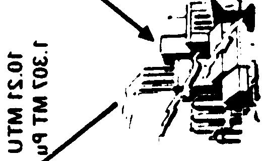


146 \ I \ - \ 4 IA a d C3 z i Ii a 148

147 149
148 TABLE 14 FUEL CYCLE REQUIREMENTS (1000 MWe, 75% LOAD FACTOR) REACTOR CHARACTERIZATIONS LMFBR1-AI Reference oxide Initial Equilibrium Load Cycle Mining (10 3 MT) Material Removed Uranium 02% concentration Thorium 02% concentration Milling (MT U ) MT =Enrichment Feed) Conversion (- (MT UF 6 ) Enrichment SWU (MT) Tails (MTU at 02%) Enriched product (MTU) Assay (% U-235) Feed nat U (MTM) Fuel Fabrication Input (MT) Output (MT) No Assemblies/year Composition Input U (MTM) From Enrichment tails Weight of Assembly (MTM) Used in Reactor Reactor load in Quantity (MTM) U\Pu\Th Isotopes (%) u-233 u-234 u-235 u-236 u-238 Pu-239 Pu-240 Pu-241 Pu deplu (03%U235) radial,bl 433/43/ , deplu (03% U-235) radial bl 1625/1528/0 o
149 TABLE 45 (Cont) FUEL CYCLE REQUIREMENTS (1000 MWe, 75% LOAD FACTOR) REACTOR CHARACTERIZATIONS Mixed Oxide Fuel Fabrication Input (MT) U\Pu output (MT) No Assemblies/year Composition Weight of Assembly (MTM) Used in Reactor Waste Disposal High Level Wastes (HLW+Cladding hulls) Volume (ft3) Activity (106 Curies) Activity of Pu (103 Curies) Canisters (a 35 ft 3 ) Low Level Wastes volume (ft 3 ) 55 Gallon Drums Burial or Repository Space (ft 3 ) Initial Load LMFBR1-AI reference oxide Equilibrium Cycle 2828/ / deplu0 2 +PuO 2 deplu0 2 +Puc core & axial bl core & axial bl ,000-42,000 2,240-5,880 3,200-8,
150 TABLE 14(cont) FUEL CYCLE REQUIREMENTS (1000 MWe, 75% LOAD FACTOR) REACTOR CHARACTERIZATIONS Reactor Discharge Quantity (MTM) U/Pu/Th Isotopics U-233 u-234 U-235 U-236 U-238 Pu-239 Pu-240 Pu-241 Pu-242 Th Fission Products (MTM) Net Plant Thermal Efficiency (%) Burnup in core (Avg MWd/MTM) Spent Fuel Storage Decay Heat (W/kg) Days Holdup Activity at Discharge From Pool (106 Curies FP) Fuel Reprocessing Input (MT) Recycle Uranium (MT) U-233 U-235 U-239 Plutonium Production (MT) Pu-239 Pu-241 Initial Load ,000 LMFBR1-A1 reference oxide Equilibrium Cycle 15135/l815/o o ,


151 ,!-l i! h (3 a 3 153


152 / f - Lil 0 \ 154


153 1-5 x u a 0 x 155

154 w


155 n 157


156 158
157 Table 16 MSBR (1000 MWe 75% Capacity Factor) Mining (103 MT) Uranium 02% concentration Thorium 02% concentration Conversion (=Enrichment Feed) (MT UF6) Enrichment SWU (MT) Tails (MTU at 02%) Enriched Product (MTU) Assay Feed nat U (MTM) Reactor Load in Quantity (U/Pu/Th) (MTM) Isotopics % u-233 U-234 U-235 u-236 U-238 Reactor Inventory Quantity (U/Pu/Th) (MTM) Isotopics % U-233 U-234 U-235 U-236 U-238 Net Plant Efficiency (%) Reload in kg/yr Th-232 Graphite Reload out kg/yr U-235 U-233 Start Up % / - / Equilibrium /-/

158 Natural Uranium Required (kg) Fig 43 Annual Natural Uranium Requirements to Enrichment Plant to Provide for 10 Mwt Reactor Annual Fuel Requirements 160

159 161
160 162
 % UJ")

161 FUEL ENRICHMENT ( % 235 U ) % UJ El / LJ a o r+ r- -i I I 1 / 1 163

 ANNUAL")


162 NATURAL URANIUM FUEL ASSEMBLIES 1255 Kg NATURAL URANIUM (1246 Kg U, 9 Kg U) URANIUM MINING & MILLING CONVERSION [10% LOSS) ANNUAL THROUGHPUT REQUIREMENTS FOR A 10 MWT BULK GRAPHITE OR HEAVY WATER MODERATED AND COOLED TANK TYPE, NATURAL URANIUM METAL FUELED RESEARCH REACTOR NATURAL URANIUM METAL 1255 Kg b 7 I II * MIXED OXIDE FUEL FABRICATION FOR REACTOR I


163 z - Ll - 1! \ \ 165
164 4 DIVERSION POTENTIAL OF REACTOR FUEL CYCLE MATERIAL** The proper perspective on nuclear weapon proliferation re - quires knowledge about nuclear weapon material requirements and their relation to reactor fuel cycle material Since a detailed analysis of nuclear fission weapon parameters would require a classified report, the unclassified details reported below only define the order of magnitude of the weapon requirements In any case, the exact amount, type, and geometrical configuration of material depends upon a specific design for a desired explosive yield The isotopes of particular interest for the construction of nuclear explosives are 233 U, 235 U, and 239 Pu (However, it should be noted that all Pu isotopes are fissile to fast neutrons) Since each of these isotopes have different nuclear properties, differing amounts of these materials, in pure form, are required to sustain a critical reaction Inside an infinitely thick, heavy metal-reflector, approximately 5 kilograms of 239 Pu or 233U, or 15 kilograms of 235 U are required for a critical mass (1,2) None of the nuclear power reactor fuel cycles can be considered ideal sources for weapons material since they do not contain isotonically pure, metallic* fissile material at any 1 H C Paxton, Los Alamos Critical-Mass Data, Los Alamos Scientific Laboratory report LAMS-3067, April W R Stratton, Criticality Data and Factors Affecting Criticality of Single Homogeneous Units, Los Alamos Scientific Laboratory, July 1964 * HTGR fuel comes relatively close, in that highly enriched uranium (93% 235U) is utilized * * See Appendix A for discussion of diversion potential from critical fuel cycle facilities 166
165 point in the fuel cycle The fuel cycles do, however, contain fissile material in other chemical forms such as oxides, carbides, or nitrates, typically mixed with other isotopes from the same element The other isotopes ( 238 U > 240Pu, 242 Pu) generally found in fuel cycle material act as impurities as far as weapons are concerned The inclusion of these isotopes does not preclude the use of the material for the con- 235 struction of weapons Material enriched with 20% or more U and any isotopic form of plutonium found in a power reactor fuel cycle could be converted to an explosive without enriching the isotopic fissile content of the material The larger the percentage of these isotopes, however, the less attractive the material becomes in terms of weapon parameters, such as explosive yield per gram, weapon size, spontaneous radiation from the nuclear material, and predictability The stable chemical forms of fissile material found in fuel cycles include the oxides, carbides and nitrate solutions Theoretically, pure oxide and carbide fissile material could be used (3) directly in a weapon core As before, the oxygen and carbon act as foreign elements by changing the fissile material density and scattering properties of the material The nitrate solutions could not be used directly in a weapon All of these chemical forms can be converted to metallic form, however, through standard chemical techniques found in open technical literature On the national threat scale, the chemical form of the fissile material presents no particular difficulty This may or may not be true for a terrorist or subnational threat 3 Mason Willrich and Theodore B Taylor, Nuclear Theft: Risks and Safeguards, Ballinger Publishing Co,
166 41 EXPOSURE OF STRATEGIC SPECIAL NUCLEAR MATERIAL An educational, but imprecise, technique for qualitatively classifying reactor fuel cycles is to look at the fuel cycle components for the various reactors having strategic special nuclear material (SSNM) exposed at some point in the process (Exposed is defined to mean that the material exists in a pure chemical form separated from other compounds and SSNM indicates that no further isotopic enrichment is necessary to produce weapons grade material) This taxonomic procedure is useful but does not necessarily rate the fuel cycles in terms of proliferation potential A systematic consideration of the threat, plus specific scenarios on the fuel cycle components, require additional information for a fuel cycle proliferation rating For example, in a country which contains only a reactor and no other fuel cycle components, the proliferation potential of-each of the fuel cycles is nearly the same The only proliferation difference exists in the difficulty of separating fresh fuel SSNM versus the separation of SSNM in irradiated fuel In Table 18 the exposure of SSNM for the representative reactor fuel cycles i S shown for the various fuel cycle components A quick perusal of Table 18 indicates that no ideal reactor fuel cycle exists -- they all contain SSNM 1n addition, SSNM is generally exposed in the facilities in the back end of the fuel cycle (ie, reprocessing and recycle fuel fabrication) Before discussing additional details relative to the exposure matrix table, the typical exposure modes for fuel cycle processes should be mentioned In an enrichment plant, the SSNM may appear as the output of the plant -- it is the end 168


167 I Ill 169
168 product of the process uranium hexafluoride or The chemical form of the SSNM is after conversion, uranium oxide (U0 2 ) This material is input to the fuel fabrication facility, where it is processed into fuel elements which are, in turn, input to the reactor After sufficient reactor operation, the irradiated fuel may be reprocessed; here the SSNM is exposed as the reprocessing plant product The typical chemical form for the reprocessing plant product is a nitrate or after conversion, an oxide This material may be then input to a recycle fuel fabrication plant and refabricated into reactor fuel and fed back to the reactor The light water reactor fuel cycle without recycle does not expose SSNM in its normal operation This is the present mode of operation in the United States, with the irradiated fuel temporarily stored until a reprocessing or permanent disposal decision is made The irradiated fuel contains significant amounts of plutonium In the LWR fuel cycle with recycle, SSNM (plutonium) is exposed at the reprocessing and recycle fuel fabrication facilities The rationale for recycle is more efficient utilization of the energy content in uranium fuel The economic basis for recycle is unclear, since total recycle costs have not evolved into a predictable value Uranium resources would be extended by recycle by about 30% It must be noted however, that there are alternative methods of extending the uranium resources to about the same fractional increase The use of more efficient converter reactors, such as the HTGR, the development of a high burnup, throwaway LWR fuel cycle, thorium fuel cycles, the tandem fuel cycle, or the development of laser enrichment (with a decreased tails enrichment) would all tend to extend the uranium resources The economic value and practicality of these alternatives has yet to be proven 170
169 An alternative reprocessing scheme is also available and technically proven In this scheme the uranium and plutonium are never separated but are decontaminated from the reactor poisons (fission products) only Some advantages of this scheme include the following: A simplified reprocessing flow chart, with fewer safety problems and improved efficiency Improved recycle fuel because of the intrinsic homogeneity of the coprecipitated uranium and plutonium oxides Improved safeguards because the uranium and plutonium would only contain approximately 15% fissile material A diverter would have to divert approximately 1000 kg of coprecipitated material to separate out 5 kg of fissile plutonium for a nuclear weapon The safeguard advantages are primarily against a subnational threat, since a national entity with large resources could, with relative ease, separate the plutonium from the uranium The major disadvantage of the coprecipitation reprocessing scheme is the recycle fabrication plant Large amounts of mixed oxide fuel have to be handled (increasing plant size), and all waste and scrap streams are contaminated with plutonium In addition, the mixed uranium-plutonium oxide has to be enriched to roughly 4% fissile content These disadvantages incur economic penalties which tend to detract from the advantages Heavy water reactors, like the Canadian CANDU, have a rather simple fuel cycle, with no reprocessing and no exposure of SSNM Even though the SSNM is not exposed during the standard CANDU fuel cycle, this reactor does have proliferation liabilities Because of the on-line refueling capabilities of the pressurized tube design, fuel management can be optimized to produce weapons grade plutonium with no power production penalty Of course, the fuel throughput must be increased accordingly; this, however, is a relatively minor economic penalty 171
170 There are heavy water reactors which utilize a pressure vessel design and consequential, off-line refueling A notable example of this is the German built reactor in Atucha, Argentina The high-temperature gas-cooled (HTGR) reactor promoted by the General Atomic Company in the US is the only operational civilian power reactor concept that utilizes fully 235 enriched uranium (93% U) as fuel The exposure of SSNM in the front end of the HTGR fuel cycle requires careful safeguards considerations, particularly if this concept becomes popular on a world-wide scale The manufactured HTGR fuel does have some intrinsic protection against a subnational threat, trivial task since recovery of the uranium is not a The backend of the HTGR fuel cycle has not been fully developed, not even to the i ncomplete extent of the LWR fuel cycle Consequently, a substantial uncertainty exists as to the relative economic merit of various HTGR reprocessing and recycling programs A recent report (6) indicates that the 235 most economic schemes involve mixing recovered U and 233 U for one recycle back through the reactor After the one recycle, the remaining 235 U and 233 U is retired The indications are that the HTGR recycle has a significant economic advantage over a throw-away fuel cycle HTGR recycle may be limited to a one-time recycle because of the build-up of 236 U -- a reactor poison 6 N D Holder, V H Pierce, and M P Rothstein, An Economic Analysis of U-235 Recycle in the HTGR, General Atomic report GA-A13836, July 15, 1976
171 HTGR recycle material has built-in protection against a 232 subnational diversion, because of the in-breeding of U -- an active precusor of a highly radioactive chain of daughter products For example, 5 kg of 233 U, containing 1000 parts per million of 232 U, would have a radiation dose rate near 10 Rem per hour, one foot from the material, after a 20 day delay period following uranium separation For longer delays, the radiation dose builds up to saturation level roughly 10 years after separation There are alternative HTGR fuel cycle concepts to the present fully enriched uranium-thorium fuel cycle A 1968 /7\ General Atomic report{ concluded that a low-enriched uranium fuel cycle, possibly as low as 6% 235 U, would have fuel cycle costs comparable to a throw-away thorium cycle A more recent economic analysis tends to support this conclusion The effect of utilizing a low-enriched fuel cycle would lower the conversion ratio substantially (it would now be roughly the same as LWRS), require more uranium fuel and introduce substantial quantities of plutonium into the fuel cycle It would, however, remove the exposure of SSNM from the front end of the HTGR fuel cycle The liquid metal-cooled fast breeder reactor (LMFBR) has SSNM exposed throughout its fuel cycle The enrichment facility is only needed in the fuel cycle, if the initial core load is made of enriched uranium and not plutonium Since the LMFBR is a breeder reactor (it produces it consumes) the reprocessing and more fissile material than recycle fuel fabrication plants are required components of the fuel cycle An important feature of an LMFBR is the amount of plutonium involved in the fuel cycle An initial load in a 1000 MWe reactor would involve some 3 to 4 metric tons of plutonium Annual reload requirements are roughly 1 ton of plutonium 7* P U Fischer, S Jaye, and H B Stewart, "Alternate Fuel Cycles for the HTGR," Gulf General Atomic report GA-9010, October 4,
172 The light water breeder reactor (LWBR) necessarily exposes SSNM in the backend of its fuel cycle Since it operates on a thorium fuel cycle, the comments on the inbreeding of 232 U in the HTGR fuel are also relevant here An interesting feature of the LWBR is that it is just barely selfsustaining Removal of significant quantities of SSNM from the fuel cycle shut down the reactor for power production or require a corresponding importation of fresh fuel The molten salt breeder reactor (MSBR), with its unusual fuel cycle, does not expose SSNM during its operational cycle, except for the possible production of roughly 3% excess fuel per year The initial core would most likely start up with 93% enriched uranium Research reactors are normally characterized by their small core fissile inventory, an uncertain operational schedule and lack of a commercial backend of the fuel cycle These features are generally considered positive assets for safeguards purposes On the other hand, research reactors are often sold on the basis of their flexible fuel management options and relative ease of refueling This flexibility gives the operators many options MTR (Material Test Reactor) type fuel is often used to generically describe uranium-aluminum alloy fuel clad in aluminum Fuel enrichments for research reactors using MTR type fuel vary from slightly enriched to fully enriched (93% 235U), with typical enrichments at 20% and 93% The MTP--type fuel plate is relatively easily processed to separate out the uranium The chemistry involved is well known and available in open literature TRIGA fuel elements consist of uranium-zirconium alloy The enrichment may be 20%, 70% or 93% The reprocessing and recovery of uranium from these types of elements is much more difficult than for MTR fuel 174
173 Heavy water moderated and cooled research reactors using natural or slightly enriched uranium fuel, appear to be the most easily safeguarded reactor They are, however, capable of producing plutonium on a small scale, as India proved in May DIVERSION PATHWAYS FOR SSNM Assuming that a political/technical decision has been made to develop the most effective nuclear weapons possible by diverting material from a reactor fuel cycle, the most cost effective, least detectable and lowest impact pathway to acquiring the necessary SSNM must be determined There is no simple, unique manner to make this determination It depends upon the threat (large country, small country, sub-national group), the resources available, and the specific reactor fuel cycle under attack In this section, we shall examine a few representative fuel cycles to illustrate the impact on the fuel cycle (power production, fuel throughputs, etc) and the additional facilities required to produce nuclear weapons from fuel cycle material Since fuel cycle plutonium is not optimum SSNM for nuclear weapons production, we shall also discuss fuel cycle tampering to produce fore favorable isotopic concentrations of SSNM At the bottom of Figure 49, the fuel cycle for a 1000 MWe CANDU-type heavy water reactor is depicted with annual equilibrium cycle fuel flows The most obvious, straightforward method for achieving nuclear weapons capability without affecting the power production is to reprocess spent fuel containing approximately 04 tons of plutonium (72% fissile Pu) into roughly 57 nuclear weapons This assumes a 1% Pu loss to reprocessing and SSNM rework and fabrication Each of the weapons would 240 contain 5 Kg of fissile Pu and nearly 2 Kg of PU PU 175


174 II L ( ( : I I I I II I 1 I I I I I I I I I I I I I I I I I I I I I I I I I I 176
175 Plutonium with a higher percentage of 239 Pu could, in principle, be achieved in a CANDU fuel cycle without causing any power production losses Instead of burning the fuel to 7500 MWd/MT, the fuel times faster, producing more total plutonium (58 MT Pu), with a more favorable fissile content (90%) This procedure would ultimately produce roughly 102 weapons per year for a 1000 megawatt reactor The only tampering indication would be the increased fuel throughput The key safeguards management point in the fuel cycle is the spent fuel An account of all the spent fuel emanating from the reactor counters this method of clandestine weapons production A surveillance technique for fuel removal from a CANDU reactor has, in fact, been demonstrated* The on-line refueling machine, of course, complicates the accounting of fuel bundles discharged from the reactor; however, the transfer channel can be monitored (for high activity gamma ray sources) to count the number of irradiation fuel bundles as they pass by on their way to the storage bay The item count of the stored bundles in the bay correlated with the tamper proof continuous surveillance monitor could -_ assure an inspector that all irradiated CANDU fuel is accounted for Monitoring of the spent fuel discharged from CANDU reactors is not presently required In Figure 50 a simplified 1000 MWe LWR fuel cycle with no recycle is depicted This fuel cycle is representative of the majority of power reactors operating in the world today Assuming 75% power production (ie, 75% capacity factor) for the year, this equilibrium cycle pressurized water reactor produces approximately 230 Kg of plutonium each year After * DB Siden, JG Hodgkinson, JW Cornbell, HD Kosanke, Testing of Techniques for the Surveillance of Spent Fuel flow and Reactor Power at Pickering Generating Station, International Atomic Energy Synposium on Safeguarding Nuclear Materials, October 1975, Vienna, IAEA-SM-201/67


176 LI I I I I I I I I I I a 178
177 accounting for losses, this amount 31 nuclear weapons of Pu could produce up to The isotopic concentration of the plutonium could be made more attractive for weapons (ie, from 69% fissile Pu to 90% fissile Pu) by lowering the fuel burnup from 33,000 MWd/MT to 8100 MWd/MT This, in effect, increases the fuel throughput in the fuel cycle For LWRs, however, the refueling must be performed off-line Consequently, a power production penalty must be paid for the additional refueling required by a lower burnup, higher fuel throughput For the situation depicted in Figure 50 the power loss is almost 1/3 the yearly power production, assuming that four refueling with typical down times (8) are required An additional indicator that an abnormal fuel cycle is in operation is the roughly 3 fold increase in fuel If this material is being imported (ie, the country has no enrichment capability), then the abnormal situation is discernible The lower burnup fuel can produce more plutonium than the normal fuel cycle (even with less power production), with higher Pu isotopic concentration The resultant weapons production increase is almost 50% There are, of course, other LWR fuel management schemes available to a reactor operator which produce weapons grade plutonium The impact on power production, fuel requirements, and weapons production may differ in detail from those depicted above The sense of the impacts is apparent, however The critical safeguards management point for LWR plutonium production is accounting for the spent fuel emanating from the reactor (as in the case for the HWRs) 8 A Fattah, R Skjoeldbrand, "Performance Analyses on Nuclear Power Plants from Operating Experience Data", IAEA-SM-195/36, Symposium on Reliability of Nuclear Power Plants, April 14-18,
178 LWR fuel assemblies have identifiable serial numbers that can be utilized by safeguards inspectors for accounting purposes However, BWR assemblies can and occasionally are disassembled to remove fuel rods This practice, potentially, could be subverted to produce optimum weapons material if a clandestine source of fuel rods is available A detection counter to this hypothetical threat is the use of tamper proof seals on BWR and PWR fuel assemblies These seals are presently under test and development* There is another credible weapons production possibility associated with the LWR fuel cycle The diversion of a portion of the slightly enriched fuel to a clandestine centrifuge enrichment plant could facilitate the production of nuclear weapons Assuming that a power production loss of roughly 1/3 is acceptable (to an overall capacity factor of 47%), thenalmost 10 tons of the 33% enriched uranium could be diverted to the centrifuge plant With a 07% tails enrichment, some 16 MT of separative work units (SWU) are required to produce 273 Kg of 93% enriched uranium This corresponds to roughly 16 nuclear weapons The number of centrifuges, at 5 Kg SWU/year capacity, required to further enrich the LWR fuel is over 3,000, These same centrifuges could be utilized to enrich natural uranium to weapons material at 93% enrichment This type of clandestine operation could produce approximately five uranium weapons, diversion method less than 1/3 the number produced by the fuel cycle * SJ Crutzen, R Haas, PS Jehenson, A Lamourox, "Application of Tamper-Resistant Identification and Sealing Techniques for Safeguards, International Atomic Energy Agency symposium on Safeguarding Nuclear Materials, October 1975, Vienna, IAEA
179 43 CONVERSION OF FUEL CYCLE MATERIAL TO WEAPONS MATERIAL A country desiring an efficient, reliable nuclear weapons capability, particularly one that would be handled by sophisticated delivery systems, would have to convert the fuel cycle material into weapons material This section summarizes the resources and physical facilities required to convert either plutonium nitrate or plutonium oxide to plutonium metal The conversion of highly enriched uranium to weapons material is somewhat similar, except that less attention would have to be paid to the containment of the uranium within the process The emphasis is on well-known and proven production processes as opposed to R&D or laboratory scale operations Other processes do exist and may be more efficient The required techniques and equipment are more complex, however Assumptions The simplest operational facility will be scoped No seismic or tornado design requirements will be imposed on the design Minimum contamination containment systems will be provided (ie only one level of filtration of process cell air will be considered) No scrap recycle or recovery will be provided scrap material will be treated as waste All All solid waste will be disposed of by shallow land burial All liquid waste streams will be disposed of by cribbing (shallow land disposal) All remote operations will be done in glove boxes Recovery rates as low as 85% of the original material as metal are acceptable All unit processes are batch type The two most important criticality control Parameters will be batch size and equipment design - There are two separate process steps to be considered The first is the conversion of plutonium nitrate to plutonium oxide; the second is the conversion of plutonium oxide to plutonium metal It is possible to go directly from the oxide to the metal or to by-pass the oxide on the way to the metal, but these processes will not be considered because of the assumptions stated above 181
180 There are two well-known, dependable processes for the conversion of plutonium nitrate to plutonium oxide These processes are referred to as plutonium peroxide precipitation and plutonium oxalate precipitation The flowsheet concepts are the same for both cases The plutonium feed streams are first adjusted for plutonium and acid concentrations Next, the precipitation agent, either oxalic acid or hydrogen peroxide, is added This is followed by a digestion period, then filtration of the plutonium precipitate The plutonium cake is then decomposed to plutonium dioxide by calcining the cake Figure 51 outlines a typical plutonium oxalate precipitation flowsheet The conversion of the oxide to the metal is a two step process The plutonium oxide is first converted to plutonium tetrafluoride by reacting the oxide with dry hydrogen fluoride Secondly, the tetrafluoride is reduced to metal by the high temperature, high pressure reaction with metallic calcium plutonium metal can be prepared in the massive state by reducing any of the several plutonium halides with an appropriate alkali or alkaline earth metal In practice, plutonium fluoride is used, principally because it is nonhygroscopic Figure 51 shows a typical material balance for reduction of plutonium fluoride Operational Cycle All unit operations are assumed to be batch type separations This allows the design of the equipment to be simple and manually operated Criticality control is also important in the design Based on a batch operation with approximately 5 Kg of plutonium being processed, the following operational time cycles might be expected: 1 Feed adjustment, precipitation, and digestion 15 hours 2 Filtration 075 hours 3 Drying, calcination, and hydrofluorination 45 hours 4 Reduction 50 hours 1175 hours 182
2 O2M H + 30M NO; 28 M C 2 o:- 01 M DIG TIME 1 HR DIG TEMP 55 c 21 VOLUMES WASH HN0 3 2M H 2 C204 005M 5 VOLUMES FILTER CAKE PU(C 2 0 4 ) 2 6H 2 O Pu 99% HN0 3 08M H 2 O 20M 2 VOLUMES Fig 51")
181 FEED # OFF GAS P u o IOOG/LITER(lOO%) H + 5M I N O 58M 10 VOLUMES O* 150 VOLUMES (S I P) STRIKE SOLUTION 50% H VOLUMES 1 MH 2 C VOLUMES 1 PRECIPITATION SLURRY p u G/LITER Pu(c )2 O2M H + 30M NO; 28 M C 2 o:- 01 M DIG TIME 1 HR DIG TEMP 55 c 21 VOLUMES WASH HN0 3 2M H 2 C M 5 VOLUMES FILTER CAKE PU(C ) 2 6H 2 O Pu 99% HN0 3 08M H 2 O 20M 2 VOLUMES Fig 51 Plutonium Oxalate Precipitation Flowsheet 183


182 t POWDER CHARGE P uf G Pu 500 G I f A REDUCING AGENT CALCIUM 225 G 25% MOLAR EXCESS m BOOSTER IODINE 80 G 015 MOLE 1 2 / MOLE FUEL L CERAMIC CRUCIBLE Mg O 500 G 4 v MIXER I Mg O SAND FILL ANNULUS BETWEEN CRUCIBLE & PRESSURE VESSEL Mgo 470 G m VACUUM SOURCE I VESSEL PURGE I HIGH PRESSURE PRODUCTION VESSEL INERT GAS VESSEL PURGE ARGON 1 LITER I HEAT SOURCE I EG INDUCTION FURNACE 500 Psl 1600 C t - I J I BUTTON I FRAGMENTS MgO 970G CaF2 326G Ca Ca 45G Pu IOG BUTTON I 7 / Pu 4899 G Fig 52 Plutonium Fluoride Reduction Material Balance 184
183 The total cycle time for a one 5 Kg batch of plutonium metal is approximately 12 hours But it is important to note that there are two independent operations which require a majority of the process time These are the hydrofluorination step and the reduction step This means that both operations could be conducted at the same time, allowing a 5 Kg batch of plutonium to be produced every six hours This means a total of 20 Kg of plutonium metal per day, with a single process line using all of the equipment designed to handle 5 Kg batches of plutonium The selection of 5 Kg batch sizes is considerations, in that it is reasonably critically safe equipment for 5 Kg batch sizes present more of a problem based on criticality easy to design sizes Larger batch For a single process line, it is conservatively estimated that all of the process and support areas could be contained within a 3,600 ft 2 building The actual glove box process area would be no larger than 350 ft 2 with operational glove ports in the front and maintenance access through the back Cost Estimates The following order-of-magnitude process line operation estimate is for a Process Equipment Building Piping and Instruments Glovebox system Building Ventilations Personnel Support Systems $ 750, , ,000 75,000 45,000 50,000 TOTAL $ 1,420,
184 These costs include all direct and indirect costs, such as design, engineering, construction and startup The numbers are only representative of the simplest operating facilities There are three important time increments in any construction schedule These time periods are: Scoping and design Procurement Construction The controlling scheduling factor for the construction of a facility such as the one being discussed is procurement The reason for this is that several major items of equipment must be fabricated to specific design and require somewhat unusual materials The three longest lead items for procurement are the hydrofluorination vessel, the hydrofluorination furnace, and the reduction furnace Following the detailed designs of these items, procurement would probably require 14 to 24 months fabrication It is important to note that detail design and construction of the building and operational support systems can be underway during the procurement phase With good coordination between all phases of the project, operational startup could be between 24 to 36 months after the start of the project 1/36
185 5 SUMMARY OF REACTOR CHARACTERISTICS There are many characteristics pertinent to power reactors that are decisively important to countries that wish to purchase a reactor The previous sections discussed in detail the general technical and quantitative aspects of the power reactor fuel cycles This section will summarize some of these technical detail-s concentrating on the resource utilization and safeguards characteristics Many of the other characteristics are often subjective by nature or specific to a particular situation and not amenable to a generalized technical discussion A partial list of reactor characteristics that sidered by a country embarking upon a nuclear power include the following: 1 Remaining R&D problems and requirements 2 Resource requirements 3 costs 4 Fuel cycle independence 5 Design available in size desired 6 Environmental effects 7 Safeguard characteristics might be conprogram should Remaining R&D problems and requirements are listed first on the list, not necessarily because it is the number one consideration, but because it focuses attention on the power reactor fuel cycles that would be considered by a country that wishes to purchase a reactor At the present time only the light water reactors and the CANDUS are available in essentially off-the-shelf designs 187
186 The other reactor concepts require considerable R&D to achieve a commercial status We will limit the remaining discussion to the reactors that might be commercialized within the next decade: PWR, PWR with recycle, BWR, BWR with recycle, CANDU-PHW, HTGR, AGR and LMFBR (Over the next decade isotopic enrichment methods are likely to advance faster than the other reactor concepts -- consequently in 10 years, edge as a potential proliferation pathway) uranium enrichment may have the clear Table 19 summarizes the equilibrium fuel cycle material flow characteristics along with other pertinent characteristics The material utilization is normalized to 1000 MWe and a 75% capacity factor included in Table 19, however, The requirements for a BWR recycle reactor is it must be noted that there are many recycle fuel management plans that could be utilized, some of which differ significantly from that listed in Table 21 The net fissile material utilized to produce 1000 MWe is substantially less for a heavy water reactor like the CANDU than for other reactor types (approximately 33% less than for a PWR) This efficient use of fissile material is a direct manifestation of the superior neutron economy of heavy water reactors If the amount of fissile material remaining in the tails of the enrichment process is included this difference is even higher On the other hand, the amount of energy necessary to supply the heavy water is not included In addition, a more efficient utilization of fissile material could be achieved in the LWR s via the use of a tandem fuel cycle, recycle fuel cycle management plan, or an optimum throw-away fuel cycle There is little room for improvement in a heavy water fuel cycle without substantial reactor design changes
187 I i I I I I ṉ = - I C# I I c% -x 199
188 costs are certainly an important point in considering a reactor purchase However, the total capital cost often is determined by the financial arrangements, We note here that the total capital costs of LWRs are thought to be at least 10% less than for an equivalently sized CANDU Natural uranium reactors such as the CANDU offer fuel cycle independence to those countries not having enrichment facilities In addition, they are generally available in smaller sizes (600 MWe is to be a standard export CANDU whereas most present LWR designs are over 1000 MWe) The smaller size power station is often more compatible with a country s electric power grid (Because of the necessary shutdowns for refueling and maintenance, no single power station should be more than approximately 15% of the total grid capacity) The environmental effects of the various reactors do differ The lower efficiency reactors such as the CANDU promote more thermal pollution Some reactors produce more of certain types of radioactive isotopes However, none of these considerations are decisive in a proliferation potential discussion In Table 20 some of the reactor safeguards considerations relative to various threats are summarized If a country manufactures fuel rods from raw materials then the LWR with recycle, the HTGR, and the LMFBR could be credibly threatened by any of the groups listed If a country receives only fresh fuel assemblies then the threat diminishes somewhat for these fuel cycles All of the irradiated fuel from the various reactors contain strategic special nuclear material A credible threat can be directed against this material if the group can put together the necessary facility to separate this SSNM from the highly radioactive fission products 190
189 Table 20 REACTOR SAFEGUARDS CONSIDERATIONS Reactor Fuel Material MATERIAL EXPOSURE LWR LWR with CANDU- Recycle PHW HTGR AGR LMFBR Fuel (Raw Materials) o Fuel Assemblies o Irradiated Fuel e 1 1 $ No Strategic Special Nuclear Material (SSNM) involved SSNM involved but must be separated in reprocessing plant SSNM can be separated by standard chemical and mechanical processes (no high radiation) SSNM could be converted with little or no processing into a weapon MATERIAL EXPOSURE RATING VERSUS THREAT Subnational Group Nation Desiring a Quick Response Capability Small Nation Large Nation I Rating o 1 ) 3 Credible Threat I r REACTORS VERSUS THREAT CREDIBILITY LWR LWR with CANDU- Recycle PHW HTGR AGR LMFBR Subnational Group c c c Nation Desiring a Quick Response Capability c c c Small Nation u c c c u c Large Nation c c c c c c C- credible threat 17 - credible but unlikelv 191
190 It seems obvious that exposure of SSNM in the power reactor fuel cycle either through the use of reprocessing and/or SSNM in fresh fuel assemblies makes the fuel cycle somewhat more vulnerable to a broader spectrum of threats The decision as to the relative significance of this increased vulnerability might better be answered by other considerations such as: 1 Can effective safeguard measures be incorporated to counter this increased vulnerability? 2 How significant is this vulnerability relative to the use of dedicated facilities? Extensive programs are being conducted in the United States by ERDA and NRC, and throughout the rest of the world to arrive at acceptable answers to these questions 192
191 BIBLIOGRAPHY WASH-1099, Reactor Fuel Cycle Costs for Nuclear Power Evaluation, USAEC, December 1971 Directory of Nuclear Reactors, IAEA, Vienna, 1976 Vol X, Power and Research Reactors, Comprehensive Standards: The Power Generation Case, EPA No , Teknekron Inc Report, March 1975 Kiat Peon Aug: Quantities of Actimides in Nuclear Reactor Fuel Cycles PhD Thesis, April 1975, LBL Berkeley WASH-1098, Potential Nuclear Power Growth Patterns, USAEC December 1970 WASH-1139 (74), Nuclear Power Growth , USAEC February 1974 Study of Advanced Fission Power Reactor Development for the United States, Final Report, I, II, III Battelle, Columbus Laboratories, June 1976 DEW Leaver: Strategies for Plutonium Recycle in a System of Pressurized Water Reactor, PhD Thesis Stanford University, Dept of Mech Engineering, Stanford, March 1976 WASH-1348, Computer Program NUFUEL for Forecasting Nuclear Fuel Requirements and Related Quantities, USAEC October 1974 WASH-1327, Generic Environmental Statement Mixed Oxide Fuel, USAEC, August 1974 Directory of Nuclear Reactors, Vol VII, Power Reactors IAEA, Vienna 1968 The World s Reactor No 20 November , SNUPPS, Nucl Eng International, Proposed Final Environmental Statement-LMFBR Program, USAEC Report No WASH-1535, Vol 1 to VI1, December 1974 WASH-1400 (NUREG-7S 1014) Safety Design Rationale for Nuclear Power Plants, Appendix IX, Fig IX-31-1; USNRC, October
192 R Harris, JM Christenson: Post Shutdown Fission Product Decay Heating for Plutonium 239 fueled Fast Reactors, Nuc1 Technology 25, 440 (1975) Directory of Nuclear Reactors, Vol IX, Power Reactors IAEA, Vienna 1971 RC Smith, LG Faust, LW Brackenbush, NUCl Technol 18, 97 (1973) E1-Wakil, MM, Nuclear Energy Conversion, International Text- Book, Scranton, Pa 1971 Development Status and Operational Features of the High Temperature Gas-Cooled Reactor, Electric Power Research Institute, April, 1976, EPRI NP-142 Rippon, Simon, The AGRs Make a Start, Nuclear Engineering International, April/May, 1976 "Hinkley Point B, A Survey of Design and Construction", Nuclear Engineering, Vol 13, No 147, August 1968 World List of Nuclear Power Plants, Nuclear NEws, Vol 19, No 10, August 1976 Hinkley Point B Power Station Directory of Nuclear Reactors, Vol X, International Atomic Energy Agency, March 1976 "Dungeness B Nuclear Power Station", Directory of Nuclear Reactors, Vol X, International Atomic Energy Agency, March 1976 Hunterson B Generating Station, Directory of Nuclear Reactors, Vol X, International Atomic Energy Agency, March 1976 Nuclear Power Growth , WASH-1139, USAEC February 1974 Snyder, AJ, Computer Program NUFUEL for Forecasting Nuclear Fuel Requirements and Related Quantities, WASH-1348, USAEC October 1974 Rippon, Simon, Reprocessing - What Went Wrong?" Nuclear Engineering International, February 1976 Oehme, H, Comparative HTGR Designs, in Gas Cooled Reactors: HTGR and GCFBR, ANS Topical Meeting, CONF , May 1974 Boyer, VS, et al, Fulton Station HTGR Nuclear Engineering International, Vol 19 No 2, 19 August 1974, pp
193 Walker, RE, and Johnston, TA, Fort Saint Vrain Nuclear Power Station, Nuclear Engineering International, December 1969 Brooks, LH, Lotts, AL, and Wymer, RG, Progress in the Thorium-Uranium 233 Reprocessing-Refabrication Technology, in CONF Heath, CA, and Spaeth, ME, Reprocessing Development for HTGR Fuels, in Proceedings of Joint Topical Meeting on Commercial Nuclear Fuel Technology Today, AND and CNA, April 1975 Study of Advanced Fission Power Reactor Development for the United States, Vol III, Battelle Columbus Laboratories, BCL-NSF-C9&6-2, June 1976, pp C-69 through C-76 THTR, Prototype-Kerkraftwerk Uentrop, in Directory of Nuclear Reactor Vol X, IAEA, March 1976, pp Pigford, TH, et al, Fuel Cycle for 1000 MWe High Temperature Gas-Cooled Reactor, Teknekron Report No EEED 105, March 1975 Pigford, TH, et al, Fuel Cycles for Electric Generation, Teknekron Report No EEED 101, January 1973, Pg 194 CANDU Nuclear Power Station, AECL, October 1973 CANDU 500 Pickering Generating Station, AECL, 1969 McIntyre, HC, Natural Uranium Heavy-Water Reactors, Scientific American Vol 223, No 4 October 1975 Masters, Richard, Co-operation and Concentration Pay Dividends in Canada, Nuclear Engineering international Vol 2, No 244, June 1976 Taylor, ML and Therrien, M Gentilly-Commissioning and Early Operation Nuclear Engineering International, Nov 1972 Pen, GA, Candu-BLW-250 in Heavy Water Power Reactors IAEA, Vienna, 1968 Duret, MG, Plutonium Production and Recycle in Heavy-Water Reactors, in Heavy Water Power Reactors, IAEA Vienna, 1968 An Evaluation of Heavy-Water Moderated Organic Cooled Reactors, USAEC, WASH-1083, March 1968 An Evaluation of a Heavy Water Moderated Boiling-Light Water- Cooled Reactor USAEC, WASH-1086, Dec 1969 Lane, JA, et al, Comparative Evaluation of the Performance and Economics of Heavy-Water-Moderated Reactors, in Heavy Water Power Reactors, IAEA, Vienna 1968 Barnes, RW, and Mayman, SA, The Canadian Program for Management of Spent Fuel and High Level Wastes, in Proceedings of Joint Topical Meeting on Commercial Nuclear Fuel Technology, ANS and CNA, April
194 APPENDIX A DIVERSION POTENTIAL OF CRITICAL FUEL CYCLE FACILITIES
195 Fuel cycle facilities that may contain strategic special nuclear material in a separated form are of particular interest to a safeguards and proliferation assessment The exposure matrix (Table 18 ) lists the critical facilities for the various power reactor fuel cycles Enrichment plants, reprocessing and possibly to a lesser extent recycle fuel fabrication plants merit special attention as explicitly implied in Table 20 The capability of an enrichment plant and reprocessing plant to generate separated strategic special nuclear material makes them particularly vulnerable to a diversion threat Reprocessing Plant There have been a number of reasons expressed by various countries for acquiring a reprocessing plant Included among these reasons are typically the following: 1) Going to light water recycle fuel to more economically operate LWRs, con-serve uranium resources, and to gain more control over their LWR fuel cycle 2) Eventually expect to go to a breeder fuel cycle which must include reprocessing The reprocessing plant is needed to gain the necessary experience 3) Spent LWR fuel assemblies have to be reprocessed to generate an acceptable waste disposal form All of these responses have a base of validity; however, the firmness of these bases is uncertain at the present time For example, the economic gain in using LWR recycle fuel is a rather sensitive function of uranium prices and the cost of reprocessing Neither of these costs are firm at the moment and they have a rather large uncertainty for a time period eight years in the future (following the decision to 196
196 build a plant) when a reprocessing plant might come on line The conservation of resources argument is certainly true with a most likely uranium savings of 25% However, as discussed in Section 41, there are alternative ways of achieving roughly the same gain in resources without resorting to the use of recycle LWR fuel The other arguments (2 and 3) also have rather large associated uncertainties which preclude them from being definitive statements on a perceived positive requirement for a reprocessing plant For example, it is clear that any breeder fuel cycle requires reprocessing However, it is not clear that breeder reprocessing will utilize the PUREX process that is standard for production metal fuels and the oxide fuels of LWRs Consequently, experience in reprocessing LWR fuel may only apply in a limited way toward the reprocessing of LMFBR fuel because of the higher burnup, higher plutonium throughput, and possible fuel dissolution problems with LMFBR fuel The West Germans have repeatedly stated that reprocessing of spent LWR fuel gives them a flexibility in developing waste disposal forms that will be acceptable for disposal in their country Until recently, US policy has assumed a base case fuel cycle that includes reprocessing and waste treatment prior to disposal The alternative of directly disposing spent fuel assemblies (after some treatment) has been assumed to be technically feasible There has not been an extensive experimental program to demonstrate this, however An additional argument against a country developing an indigenous reprocessing capability is that analysis indicates* that large plants are by far the most economical Large plants mean a capacity of 1500 to 3000 MT (roughly 15 to 30 MT of Pu) capacity per year, or fifty to one hundred 1000 MWe nuclear * Light Water Reactor Fuel Recycle, Savannah River Laboratory Quarterly Report, DPST-LWR , January-March,
197 power reactors Few countries outside the US are expected to develop a nuclear power reeactor electric generating capacity of this magnitude Moreover, there are design problems associated with large capacity reprocessing plants (particularly for those greater than 1500 MT capacity) that have not been completely resolved These problems are primarily related to ensuring that a sufficient criticality safety factor is achievable under all credible circumstances Reprocessing plants have one obvious proliferation potential when viewed in the context of a national threat If the host country abrogates the Non-Proliferation Treaty and refuses to allow IAEA inspection of the operating reprocessing plant, then the country can rather overtly proceed to generate weapon material from the stockpile of spent fuel (The likely amount of Pu that could be separated from spent power reactor fuel is listed in Appendix B1 for the various countries One result of an overt proliferation attempt might be the shutoff of the imported fresh LWR fuel from supplier countries An assessment of covert diversion of plutonium from a reprocessing plant by the host country or by a subnational group requires some consideration of the material form and flow through the reprocessing plant Figure Al* is a schematic illustration of the principal physical areas and average daily material flow through a model 1500 MT\year reprocessing plant The principal areas are: * G Bray and H Kendrick, Spent Fuel Reprocessing Plant Characteristics Important to an Integrated Safeguards Design INMM 17 Annual Meeting, Seattle, Washington January 22-24, 1976 PP


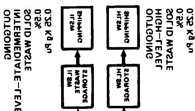


198 199
199 Spent fuel receiving and storage plutonium, uranium and fission product separation Plutonium nitrate blending and storage Plutonium nitrate-to-oxide conversion Plutonium oxide storage and shipping The average daily plutonium flow between plant areas is shown in the figure The daily plutonium flow is expressed in kg Pu/day and as a percentage of the average 50 kg Pu/day assumed coming into the plant Plutonium assay stations and accountability tanks, which are required for material balance accounting are also shown in Figure Al The data and physical arrangement shown is intended to be representative of present design criteria The cress-hatched enclosures of the spent fuel receiving and storage area and the separations area indicates the highly radioactive nature of these areas Material in these areas is not attractive for diversion The plant processes manifest certain key characteristics which relate to the attractiveness of the material to potential diverters, and to the accessibility of the material The attractiveness of the material can be expressed in terms of the form (chemical composition, physical form, packaging, etc), concentration (grams plutonium per gram of material), and the presence or absence of hazardous levels of radioactivity The accessibility of the material is related to its form, the type of processing or material-handling equipment used, the degree of automation of that equipment, and the quantity of plutonium available in a given location Key process characteristics have been determined for all areas of a model reprocessing plant, including both mainstream and sidestream material flows, and are shown in Figure A2 290


 x \")


200 Quantity Normally in Process Area I [ SPENT FUEL RECEIVING AND STORAGE SEPARATIONS [ Pu OXIDE SKIPPING Handling and Process Techniques Scrap and Waste Generation Time to Acquire 100 Rem Dose at 1 meter from 1 Kg x (TRACE) x \ SEPARATIONS x x x x x x x x x x s 1 II Pu NITRATE 8LENDING AND STORAGE Pu N[TRATE TO OXIDE conversion Pu OXIDE STORAGE c) 201
201 These figures illustrate the important differences in process characteristics across the plant The figures on the left side of Figure A2 represent the maximum quantity of plutonium that normally might be present in the various plant areas, the chemical form of this material, and the possible range of plutonium concentration in this chemical form Note that the high points on the figures represent the more attractive material from a diversion standpoint The three figures on the right side of Figure A2 are measures of the accessibility of the material in the various plant areas The top figure on the right illustrates the time necessary to acquire a 100 REM dose at a one-meter distance from one kilogram of material As before, the high points on the figure represent the more accessible material (ie, less radioactive) Scrap and waste (middle figure, right side of Figure A2) generally is considered to be more accessible material partly because it may indicate a process upset and often is more difficult to accurately measure Even though the scrap may not meet the customer s specifications, it may still consist of relatively concentrated Pu material that can be reclaimed and transformed to weapon material In addition, scrap and waste represent outgoing material streams from the main process line The lower righthand figure illustrates the handling and process technique The accessibility to the Pucontaining material is rated from manual through automatic Considering all of the characteristics of the various areas delineated in Figure A2, the Pu nitrate blending and storage area, the Pu nitrate to oxide conversion area, and the analytical laboratory all would appear to be critical areas for material measurements and accounting An indication of an accounting system detection capability for the conversion area of our model reprocessing plant that is operating with presently available measurement equipment and an accounting interval 202
202 period of two months (US NRC requirement) is that an individual or group has a 50 per cent chance of avoiding detection by the accounting system if they divert 132 kilograms of plutonium For the analytic laboratory, the SO per cent probability of detection amount is 1 kg of Pu for the two-month accounting period If these systems were upgraded to state-ofthe art measurement instrumentation, approximately 87 kg of Pu from the conversion area, or 05 kg from the analytical laboratory, or 117 kg Pu from the nitrate blending and storage area could be diverted with a 50 per cent probability of detection by an accounting system It is highly likely that these upgrade numbers represent the most optimistic detection capability since many of the assumed measurement capabilities are laboratory results that may degrade when introduced into a production facility The larger numbers quoted above are achievable with proven measurement hardware and procedures Accounting procedures monitor nuclear material in the main process stream, the associated sidestreams and, of course, the sealed, item count material in storage Undetected diversions from these areas are statistically possible for measurement and accounting systems as discussed above However, the material must then be removed from the process line or storage area Now a number of containment and surveillance procedures come into play that are designed to detect the removal of the nuclear material from its authorized location Many of these surveillance procedures can utilize tamperproof hardware that can be left unattended by IAEA inspectors A partial listing of these procedures include the following: portal monitors for nuclear material CCTV surveillance door or glove box access alarms motion detectors random personnel or package searches clothing changes randomly located radiation detectors 203
203 The applicability of specific procedures varies according to the particular area; however, it should be possible to design and implement a set of redundant protective measures to meet a specified subnational threat (for example, six adversaries with two being inside employees) to the material access areas Consequently, an undetected diversion of nuclear material would have to overcome the containment and surveillance systems in addition to the measurement and accounting systems The reprocessing diversion potential as described above differs if an alternative reprocessing scheme is employed For example, if a coreprocessing scheme (see Section 41) is used so that none or only some of the uranium is separated from the plutonium, then the model plant is changed along with measurement procedures Most significantly, the amount of material a divertor would have to remove to obtain a strategic amount of special nuclear material is increased In addition, the divertor would have to chemically separate the plutonium from the uranium For subnational groups, the required chemical separation could be a significant obstacle to overcome 204
204 ENRICHMENT PLANT An enrichment plant is the only other nuclear fuel cycle facility besides a reprocessing plant capable of generating separated strategic special nuclear material A significant difference exists, however, in that a reprocessing plant normally handles an intrinsic strategic special nuclear material --plutonium; whereas an enrichment plant built to service a LWR fuel cycle would only generate slightly enriched uranium (approximately 3% 235 U) Consequently, the diversion/proliferation potential of an enrichment plant exists in its potential capability for generating highly-enriched uranium (typically 90% or greater 235 U) Since most commercial enrichment plants will only be designed and operated to produce slightly enriched uranium, the proliferation threat to the facility is limited somewhat It is not credible that a small group of adversaries (particularly outsiders) could subvert the normal plant operation to produce hiqhly-enriched uranium A credible threat would have to include most of the plant management and many of the operating personnel the operating country facility Thus, is of a diversion threat directed by most concern for an enrichment The remainder of be primarily directed this section on enrichment plants will toward centrifuge enrichment plants There are two main reasons for focusing this discussion of the proliferation - potential of enrichment plants on centrifuge techniques and facilities rather than the present dominant enrichment technique of gaseous diffusion: 1) Centrifuge plants can be initially constructed with a modest separative work capacity and then added to as the demand for enrichment services grows Gaseous diffusion plants make economic sense only in very large capacity such as 9,000,000 kg SWU\year 205
205 2) Gaseous diffusion plants require approximately 15 times more electric power per SWU than centrifuge plants (The Becker nozzle process which requires somewhat fewer stages but consumes more than twice as much electric power as gaseous diffusion is also not an attractive choice for production of weapons material) These points are discussed in more detail in Section 25 and 211 The primary effect on the above is that small enrichment plants, particular those build with a limited amount of capital, will undoubtable be centrifuge plants The advanced isotope separation processes such as laser enrichment techniques are not likely to be available for use before 1985 Before concentrating on the centrifuge technique, it is of interest to note a few technical differences between gaseous diffusion and centrifuge enrichment that relate to their diversion potential Enrichment Limits The amount of enrichment obtainable from a single barrier in a gaseous diffusion plant (GDP) is small and relatively fixed Consequently, all barriers are connected in series, thus limiting the maximum enrichment that can be obtained with natural uranium feed The amount of enrichment from a single centrifuge is much larger and variable as discussed below Electric Power Usage The amount of separative work performed in a GDP is proportional to the power used to pump the UF6 through the plant Thus, the power usage is a direct and external indicator of the SWU actually performed The power used to drive the centrifuges is relatively small and a poor separative work indicator process Inventory The process inventory of a GDP is orders of magnitude larger than that of a centrifuge enrichment plant Since there is always a rather large uncertainty associated with the process inventory, this could create a rather large MUF in GDPs 206
206 To facilitate a coherent discussion of centrifuge enrichment plants, we shall develop a reference centrifuge plant following Kouts* The characteristic parameters listed are nominal values traceable to results reported in the literature; however, there may be significant differences between these reference values and those actually utilized in a specific centrifuge plant For example, European centrifuge development (Urenco) is known to be concentrating on developing highly reliable (failure rate less than 2 per cent per year), low-capacity centrifuges, whereas American development efforts are reported to be directed toward higher separative work capacity machines with a reduced reliability Hopefully, the reference characteristic numbers are somewhere in between these values Table A2 lists the design characteristics of the reference centrifuge enrichment plant Note that this is a very small plant (when compared with US diffusion plants), representative of the initial enrichment plants expected to come on-line in Europe and Japan A mature LWR industry would require much larger plants with at least an order of magnitude or more additional capacity Table A3 lists the design material flow through the individual cascades Table A4 illustrates the cascade that produces 4% enriched 235 U Note there are 29 stages with varying numbers of centrifuges in each stage The other cascades that produce a lower enrichment product are similar in nature with fewer stages * Herbert Kouts, "Reference Uranium Enrichment Plant," Technical Support Organization, Brookhaven National Laboratory, December 6,
207 TABLE A2 REFERENCE CENTRIFUGE PLANT Total Separative Capacity MT SWU/Yr Unit Separative CapacitY kg SWU/Yr Number of Cascades Number of Centrifuges Per Cascade Total Feed Rate MTU/Yr (natural uranium) Total Product MTU/yr (various enrichments) Total Tails 235 MTU/Yr at 25% U Centrifuge Floor Area ft 2 Centrifuge Building Area ft 2 Nuclear Power Industry Supported 1000 MW(e) , , ,000 about
208 TABLE A3 MATERIAL FLOWS IN THE CASCADES Product Enrichment (% U -235) Feed (Tonnes U/Y r ) Product (Tonnes U/Yr) Tails (Tonnes U/Yr) TOTAL
209 TABLE A CENTRIFUGE represent centrifuge per Enriching Stages I I
210 An important feature to note about the above example is that centrifuge enrichment plants are inherently versatile --much more so than gaseous diffusion plants This versatility that is inherent with the overall configuration of centrifuges in an enrichment plant also extends to the operation of individual centrifuges Figure A3 illustrates the characteristic curies of enrichment for a gaseous centrifuge The top figure shows the variation in separative work with feed rate and the bottom figure the variation in the enrichment factor with the feed rate The implication of these curves are that changes in the plant operation can produce an enriched product that is higher than the design enrichment Measurements and material accounting in enrichment plants that produce slightly enriched uranium can be viewed from a different prospective than for reprocessing plants because the normal product material does not contain strategic special nuclear material Nevertheless, material accounting can be important for some diversion scenarios and it is of interest to consider the various loss mechanisms as causes of inventory uncertainty A comprehensive list of uranium loss mechanisms would have to include: traps in vacuum system centrifuge failure centrifuge maintenance accidental losses wet air inleakage reaction of UF6 with impurities intermetallic diffusion surface absorption of UF6 active chemisorption of UF6 The importance and absolute gram value of each of these mechanisms is difficult to predict in the absence of experimental data from a production centrifuge plant The total loss might be comparable with that of a GDP which is 05 per cent of the product (for 4 per cent enrichment) 211
211 Relative Feed Rate = I 1 I 1:0 Figure A3 Assumed Centrifuge Characteristics 212
212 A quick consideration of material diverted within the material measurement and accounting uncertainly indicates that this amount of material is not very important for a plant the size of the reference plant Assume a physical inventory every three months The expected accuracy of material accounting (IAEA) should be 2 per cent of the throughput for this period This corresponds to roughly 1 kilogram of highly-enriched uranium every three months if all this could be diverted and enriched to 90% 235 U -Table A5 shows typical inventories inside the fenced area We note that the major inventories are in the feed, product, and tails These can be measured quite accurately 2% and thus contribute a rather small total uncertainty to the plant inventory To complete the reference plant model, a layout of the plant is shown in Figure A4 The cascade area (which at present is not accessible to IAEA inspection) also contains the sensitive areas associated with the plant such as the centrifuge maintenance, decontamination, and test areas as well as the control room In the US and possibly elsewhere an outside perimeter fence would surround the entire plant The key measurement points (KMP) for flow, inventory, and surveillance are as indicated on the figure As stated above the prime diversion potential associated with these types of enrichment plants is related to an undeclared upgrading of material beyond the maximum enrichment designed into the plant There are a number of ways that this could be accomplished: 1) Reconfiguration of unit cascades 2) Recycle of plant product 3) Off-design cascade operation 4) Internal cascade recycle 213
213 TABLE A5 TYPICAL IVENTORIES IN FENCED AREA Location Gas Phase in Centrifuges Traps Deposition in Centrifuges Feed* Product** Tails*** Waste Recovery kg u Nominal kg U O 95 * Assumes 1 half-full cylinder feeding all cascades from feed purification, 1 cylinder waiting ** Assumes equivalent of half-full cylinder at each product withdrawal point ***Assumes tails from separate cascades sequestered Equivalent of half-full cylinder at each tails withdrawal point 214


214 x H 215
215 The implications or details of discussed in turn each of these will be 1) 2) 3) 4) The centrifuges in one or several of the cascades could be reconfigured to take natural uranium feed to a 90 per cent enriched product A cascade that would accomplish this might consist of 77 enriching stages and 10 stripping stages Each stage could, of course, contain a minimum of one centrifuge Consequently, this covert cascade could conceivably be constructed from one of the 8000-unit reference cascades If the 4 per cent product were fed into another covert cascade that had a natural enrichment tails, then 58 enriching staqes would be required with 18 stripping stages Again, this cascade could be configured from one or a portion of one of the model cascades The feed rate, product rate, and reflux ratio (the relative amount of interstage circulation to product flow) could be varied to produce a more highly enriched product The maximum enrichment obtainable requires a detailed analysis; however, it is not likely to exceed 20% 235U Thus, this material would require further enriching to achieve a 90 per cent product In addition, the off-design operation would lead to significant inefficiencies in the cascade operation Each cascade could be equipped with lines to recycle cascade product and tails into the feed stream If only the product were fed back with a continuing tails withdrawal the product assay would rise The maximum rise might be to roughly a 10 per cent enrichment requiring a further enrichment for weapons grade material TO accomplish these undeclared upgrading operations? a corresponding source of material would have to be developed Techniques to accomplish this might (1) overstate the MUF; (2) overstate feed; and (4) the inventory; (3) have a stored undeclared have a steady undeclared feed and takeoff 216
216 Inspection techniques that are presently proposed for enrichment plants include input-output monitoring of the cascade area (basically considers the cascade area to be black box with a detailed monitoring of all input and output of material) Figure A5 shows a schematic of all inputs and outputs from the cascade area of a centrifuge enrichment plant At present new equipment is an undeclared path This creates a problem since conceptually unaccounted feed material could be introduced via this feed stream People New Equipment in 1 F e e d CASCADE AREA Product Tails 1 I 1 People out Decontaminated Equipment out Figure A5 INPUT-OUTPUT INSPECTION STREAMS 217
217 For input-output to be effective, all streams need to be monitored Physical inventory and surveillance methods need to complement the continuous input-output monitoring Other complementary inspection techniques would include enrichment monitoring (particularly checking the tails enrichment) and the use of the minor isotope technique (311ST) to check the product and tails U-235/U-234 ratio Table A6 shows how this would vary for the design product The effectiveness of these inspection techniques applied in an integrated way to a centrifuge enrichment plant has not been demonstrated as yet One improvement that would make all of these inspection methods more credible would be to allow the inspectors access to the cascade area upon demand Inspection accessibility to the cascade area would certainly not insure that the plumbing changes required for an undeclared cascade reconfiguration would be detected in the mass of necessary piping in the cascade area However, it act as a significant deterrent for any country could wishing to conduct a covert operation In addition, undeclared feed, product, or tails takeoff would also have a higher probability of detection 218
218 TABLE A6 MINOR ISOTOPE CONTENT OF STREAMS Product Enrichment Product (% U-235) U-235/U-234 ratio Tails U-235 U-234 ratio AVERAGE :
219 APPENDIX B WORLD POWER AND RESEARCH REACTORS
220 220
221 221

222 d Lo M L1 222
223 223
224 224
225 225
226 226
227 227


228 C-4 AJ H 228
229 229
230 b 4 I 230


231 n 231


232 UNITED STATES ENERGY RESEARCH AND DEVELOPMENT ADMINISTRATION WASHINGTON, DC March 2, 1977 Ms Audrey Buyrn Office of Technology Assessment Congress of the US Washington, DC Dear Ms Buyrn: As requested in your telephone conversation of February 17, 1977, I am enclosing two schedules reflecting total United States exports, by country, of enriched uranium of 20 percent or greater U-235 since 1968 and of all plutonium since the beginning Data on uranium enriched to 20 percent and above prior to January 1, 1968, has not yet been computerized, and accordingly, we are unable to readily furnish you exports prior to 1968 This data is now being recovered from historical files and will be automated for recovery by October of this year If I can be of further assistance, please call Sincerely, Enclosures: As stated Assistant Director for Information Support Division of Safeguards and Security 232
THE NUCLEAR FUEL CYCLE
 Getting to the Core of THE NUCLEAR FUEL CYCLE From the mining of uranium to the disposal of nuclear waste @ Getting to the Core of the Nuclear Fuel Cycle The various activities associated with the production
Nuclear Power Reactors. Kaleem Ahmad
 Nuclear Power Reactors Kaleem Ahmad Outline Significance of Nuclear Energy Nuclear Fission Nuclear Fuel Cycle Nuclear Power Reactors Conclusions Kaleem Ahmad, Sustainable Energy Technologies Center Key
Physics 171, Physics and Society Quiz 1 1pm Thurs Sept 14, 2017 Each question has one correct answer, or none (choose e on the clicker). 1.
. 1.") Physics 171, Physics and Society Quiz 1 1pm Thurs Sept 14, 2017 Each question has one correct answer, or none (choose e on the clicker). 1. Maria is riding her bicycle on a flat road at 10 mi/hr. Then
Physics 171, Physics and Society Quiz 1 1pm Thurs Sept 14, 2017 Each question has one correct answer, or none (choose e on the clicker). 1. Maria is riding her bicycle on a flat road at 10 mi/hr. Then
Mixtures in Industry
 3.7 Mixtures in Industry Key Question: How are mixtures separated in industry? Many industries separate mixtures to make pure products. In this section, you will learn about three industries that separate
Sources of Nuclear Material
 Chapter Vll I Sources of Nuclear Material Preceding page blank Chapter VII Sources of Nuclear Material A nation planning the development of nuclear weapons has several options for obtaining fissile material.
Nuclear Reactor Types. An Environment & Energy FactFile provided by the IEE. Nuclear Reactor Types
 Nuclear Reactor Types An Environment & Energy FactFile provided by the IEE Nuclear Reactor Types Published by The Institution of Electrical Engineers Savoy Place London WC2R 0BL November 1993 This edition
Thorium for Nuclear Energy a Proliferation Risk?
 Thorium for Nuclear Energy a Proliferation Risk? Wolfgang Rosenstock and Olaf Schumann Fraunhofer-Institut für Naturwissenschaftlich- Technische Trendanalysen (INT) Euskirchen, Germany Department Nuclear
Journal of American Science 2014;10(2) Burn-up credit in criticality safety of PWR spent fuel.
 Burn-up credit in criticality safety of PWR spent fuel.") Burn-up credit in criticality safety of PWR spent fuel Rowayda F. Mahmoud 1, Mohamed K.Shaat 2, M. E. Nagy 3, S. A. Agamy 3 and Adel A. Abdelrahman 1 1 Metallurgy Department, Nuclear Research Center, Atomic
Burn-up credit in criticality safety of PWR spent fuel Rowayda F. Mahmoud 1, Mohamed K.Shaat 2, M. E. Nagy 3, S. A. Agamy 3 and Adel A. Abdelrahman 1 1 Metallurgy Department, Nuclear Research Center, Atomic
NUCLEAR POWER. Rahul Edirisinghe, David Levy, Bennett Parmington, Joshua Stillman, Elise Van Pelt, Cainaan Webb
 NUCLEAR POWER Rahul Edirisinghe, David Levy, Bennett Parmington, Joshua Stillman, Elise Van Pelt, Cainaan Webb What is Nuclear Power? Nuclear Power is the energy, generally electric, that is produced through
Treat oily waste with decanter centrifuge plants
 Treat oily waste with decanter centrifuge plants 02.01.2012 Hertle, A., Hiller GmbH, Vilsbiburg, Germany Turning a challenge into an opportunity Oily wastes are a normal byproduct of many operations carried
Nonrenewable Energy Resources 5.1
 Nonrenewable Energy Resources 5.1 I. Energy Some energy resources on Earth are being used faster than nature can replace them these are called nonrenewable energy resources Most of the energy resources
The following steps are used in the powder metallurgy techniques:
 Advantages of Powder Metallurgy Virtually unlimited choice of alloys and non metallicswith associated properties. * A variety of metal or non metal powders can be used. * Refractory materials are popularly
D3SJ Talk. The Latest on the Thorium Cycle as a Sustainable Energy Source. Philip Bangerter. 4 May 2011
 D3SJ Talk The Latest on the Thorium Cycle as a Sustainable Energy Source Philip Bangerter 4 May 2011 About the Speaker Philip Bangerter Process Engineer of 30 years experience Mining industry Sustainability
The Nuclear Power Deception
 The Nuclear Power Deception Chapter 2: Electricity Production and Nuclear Reactors An energy source cannot be inexhaustible in the economic sense unless it is priced so low that it can be used in essentially
World Energy Sources, Fossil Fuel Power Production, and Nuclear Power. By Henry Aoki, Nathan Carroll, Cameron Fudeh and Casey Lee-Foss
 World Energy Sources, Fossil Fuel Power Production, and Nuclear Power By Henry Aoki, Nathan Carroll, Cameron Fudeh and Casey Lee-Foss Part 1: World Energy Sources and Fossil Fuel Power Production Different
Thorium in de Gesmolten Zout Reactor
 Thorium in de Gesmolten Zout Reactor 30-1-2015 Jan Leen Kloosterman TU-Delft Delft University of Technology Challenge the future Reactor Institute Delft Research on Energy and Health with Radiation 2 1
August 24, 2011 Presentation to Colorado School of Mines
 HEAVY-METAL NUCLEAR POWER: Could Reactors Burn Radioactive Waste to Produce Electric Power and Hydrogen? Eric P. Loewen, Ph.D. President, American Nuclear Society August 24, 2011 Presentation to Colorado
THE USE OF THORIUM IN NUCLEAR POWER REACTORS JUNE 1969
 WASH 1097 UC-80 THE USE OF THORIUM IN NUCLEAR POWER REACTORS JUNE 1969 PREPARED BY Brookhaven National Laboratory AND THE Division of Reactor Development and Technology WITH THE ASSISTANCE OF ARGONNE NATIONAL
Table (continued)
") Table 2.0-2 (continued) SWMU Description SWMU 54-019 SWMU 54-019 consists of disposal shafts 1 through 20, 24 through 34, 38 through 92, 96, 109 through 112, and 150. These shafts, which were operational
Table 2.0-2 (continued) SWMU Description SWMU 54-019 SWMU 54-019 consists of disposal shafts 1 through 20, 24 through 34, 38 through 92, 96, 109 through 112, and 150. These shafts, which were operational
DUCRETE: A Cost Effective Radiation Shielding Material
 Paper Summary Submitted to Spectrum 2000, Sept 24-28, 2000, Chattanooga, TN DUCRETE: A Cost Effective Radiation Shielding Material W. J. Quapp, Starmet CMI W. H. Miller, University of Missouri-Columbia
Proliferation Risks of Magnetic Fusion Energy
 Proliferation Risks of Magnetic Fusion Energy Alexander Glaser* Department of Mechanical and Aerospace Engineering and Woodrow Wilson School of Public and International Affairs Princeton University International
Issues with petroleum
 Issues with petroleum Limited reserves (near peak in Hubbert curve) Trade deficit (most oil imported) Externalities (military costs, environmental impacts) Environmental pollution (persistent combustion
Fusion-Fission Hybrid Systems
 Fusion-Fission Hybrid Systems Yousry Gohar Argonne National Laboratory 9700 South Cass Avenue, Argonne, IL 60439 Fusion-Fission Hybrids Workshop Gaithersburg, Maryland September 30 - October 2, 2009 Fusion-Fission
Thermal Evaporation. Theory
 Thermal Evaporation Theory 1. Introduction Procedures for depositing films are a very important set of processes since all of the layers above the surface of the wafer must be deposited. We can classify
ANSI/AWS D R An American National Standard. Recommended Practices for Root Pass Welding of Pipe Without Backing
 ANSI/AWS D10.11-87R An American National Standard Recommended Practices for Root Pass Welding of Pipe Without Backing Key WordS Root pass welding, pipe, gas purging, consumable inserts, gas tungsten arc,
Benchmark Specification for HTGR Fuel Element Depletion. Mark D. DeHart Nuclear Science and Technology Division Oak Ridge National Laboratory
 I. Introduction Benchmark Specification for HTGR Fuel Element Depletion Mark D. DeHart Nuclear Science and Technology Division Oak Ridge National Laboratory Anthony P. Ulses Office of Research U.S. Nuclear
Metal Powder - the Raw Material of Future Production
 Metal Powder - the Raw Material of Future Production BY GÜNTER BUSCH* SYNOPSIS Alongside Mobile Internet, Cloud Computing, Robotics, Energy Storage and Autonomous Vehicles, Additive Manufacturing is one
Fabrication Technology
 Fabrication Technology By B.G.Balagangadhar Department of Electronics and Communication Ghousia College of Engineering, Ramanagaram 1 OUTLINE Introduction Why Silicon The purity of Silicon Czochralski
Extracting uranium from its ores
 Nuclear fuel cycle' Extracting uranium from its ores g by D.C. Seidel* The development of the uranium mining and ore processing industry is unique. In the space of a little less than 10 years it grew from
UK Nuclear
 UK Nuclear Industry @NuclearInst www.nuclearinst.com Why Nuclear power? Nuclear power supplies around 11% of the world s electricity, with an average of around 21% in the UK There are currently over 430
NUCLEAR ENERGY MATERIALS AND REACTORS - Vol. II - Advanced Gas Cooled Reactors - Tim McKeen
 ADVANCED GAS COOLED REACTORS Tim McKeen ADI Limited, Fredericton, Canada Keywords: Advanced Gas Cooled Reactors, Reactor Core, Fuel Elements, Control Rods Contents 1. Introduction 1.1. Magnox Reactors
Discussion of the Environmental Impacts of the Solwara 1 Copper Concentration and Smelting Processes
 89 90 Discussion of the Environmental Impacts of the Solwara 1 Copper Concentration and Smelting Processes Tongling Non-Ferrous Metals Group copper smelter Image credit: nerin.com 91 Analysis IV Environmental
Useful applications of radioactivity and nuclear energy Power for good... and evil
 Useful applications of radioactivity and nuclear energy Power for good... and evil Nuclear power: environmental The greatest environmental threat is perceived to be global warming the build-up of greenhouse
Work, Energy and Power.
 Work, Energy and Power. Work - Definition Of Work Work is the transfer of energy. If you put energy into an object, then you do work on that object. If an object is standing still, and you get it moving,
PLUTONIUM UTILIZATION IN REACTOR FUEL
 Second Moscow International Nonproliferation Conference PLUTONIUM UTILIZATION IN REACTOR FUEL A. Zrodnikov Director General State Scientific Center of the Russian Federation Institute for Physics and Power
Q&A DOCUMENT: Recycling and the TSCA Inventory of Chemical Substances Premanufacture Notification and Inventory Update Reporting Requirements
 Q&A DOCUMENT: of Chemical Substances Premanufacture Notification and Inventory Update Reporting Requirements This document is intended to provide guidance for reporting for the Premanufacture and Inventory
FUEL CYCLE OF BREST REACTORS. SOLUTION OF THE RADWASTE AND NONPROLIFERATION PROBLEMS
 FUEL CYCLE OF BREST REACTORS. SOLUTION OF THE RADWASTE AND NONPROLIFERATION PROBLEMS A.G. Glazov, A.V. Lopatkin, V.V. Orlov a, P.P. Poluektov, V.I. Volk b, V.F. Leontyev c, R.S. Karimov d a Research and
The principle Of Tungsten Inert Gas (TIG) Welding Process
 Welding Process") The principle Of Tungsten Inert Gas (TIG) Welding Process This chapter presents the principle of tungsten inert gas (TIG) welding process besides important components of TIG welding system and their role.
The principle Of Tungsten Inert Gas (TIG) Welding Process This chapter presents the principle of tungsten inert gas (TIG) welding process besides important components of TIG welding system and their role.
PULSED LASER WELDING
 PULSED LASER WELDING Girish P. Kelkar, Ph.D. Girish Kelkar, Ph.D, WJM Technologies, Cerritos, CA 90703, USA Laser welding is finding growing acceptance in field of manufacturing as price of lasers have
Interview: The Dual Fluid Reactor
 Interview: The Dual Fluid Reactor The Public is Ready for Nuclear Power Dr. Ahmed Hussein is Professor Emeritus of physics at University of Northern British Columbia currently stationed at TRIUMF, Canada
International Thorium Energy Conference 2015 (ThEC15) BARC, Mumbai, India, October 12-15, 2015
 BARC, Mumbai, India, October 12-15, 2015") International Thorium Energy Conference 2015 (ThEC15) BARC, Mumbai, India, October 12-15, 2015 Feasibility and Deployment Strategy of Water Cooled Thorium Breeder Reactors Naoyuki Takaki Department of
International Thorium Energy Conference 2015 (ThEC15) BARC, Mumbai, India, October 12-15, 2015 Feasibility and Deployment Strategy of Water Cooled Thorium Breeder Reactors Naoyuki Takaki Department of
Thorium and Uranium s Mutual Symbiosis: The Denatured Molten Salt Reactor DMSR
 Thorium and Uranium s Mutual Symbiosis: The Denatured Molten Salt Reactor DMSR Dr. David LeBlanc Physics Dept, Carleton University, Ottawa & Ottawa Valley Research Associates Ltd. d_leblanc@rogers.com
Powder-Metal Processing and Equipment
 Powder-Metal Processing and Equipment Text Reference: Manufacturing Engineering and Technology, Kalpakjian & Schmid, 6/e, 2010 Chapter 17 Powder Metallurgy Metal powders are compacted into desired and
severe accident progression in the BWR lower plenum and the modes of vessel failure
 1 For Presentation at the ERMSAR Conference held in Marseilles, France, March 24-26, 2015 severe accident progression in the BWR lower plenum and the modes of vessel failure B. R. Sehgal S. Bechta Nuclear
Texas A&M University, Department of Nuclear engineering, Ph.D. Qualifying Examination, Fall 2016
 Part 2 of 2 100 points of the total exam worth of 200 points Research Area Specific Problems Select and answer any 4 problems from the provided 15 problems focusing on the topics of research tracks in
ATP Oil Shale Plant in China
 ATP Oil Shale Plant in China UMATAC Industrial Processes Inc., a company of Polysius (Calgary, Canada) Fushun Mining Group The Fushun Mining Group (FMG) is a large state owned coal mining, coal processing,
Powder Metallurgy. Powder-Metal Processing and Equipment 11/10/2009
 Powder Metallurgy Powder-Metal Processing and Equipment Metal powders are compacted into desired and often complex shapes and sintered* to form a solid piece * Sinter: To heat without melting Text Reference:
THE PROMISE OF FUSION ENERGY. General Atomics
 THE PROMISE OF FUSION ENERGY General Atomics The following slide show is a compilation of slides from many previous similar slide shows that have been produced by different members of the fusion and plasma
Manufacture of Nuclear Fuel Elements in Chile Fabricación de Combustible Nuclear en Chile
 Manufacture of Nuclear Fuel Elements in Chile Fabricación de Combustible Nuclear en Chile Luis Olivares, Jorge Marin, Jaime Lisboa, Eric Alcorta Nuclear Fuel Section Chilean Nuclear Energy Commission Workshop
Nuclear Waste Policy: A New Start? Part I: Nuclear Waste 101
 Nuclear Waste Policy: A New Start? Part I: Nuclear Waste 101 Eric Loewen, Ph.D. President American Nuclear Society 2011 Charlotte Engineering Conference November 9, 2011 Charlotte, NC Return to the Jungle
COPPER PRECIPITATION AND CYANIDE RECOVERY PILOT TESTING FOR THE NEWMONT YANACOCHA PROJECT
 COPPER PRECIPITATION AND CYANIDE RECOVERY PILOT TESTING FOR THE NEWMONT YANACOCHA PROJECT Michael Botz, Elbow Creek Engineering, Billings, MT Sevket Acar, Newmont Mining Corporation, Englewood, CO Introduction
Yucca Mountain. High-level Nuclear Waste Repository
 Yucca Mountain High-level Nuclear Waste Repository The purpose of the Yucca Mountain Site Characterization Project is to determine if Yucca Mountain, Nevada, is a suitable site for a spent nuclear fuel
GMAW (MIG) / FCAW / MCAW
 / FCAW / MCAW") Welding Processes GMAW () / FCAW / MCAW Gas Metal Arc Welding (GMAW), Flux Cored Arc Welding (FCAW) and Metal Cored Arc Welding (MCAW) Gas Metal Arc Welding (GMAW) GMA commonly referred to as Metal Inert
Welding Processes GMAW () / FCAW / MCAW Gas Metal Arc Welding (GMAW), Flux Cored Arc Welding (FCAW) and Metal Cored Arc Welding (MCAW) Gas Metal Arc Welding (GMAW) GMA commonly referred to as Metal Inert
THE PERIODIC TABLE. Chapter 15
 THE PERIODIC TABLE Chapter 15 MENDELEEV 1869 The first version of the periodic table was published by Dmitri Mendeleev, a Russian chemist He arranged the elements in order of increasing atomic mass This
problems. For each combination of core- and pressure-vessel diameters within these limits, there will be a minimum fuel cost resulting from a balance
 CHAPTER 10 HOMOGENEOUS REACTOR COST STUDIES* 10-1. INTRODUCTION 10-1.1 Relation between cost studies and reactor design factors. The power cost associated with a reactor station may be subdivided into
Practical Aspects of Liquid-Salt-Cooled Fast-Neutron Reactors
 Practical Aspects of Liquid-Salt-Cooled Fast-Neutron Reactors Charles Forsberg (ORNL) Per F. Peterson (Univ. of California) David F. Williams (ORNL) Oak Ridge National Laboratory P.O. Box 2008; Oak Ridge,
GT-MHR OVERVIEW. Presented to IEEE Subcommittee on Qualification
 GT-MHR OVERVIEW Presented to IEEE Subcommittee on Qualification Arkal Shenoy, Ph.D Director, Modular Helium Reactors General Atomics, San Diego April 2005 Shenoy@gat.com GT-MHR/LWR COMPARISON Item GT-MHR
Coke Manufacturing. Environmental Guidelines for. Multilateral Investment Guarantee Agency. Industry Description and Practices. Waste Characteristics
 Multilateral Investment Guarantee Agency Environmental Guidelines for Coke Manufacturing Industry Description and Practices Coke and coke by-products (including coke oven gas) are produced by the pyrolysis
European Experience In Transport / Storage Cask for Vitrified Residues
 ABSTRACT European Experience In Transport / Storage Cask for Vitrified Residues L. Blachet, C. Otton, D. Sicard AREVA TN International Because of the evolution of burnup of spent fuel to be reprocessed,
Investing for the future
 OMURHEX II Investing for the future SECURING ENERGY SUPPLY OVER THE LONG TERM AREVA IS A KEY PLAYER IN THE WORLD CONVERSION MARKET The AREVA group s development and investment program helps guarantee
TOTAL WATER MANAGEMENT IN THE STEEL INDUSTRY. By N. Ramachandran, Ion Exchange (India) Ltd
 Ltd") TOTAL WATER MANAGEMENT IN THE STEEL INDUSTRY By N. Ramachandran, Ion Exchange (India) Ltd Large quantities of water are required to produce steel and steel products - typically 180-200 m 3 of water per
TOTAL WATER MANAGEMENT IN THE STEEL INDUSTRY By N. Ramachandran, Ion Exchange (India) Ltd Large quantities of water are required to produce steel and steel products - typically 180-200 m 3 of water per
Special Electrically Resistant Heated Furnaces
 Special Electrically Resistant Heated Furnaces Drying of Ceramic Components Autor: Roland Waitz, Malte Möller Many ceramic masses are fabricated in plastic or liquid condition by addition of water. In
Compact, Deployable Reactors for Power and Fuel in Remote Regions
 Compact, Deployable Reactors for Power and Fuel in Remote Regions James R. Powell and J. Paul Farrell Radix Corporation, Long Island, New York Presented by Jerry M. Cuttler Dunedin Energy Systems, LLC
McClean Lake Site Guide. AREVA Resources Canada Inc.
 1 McClean Lake Site Guide AREVA Resources Canada Inc. 1 McClean Lake Located over 700 kilometres northeast of Saskatoon, AREVA s McClean Lake site is comprised of several uranium mines and one of the most
Technical Information Paper. (R)FCC Slurry Oil Filtration
FCC Slurry Oil Filtration") Technical Information Paper Revision 0, June 2009 INDEX 1. Introduction 1.1 Removing catalyst particles 1.2 Creating value 2. Automatic Gas Assisted Backwash Filtration 2.1 Filter Principles 2.2 Filter
Technical Information Paper Revision 0, June 2009 INDEX 1. Introduction 1.1 Removing catalyst particles 1.2 Creating value 2. Automatic Gas Assisted Backwash Filtration 2.1 Filter Principles 2.2 Filter
Jülich, Author: Peter Pohl
 Author: Peter Pohl Jülich, 18.08.2005 Pl/pi. OUR HTGR MANIFESTO Motivation In a world of new nuclear concepts, a profusion of ideas, and many newcomers to the HTGR, the author, having been chiefly involved
Chapter 18: Powder Metallurgy
 Chapter 18: Powder Metallurgy ผ ช วยศาสตราจารย เร อโท ดร. สมญา ภ นะยา Reference: DeGarmo s Materials and Processes in Manufacturing 18.1 Introduction Powder metallurgy is the name given to the process
Magnetically Coupled Submerged Cryogenic Pumps and Expanders for Ammonia Applications
 Paper 4d Magnetically Coupled Submerged Cryogenic Pumps and Expanders for Ammonia Applications Liquefied Ammonia, or Liquid NH3, is (like LNG or liquefied natural gas) a cryogenic fluid and production
PRESENTATION OF CONDENSATE TREATMENT
 Via Pietro Nenni, 15-27058 VOGHERA ITALY Tel. +39 0383 3371 Fax +39 0383 369052 E-mail: info@idreco.com PRESENTATION OF CONDENSATE TREATMENT THE CONDENSATE TREATMENT The absence of impurities in feed water
Wet granulation of blast furnace slag has been
 INBA slag granulation system with environmental control of water and emissions As the demand for granulated BF slag continues to grow and environmental constraints become more severe, improvements to slag
Energie. Erzeugung - Netze - Nutzung
 Energie Erzeugung - Netze - Nutzung Vorträge auf der DPG-Frühjahrstagung in Berlin 2015 Nuclear Fission Energy: New Build, Operation, Fuel Cycle and Decommissioning in the International Perspective Stefan
Reactor Technology --- Materials, Fuel and Safety
 Reactor Technology --- Materials, Fuel and Safety UCT EEE4101F / EEE4103F April 2015 Emeritus Professor David Aschman Based on lectures by Dr Tony Williams Beznau NPP, Switzerland, 2 x 365 MWe Westinghouse,
Design and Safety Aspect of Lead and Lead-Bismuth Cooled Long-Life Small Safe Fast Reactors for Various Core Configurations
 Journal of NUCLEAR SCIENCE and TECHNOLOGY, 32[9], pp. 834-845 (September 1995). Design and Safety Aspect of Lead and Lead-Bismuth Cooled Long-Life Small Safe Fast Reactors for Various Core Configurations
Gerhart Grinanger, NOELL GmbH, Postfach 6260, D-8700 Wizrzburg, Germany
 861 REMOTELY-OPERATED DISMANTLING OF THE REACTOR INTERNALS AT NIEDERAICHBACH POWER PLANT USING MANIPULATORS Gerhart Grinanger, NOELL GmbH, Postfach 6260, D-8700 Wizrzburg, Germany ABSTRACT The joint venture
CHLOR-ALKALI INDUSTRY
 CHLOR-ALKALI INDUSTRY The chlor-alkali industry represents of three major industrial chemicals: Soda ash (sodium carbonate-na 2 CO 3 ) Caustic soda (sodium hydroxide-naoh) Chlorine (Cl 2 ) These chemicals
COLD NEUTRON SOURCE AT CMRR
 COLD NEUTRON SOURCE AT CMRR Hu Chunming Shen Wende, Dai Junlong, Liu Xiankun ( 1 ) Vadim Kouzminov, Victor Mityukhlyaev / 2 /, Anatoli Serebrov, Arcady Zakharov ( 3 ) ABSTRACT As an effective means to
Limerick Power Plant. Click on PA and open the PDF file. 2. How many nuclear power plant locations are in Pennsylvania? How many total reactors?
 Name: Nuclear Power: A WebQuest The discovery of the fission chain reaction first lead to the creation of nuclear weapons. More recently, the energy produced in nuclear fission reactions has been used
Chapter 7: Strategic roadmap
 Chapter 7: Strategic roadmap Research is to see what everybody else has seen, and to think what nobody else has thought. ~ Albert Szent-Gyorgyi~ Overview A systematic strategic thorium-based fuel implementation
Vacuum Arc Remelting (VAR)
") ALD Vacuum Technologies High Tech is our Business Vacuum Arc Remelting (VAR) Vacuum Arc Remelting Processes and Furnaces VAR Vacuum Arc Remelting (VAR) ALD is one of the leading suppliers of vacuum melting
ALD Vacuum Technologies High Tech is our Business Vacuum Arc Remelting (VAR) Vacuum Arc Remelting Processes and Furnaces VAR Vacuum Arc Remelting (VAR) ALD is one of the leading suppliers of vacuum melting
Center for Advanced Sustainable Iron & Steel Making
 Proposed Project 10: Effects of Carbonate Minerals on Filtration Rates Objective(s): Determine how carbonate minerals that either occur naturally in the ore, or are added as flux, affect the filtration
A SHORT NOTE ON MANUFACTURING PROCESS OF METAL POWDERS
 INTERNATIONAL JOURNAL OF RESEARCH IN COMPUTER APPLICATIONS AND ROBOTICS ISSN 2320-7345 A SHORT NOTE ON MANUFACTURING PROCESS OF METAL POWDERS 1 R.Raja, 2 M.Rajkumar 1 Assistant Lecturer, St. Joseph College
CENTRIFUGAL SEPARATORS FOR INDUSTRIAL APPLICATIONS
 CENTRIFUGAL SEPARATORS FOR INDUSTRIAL APPLICATIONS The centrifugal force effective, reliable and innovative Over the years our group has developed a great experience and a strong know-how in the most important
A Compact Transportable Nuclear Power Reactor
 A Compact Transportable Nuclear Power Reactor Can be rapidly deployed to remote locations to support oil recovery, disaster relief and basic infrastructure Paul Farrell and James Powell 1 Brookhaven Technology
EM 2 : A Compact Gas-Cooled Fast Reactor for the 21 st Century. Climate Change and the Role of Nuclear Energy
 EM 2 : A Compact Gas-Cooled Fast Reactor for the 21 st Century Presented at the Canon Institute for Global Studies Climate Change Symposium Climate Change and the Role of Nuclear Energy By Dr. Robert W.
VAC AERO International Inc. Training Manual BASIC HEAT TREATING
 Training Manual BASIC HEAT TREATING What is Heat Treating? -1- BASIC HEAT TREATING Heat treating is a process involving controlled heating and cooling of a solid metal to produce a desired change in the
ALUMINUM POWDER METALLURGY
 ALUMINUM POWDER METALLURGY Increased demand for light weight components, primarily driven by the need to reduce energy consumption in a variety of societal and structural components, has led to increased
GENERAL CONTENTS SECTION I - NUCLEAR ISLAND COMPONENTS
 - June 2013 Addendum GENERAL CONTENTS SECTION I - NUCLEAR ISLAND COMPONENTS SUBSECTION "A" : GENERAL RULES SUBSECTION "B" : CLASS 1 COMPONENTS SUBSECTION "C" : CLASS 2 COMPONENTS SUBSECTION "D" : CLASS
GENARAL INTRODUCTION TO METALLURGY :Std: XI-CHEMISTRY
 GENARAL INTRODUCTION TO METALLURGY :Std: XI-CHEMISTRY 1. What is matrix? The ore is generally associated with rock impurities like clay, sand etc. called gangue or matrix 2. What is mineral? The natural
2. Crystallization. A. Background
 2. Crystallization A. Background Crystallization is one of several available techniques available to purify organic compounds. Unlike other techniques, however, crystallization is specific to the purification
Section 1. Electricity and Your Community. What Do You See? Think About It. Investigate. Learning Outcomes
 Chapter 7 Earth s Natural Resources Section 1 Electricity and Your Community What Do You See? Learning Outcomes In this section, you will Compare energy resources used to generate electricity in the United
1. 3 Extrusion molding
 1. 3 Extrusion molding 9 Extrusion is a widely used technique, both in the field of traditional and technical ceramics. This method allows the continuous manufacture of products with a constant cross-
Criticality Safety in Geological Disposal
 Criticality Safety in Geological Disposal RSC Radiochemistry Group, 2 December 2009, Manchester Presented by Peter Wood, RWMD Contents NDA & Geological Disposal Facility (GDF) Fissile Material Inventory
it is transmitted easily over distance, through electricity cables it can be used in many ways, for example electric lamps, heaters, motors etc
 1 of 12 1/24/2013 9:01 AM Science Generating electricity Electricity is a convenient source of energy and can be generated in a number of different ways. You will need to weigh up the advantages and disadvantages
English - Or. English NUCLEAR ENERGY AGENCY NUCLEAR SCIENCE COMMITTEE. Benchmark Specification for HTGR Fuel Element Depletion
 Unclassified NEA/NSC/DOC(2009)13 NEA/NSC/DOC(2009)13 Unclassified Organisation de Coopération et de Développement Économiques Organisation for Economic Co-operation and Development 16-Jun-2009 English
Specification for Phase VII Benchmark
 Specification for Phase VII Benchmark UO 2 Fuel: Study of spent fuel compositions for long-term disposal John C. Wagner and Georgeta Radulescu (ORNL, USA) November, 2008 1. Introduction The concept of
The increasing demand for raw materials for the production
 Resistant heated rotary furnaces for heat treatment of rare earth minerals and quartz sand by Peter Wübben The rotary tube furnace combines, in most cases, today's expectations of a modern continuous heat
EQUIPMENT AND SYSTEM FOR VACUUM COATING METALLIZING, SPUTTERING, PLASMA and PECVD. Hybrid system KOLZER DGK 36
 email : carlo.gennari@fastwebnet.it web site : http://carlogennariforni.beepworld.it/kolzer.htm EQUIPMENT AND SYSTEM FOR VACUUM COATING METALLIZING, SPUTTERING, PLASMA and PECVD Hybrid system KOLZER DGK
Biomass. Coal. 10 Intermediate Energy Infobook Activities. Description of biomass: Renewable or nonrenewable: Description of photosynthesis:
 Biomass Description of biomass: Description of photosynthesis: Ways we turn biomass into energy we can use: Who uses biomass and for what purposes: Effect of using biomass on the environment: Important
Supplier Opportunities: Traveling Wave Reactor Program
 Supplier Opportunities: Traveling Wave Reactor Program The following paragraphs summarize some areas in which TerraPower plans to engage supplier support for development and fabrication of fuel and related