A CFD Analysis of an electronics cooling enclosure for application in telecommunication systems
|
|
|
- Holly Lambert
- 6 years ago
- Views:
Transcription


1 A CFD Analysis of an electronics cooling enclosure for application in telecommunication systems R. Boukhanouf, A. Haddad To cite this version: R. Boukhanouf, A. Haddad. A CFD Analysis of an electronics cooling enclosure for application in telecommunication systems. Applied Thermal Engineering, Elsevier, 2010, 30 (16), pp < /j.applthermaleng >. <hal > HAL Id: hal Submitted on 1 Mar 2012 HAL is a multi-disciplinary open access archive for the deposit and dissemination of scientific research documents, whether they are published or not. The documents may come from teaching and research institutions in France or abroad, or from public or private research centers. L archive ouverte pluridisciplinaire HAL, est destinée au dépôt et à la diffusion de documents scientifiques de niveau recherche, publiés ou non, émanant des établissements d enseignement et de recherche français ou étrangers, des laboratoires publics ou privés.

2 Accepted Manuscript Title: A CFD Analysis of an electronics cooling enclosure for application in telecommunication systems Authors: R. Boukhanouf, A. Haddad PII: S (10) DOI: /j.applthermaleng Reference: ATE 3143 To appear in: Applied Thermal Engineering Received Date: 7 August 2009 Revised Date: 21 April 2010 Accepted Date: 20 June 2010 Please cite this article as: R. Boukhanouf, A. Haddad. A CFD Analysis of an electronics cooling enclosure for application in telecommunication systems, Applied Thermal Engineering (2010), doi: /j.applthermaleng This is a PDF file of an unedited manuscript that has been accepted for publication. As a service to our customers we are providing this early version of the manuscript. The manuscript will undergo copyediting, typesetting, and review of the resulting proof before it is published in its final form. Please note that during the production process errors may be discovered which could affect the content, and all legal disclaimers that apply to the journal pertain.
3 A CFD Analysis of an electronics cooling enclosure for application in telecommunication systems R. Boukhanouf 1, A. Haddad 2 1 School of the Built Environment, University of Nottingham, Nottingham NG7 2RD, UK 2 Nuventix Inc., Ringseisstrasse 12, Munich, Germany. Abstract This paper presents results of CFD analysis of an electronics cooling enclosure used as part of a larger telecommunication radar system. An original cooling enclosure was simulated using Flotherm which results were taken as the benchmark thermal performance. It was found that the operating temperature of one of the Radio Frequency (RF) components will exceed the design temperature limit of the PCB. A solution involving a re-design of thermal spreading arrangements using a 3 mm thick copper shelf and a Vapour Chamber (VC) heat pipe was found to bring the operating temperatures of all RF components within the specified temperature limits. The use of a VC, in particular, reduced the 60W RF component steady state temperature by an average of 5.4 o C. The study also shows that increasing the finned heat exchanger cooling air flow rate can lower further the RF components temperature though at the expense of increasing energy consumption of the fan. Keywords: Electronics cooling, CFD, Flotherm, RF components, heat spreader. 1 Corresponding author: R Boukhanouf, Tel: , Fax: , rabah.boukhanouf@nottingham.ac.uk 1
4 1. Introduction The trend for densely populated printed circuit boards (PCB) and high processing speeds of power electronics and telecommunication systems has created a real challenge to develop sustainable thermal management solutions [1]. The problem resides in finding efficient ways of temperature control and heat removal both at the chip and rack level of packaged systems for the safe and reliable operation. A large number of research studies in thermal management of electronics have been conducted. For example, Nnanna [2] studied the use of vapour compression refrigeration systems for electronics cooling where the study focused on transient response to fluctuation in applied load. However, long time response of the thermal expansion valve contributed to heat build up at the chip level resulting in high thermal stress. Lee et al. [3] looked at embedded heat exchanger for stacked multi-chip module using polymer materials. However poor thermal conductivity of the material necessitated the deployment of a thin silicone film (Polydimethylsiloxane, referred to as PDMS) between the chip and the micro-channel. Schmidt and Shaukatullah [4] investigated different cooling strategies in telecommunication systems through numerical and experimental work. The focus was on cooling and energy saving techniques. Leung et al. [5] worked on experimental and numerical prediction of heat transfer characteristics by convection of a horizontal PCB assembly subjected to fully-developed laminar-flow. It was found that most of heat transfer occurred at the top surface of the PCB. RF power amplifiers components usually operate under severe conditions of high power dissipation and consequently high junction temperatures which may lead to poor reliability and ultimately premature failure of components [6]. New generation of telecommunication systems employ high power RF amplifiers and close packing of PCB which renders forced conviction air cooling alone ineffective to operate at prerequisite temperatures. Hence methods of fast heat conduction and spreading are often employed to remedy this problem. Usually, solid metal such as copper and two-phase heat pipe thermal base are employed to enable high heat flux transfer from a heat source level to the heat sink. Vapour chamber heat pipes, in particular, are being developed as mounting surfaces for multiple heat sources for heat spreading over a large surface to eliminate thermal hot spots [7]. Heat 2
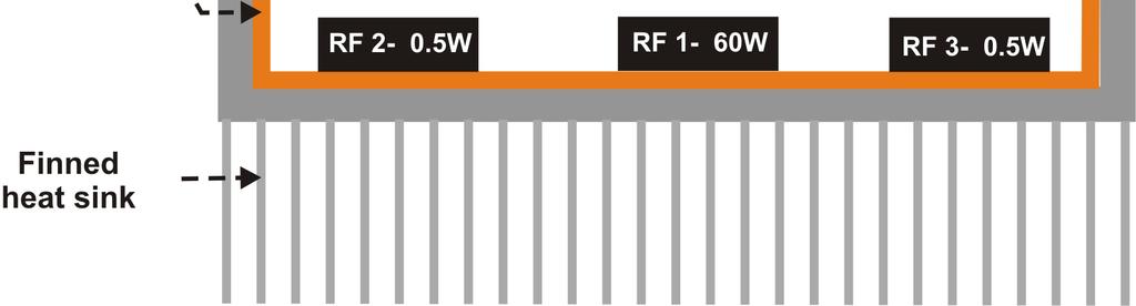
5 pipes can also be used to conduct heat far away from the heat source and be located at the chip or rack level to control the temperature in for example telecommunication cabins. This paper investigates arrangements to improving thermal performance of an original cooling aluminium enclosure used in telecommunication systems through CFD analysis. The investigation includes the use of solid copper as well as vapour chamber heat pipes as supporting shelves for electronic PCBs. 2. Description of the benchmark electronics cooling system The presented RF components cooling system was built as part of a larger telecommunication control system, which would contain hundreds of such units. However, for the purpose of this analysis, only one cooling enclosure unit would be considered here. As shown in Figure 1, each unit was made up of a 55 x 55 mm sealed aluminium enclosure that houses two PCBs located on two separate shelves. Four heat generating electronic chips with varying heat load ratings were supported: one DC power electronic component of 15 W located on the upper shelf and three RF components mounted on the lower shelf with one component rated at 60 W and two other identical components each rated at 0.5 W. In the original design, the PCBs were mounted on a 1 mm copper base material to conduct heat generated in the electronic component to the aluminium enclosure. As well as being a heat sink, the enclosure is also used as a shield to protect against electrical interferences with the RF components circuits. Hence heat transfer from the electronic components to the enclosure occurs through conduction only. A fan and an aluminium finned heat sink assembly was mounted onto the enclosure base to reject heat through forced air convection. To minimise energy consumption of the fan, a speed controller was used to adjust the speed of the fan to deliver accurately the required cooling air flow rates and maintain operating temperature of the 60 W RF components in particular within the design specifications. The power consumption of the fan ranged from 0.03 W, when the electronic components were in standby mode, to 0.5 W at full operation mode which results in high heat rejection rates through the finned heat exchanger. The main steady state operating parameters of the forced air cooling enclosure is shown in Table 1. 3
6 3. CFD modelling of the Benchmark system CFD modelling and simulation has become a routine design tool for predicting accurately thermal performance of electronics cooling systems. The simulation can be a fast and cost effective method to evaluate and optimise heat transfer processes in a wide range of prototype geometries and working conditions. For example, CFD can be used to map temperature distribution on a mounting surface of a PCB with a varied heat generating components and highlight areas where the junction temperature of the semiconductor components could be above the maximum safe temperature specified by the manufacturer. Currently, there are a number of competing commercial CFD packages that can be used, though Flotherm and Icepak are the two main popular packages that are designed specifically for predicting fluid flow and heat transfer in electronic cooling systems [8]. Flotherm is a finite volume based software package that uses simple Cartesian grid meshing. It has a 3D solver for Navier-Stokes equations and equipped with built in boundary conditions for common heat transfer devices and a capability to take into account turbulent flow viscosity losses. The restriction to Cartesian grid meshing, though may enhance convergence, generates a larger grid density. Similarly, Icepak is a finite volume based software package but with much more mesh control capability, enabling meshing of irregular object surfaces. Both packages have a user friendly interface and large library of predefined thermal models for common electronic components/objects such as fans, CPUs, heat sinks, enclosures, PCBs, thermal interface contact resistances, and air flow patterns. This enables fast and accurate design studies to be implemented with detailed graphical information on temperature distribution, fluid flow rates and pressures. Yang [9] showed that both Icepak and Flotherm can yield accurate modelling results for heat transfer in electronics cooling application for laminar and turbulent regimes. However, good knowledge and expertise of heat transfer processes coupled with experimental data may be required to ensure good prediction of results. 4
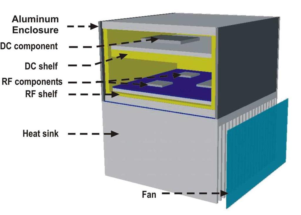
7 In this research, Flotherm was chosen for the design of different cooling strategies of the RF components enclosure. This rectangular shape of the enclosure, shelf components and mounting supports, lend themselves well to meshing using Cartesian coordinates and hence to the use of Flotherm with added advantage of fast converging solution. In this work, the CFD analysis using Flotherm was first conducted on the benchmark system to determine the baseline operating properties. Figure 2 shows a 3-D CFD model of the enclosure and associated component shelves and heat sink. The analysis consists in determining steady state thermal performance of the enclosure, shelves and heat sink to conduct heat away from the heat generating components and maintain a tolerable operating temperature. A Flotherm built-in standard PCB tool was used to model the electronic components. In this tool, the board material and various thermal resistances along the heat transfer path can be specified. All the components were considered to have a layer of solder as an interface with the mounting board. In addition, a thin layer of thermal conductive interface material (Sil Pad and Gap Pad TIM) with a thermal conductivity of 2.0 W/mK was specified for the interfaces between the PCBs, copper shelves, the enclosure frame and the heat sink. A summary of all materials and their operating properties used in the CFD analysis are given in Table DC shelf Figure 3 shows a 3D CFD model of the DC shelf and its cross section. The PCB material was made up of a woven fibreglass material and impregnated with a Flame Retardant 4 (FR4) material. This grade of PCB material is manufactured from multilayer glass fibre epoxy laminates bonded together and has a thickness of 1.6 mm and a glass transient temperature of 135 o C [10 ]. FR4 is a stronger substrate and resistant to cracking or breaking with excellent manufacturing and operating characteristics. It is usually found in higher end electronics and is readily available on short lead-time [11]. An array of copper plated thermal vias was incorporated into the RF4 PCB material directly underneath the DC power electronic component. The copper plated thermal vias occupy an area of 19 x 14 mm and serve to augment heat conduction from the heat source 5
8 to copper base below the PCB. The thermal resistance of an individual via can be calculated from the via radius, the via length between the heat source and the copper spreader plate, and the plating thickness [12, 13]: R via = π k l via 2 2 ( r r ) o 1 where r o is the via drill radius, r 1 the via inner radius, l via the via length, and k the thermal conductivity of copper. The effective thermal resistance of the via array can be calculated from individual thermal resistances connected in parallel. This is given as: 1 = Reff 1 R via i n 1 (2) Using equation 1 and 2, the effective thermal resistance of the via array can be calculated. Therefore inserting the number of vias of 187, the length of 1.6 mm, diameter of 0.8 mm and a plating thickness of 0.05 mm, Equation 1 and 2 yield as a first approximation the thermal resistance of an individual via and the via array of o C/W and 0.19 o C/W respectively. In addition the effective thermal conductivity of the entire area, A, under the DC power electronic component can be evaluated as: K eff lvia = (3) R A eff Using equation 3, the effective thermal conductivity of the area with thermal via array is approximately W/mK. This represents a large improvement compared to the PCB thermal conductivity of 0.6 W/mK (1) 3.2 RF components lower shelf and heat sink The RF components were located on the lower shelf (i.e., the base) of the enclosure to which a finned aluminium heat sink was attached. Figure 4 show a 3D CFD model of the lower shelf and heat sink assembly and a cross of the assembly respectively. As can be seen from the figure, the heat generated from the RF components needs to be conducted through three different layers before it can be rejected away in the 1 mm thick copper spreader: a thin solder layer, an aluminium PCB and a TIM. A layer of a dielectric material above the aluminium PCB was deployed to ensure good electrical isolation of the electronic circuits. 6
9 The dielectric material has a dielectric constant in the range of 4.1 to 4.2 and a dissipation factor of to There are no thermal vias used in the lower shelf PCB. The heat sink was modelled using Flotherm heat sink smart part, which allows specifying the dimensions of the base, fin height, pitch, and thickness. The heat sink CFD model employed a grid of at least three cells between each fin to enable enough resolution for the solver to develop accurate temperature profiles. The fan speed was adjusted so that it can deliver a constant volumetric flow rate of 11 m 3 /h at a pressure difference of 4 Pa and a cooling air temperature of 40 o C. In this analysis, it was assumed that heat transfer by radiation is negligible. 3.3 Benchmark model CFD results The steady state thermal performance analysis of the electronics enclosure with respective heat sources operating at full load was performed using Flotherm. The main consideration was to identify that the temperature limits of the DC and RF components PCBs were not exceeded under the benchmark operating conditions. Figure 5 shows a front view section of the enclosure temperature gradient slicing through the DC power electronic component. It can be seen that the highest temperature occurred at the DC component with a maximum of about 101 o C. Though this is slightly below the maximum allowed operating temperature limit of 110 o C, as specified in Table 1, nevertheless it is still high for safe and steady state operation. Figure 6 shows a side view section of the enclosure temperature. It can be seen that the highest temperature occurred at the 60W RF component. The component temperature reached o C which is 2.85 o C above the maximum temperature limit of the PCB. The temperature of RF component 2 and 3 were approximately 82 o C which is below the specified temperature limit of 135 o C. Overall the simulation shows that the system would fail due to inadequate heat dissipation mechanism of RF component 1 and possibly the DC component of the benchmark model. 7
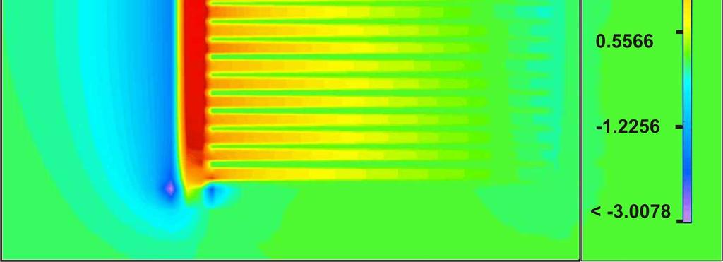
10 Finally, the heat conducted to the enclosure casing must be rejected away through the fan heat sink assembly. The energy consumption of the fan is directly related to the pressure drop and air flow rate. Hence the airflow velocity and pressure drop in the finned heat exchanger was modelled using Flotherm. Figure 7 shows simulation results of cooling air speed fields as it travels through the heat sink fins. It can be seen that the maximum air flow speeds are found at the base of the heat sink inlet (red arrows) as cooling air is circulated across the narrow heat sink fins by a fan. Similarly, Figure 8 shows a mapping of air flow pressure distribution in the heat sink with expected high pressure drops occur near the air inlet at the heat sink base. From the above results, it became clear that the benchmark design needs significant improvement to the heat dissipation process that prevents excessive overheating and ultimately failure of the electronic components. Hence the following section describes the design changes to the heat transfer elements and the thermal merit of each alternative. 4. Design Improvements Taking the benchmark design as the starting point, the effect of the following design strategies were assessed using CFD analysis. Throughout the CFD analysis, the cooling air flow rate of the electronics enclosure heat sink and the ambient air temperature were held constant at 11m 3 /h and 40 o C respectively. All CFD simulation results are summarised in Figure 9 for all the design options given in the following sections with 4.1 Effect of increasing the RF components copper base plate thickness In the benchmark model, the heat generated by the 60 W RF component created a hot spot on the PCB with a temperature higher than the PCB s temperature limit of 135 o C. As a first option, the effect of increasing the thickness of the copper base plate from 1 mm to 3 mm was considered. This should aid to spread and conduct heat more effectively from the heat source to the heat sink. The CFD simulation results of this design are given in column three of Figure 9. It is shown that little effect on the temperature of 60 W RF component had been achieved. This in effect was still about 2 o C above the PCB s maximum operating 8
11 temperature. On the other hand, the temperature of all other RF components on the same PCB was in compliance with the design specification. 4.2 Effect of replacing the RF components copper base plate with a 3 mm thick Vapour Chamber Advanced thermal management solutions in electronics cooling often employ a two-phase fluid for heat transfer using heat pipes. These are high heat conduction devices that take advantages of latent heat of a working fluid as it undergoes phase change. A standard tubular heat pipe is usually the simplest and cheapest configuration of such as a device. However, for this application, shape adaptation to accommodate the flat mounting surfaces of electronic components would be required using for example a flat copper or aluminium solid plate onto which a PCB can be place on. This would defeat the purpose of using a heat pipe as an effective heat transfer mechanism. Therefore, more specialised heat transfer devices as a direct substitute for the solid mounting copper base such VC, also known as flat plate heat pipe, could be more effective. A VC is made up of a sealed flat thermal conductive shell such as copper onto which an electronics PCB can be mounted directly. Heat generated from the multiple electronic components, which were assumed to be uniformly heat source, is then conducted away from the evaporator surface to the condenser. VCs have the advantage of spreading heat over the entire evaporator surface eliminating hot spots appearing under single heat generating components. The proposed VC schematic for this paper is shown in Figure 10, where it can be seen that there are two 0.5 W and one 60W heat generation rate RF components mounted on the evaporator surface. The inner wall of the evaporator has a sintered layer of wick material that is saturated with water as the working fluid. The design of a VC is greatly dependent on a specific thermal application and the proposed VC modelling was carried out using Flotherm simulation package. The simulation combines both thermal and hydraulic properties of the VC. The thermal part defines the heat transfer from the RF components to the VC working fluid (water) and then from the working fluid to the condenser. The heat transfer from the evaporator into the VC causes 9
12 the working fluid to evaporate off the sintered wick layer and the vapour to condense on the condensers surface with resulting heat being conducted away thorough the condenser wall. Similarly, the hydrodynamic simulation characterises the working fluid flow in the wick as it is returned from the condenser to the evaporator through the acting capillary forces. It was assumed that the working flow in the wick is in laminar regime. The Flotherm model was built using Standard Cuboids and Prism elements for the VC copper shell of 55 x 55mm and 3 mm thick, a 0.5 mm wick layer and a vapour space of 1mm high. Then Resistance Object model was used to define the thermal properties of each object. This is a useful tool where the thermal resistance of an object can be inserted manually or determined from other thermal parameters of the object such as thermal conductivity and heat transfer coefficients. It is established that the thermal resistance of the wet wick layer is the most significant resistance for heat transfer in a VC [14]. Experimental tests at Thermacore Inc [15] and elsewhere has found that the effective thermal conductivity of the liquid saturated wick is an order of magnitude less than bulk wick material. For example a copper/water sintered wick layer has conductivity of about 10% that of bulk copper material (i.e., an effective thermal conductivity of 40 W/m K) [15, 16]. On the other hand, the temperature drop associated with the vapour flow could be assumed to be negligible, resulting in a high thermal conductivity of the vapour channel. In the current model an effective thermal conductivity of the vapour space was assumed to be 30,000 W/mK, though similar studies suggest that a thermal conductivity of approximated as 50,000 W/m K can be used [15]. The results of the CFD simulation with a VC was used as a mounting shelf of the RF components PCB are presented in column 4 of Figure 9. It is shown that the VC reduced the temperature of the 60W RF component to o C, which is 5.4 o C better than the benchmark model (column 2) or about 2 o C below the PCB s maximum operating temperature. The simulation results of this design however show that despite the use of VC as an effective heat spreader, heat removal from the electronics enclosure is still inadequate. 10
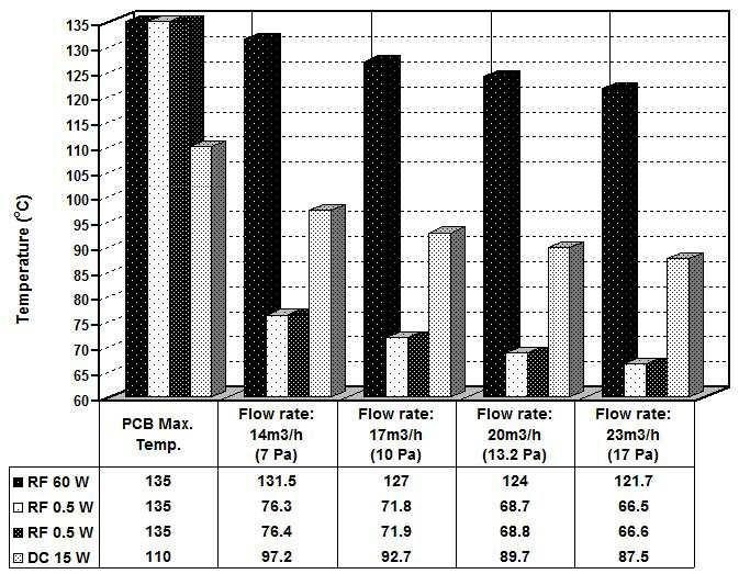
13 4.3 Effect of replacing the enclosure shelves with VCs The improvement to heat transfer of the electronics enclosure provided by the VC in the previous design led to considering the use of a VC unit for the DC shelf as well. The CFD simulation results for this case, presented in the last column of Figure 9, however show that only about 2 o C in temperature drop of the DC shelf would be achieved while the temperature of the FR components was unaltered. This suggests that incorporating an advanced spreading VC device to remove heat from the 15W DC component located on the top shelf is not cost effective. Hence a further investigation was considered to assess the effect of increasing the heat sink airflow rate. For a comparative study, this was conducted for an enclosure with a 3 mm copper and a 3mm VC mounting base for the PCB of the RF components. 4.4 Effect of increasing enclosure heat sink airflow rates Simulation results of varying airflow rate over the aluminium heat sink fins was conducted in a similar way as described previously. This was achieved by controlling the speed of the heat sink fan to increase the airflow rate by equal increments of 3 m 3 /h from the benchmark case of 11 m 3 /h to a maximum of 23 m 3 /h. Figure 11 shows the CFD simulation results of increasing cooling airflow rate for the case of an enclosure with a 3 mm solid copper RF components shelf. It shows that the operating temperature of all RF components decreased proportionally with increasing cooling airflow rate. The operating temperature of the 60W RF components dropped to o C for flow rates of 23 m 3 /h, which is 13.3 o C below the PCB maximum operating temperature. This shows that the cooling air flow rate of the benchmark model was not adequately optimised, resulting in RF components having temperatures above the PCB s operating temperature limit. Increasing the enclosure heat sink air flow rates was however accompanied by an increase in fan power from 0.07 in case of the benchmark model to 0.4 W for flow rate of 23 m 3 /h, that is 22.5 % increase in energy consumption. 11
14 A similar simulation was performed for the case of substituting the copper shelf with a VC shelf. The results of this simulation are shown in Figure 12. It is shown that a similar trend of decreasing the temperature of all RF components with increased air flow rates was observed. Consistent with results obtained in the benchmark case for flow rate of 11m3/h, the VC exceeded the thermal performance of the solid copper shelf at all flow rates. For instance, at flow rates of 23 m 3 /h, the operating temperature of the powerful 60W RF components dropped to o C which is 18.5 o C below the PCB maximum operating temperature. This shows that the overall thermal performance of the VC shelf unit is marginally better than the 3mm solid copper base for all flow rates. The operating temperature of the RF components was on average 5.4 o C lower when mounted on a VC shelf. The thermal performance of a VC is application specific; however the evaporation and condensation process of the working fluid ensures a faster energy transfer from the heat generating electronic components to the heat sink, with the liquid flow in the wick contributing to spreading evenly the heat over a larger area. Previous research works showed that VC use as advanced thermal management solution in electronics cooling has always outperformed solid copper or aluminium materials of similar dimensions. Sonan et al. [17] studied the transient performance of a 40 x 40 x 0.9 mm flat heat pipe used to cool multiple electronics components. A solid copper base of similar size was used to compare the cooling capability of the VC and it was shown that the maximum temperature difference between the hottest electronic component and the condenser was higher on the copper plate than on the VC by 11 K. The authors previous work on large VCs [7] showed that on most cases VCs outperform solid copper as a mounting base for cooling electronics. The authors found that the VC has the ability to generate a more uniform temperature distribution across the evaporator surface than the solid copper plate and measured temperature difference at the component level of up to 15 o C higher on solid copper plate that on a VC. The thermal cooling performance improvement brought about by substituting the solid copper shelf by a VC in this work was marginally lower than that reported in previous work. 12
15 However, it is difficult to make exact comparison as testing and operating the VC may not be carried out under similar conditions. For example heat transfer from the electronic components to the heat sink occurs through a PCB, TIMs and the enclosure wall, increasing the overall thermal resistance. Furthermore, imposed ambient cooling air temperature of 40 o C as a design constraint had a limiting effect on rate of heat removal from the heating generating RF components. 4.5 CFD simulation accuracy A mesh sensitivity analysis was performed in order to determine the accuracy of the results of the Flotherm simulations. This was carried out by varying the mesh density of a typical CFD model with 250,000 mesh counts. Two mesh counts of 35,000 and 500,000 were considered for which simulation solutions in terms of RF component temperatures are given in Table 3. It is shown that compared to the typical mesh count model (column 4), the high mesh count simulation results were o C higher whereas for the low mesh count the difference was o C, an accuracy range of 0.1% to 2.90%. Hence there is little to be gained by increasing the mesh count to 500,000 mesh counts as this will required more computation resources and processing time. 5 Conclusions This paper presented a CFD simulation of an electronics enclosure cooling system to be used as part of a larger radar control system. The device contained two PCBs housed within an Aluminium enclosure with each PCB mounted on a copper shelf to help spread heat generated from the RF components. The highest power rating RF component was rated at 60 W and located on the lower shelf of the enclosure, which in turn was in contact with a forced air convection aluminium heat sink. The top shelf (DC component) houses a 15W power electronic component. A parametric performance investigation showed that the original design was unsatisfactory, as the 60W RF component operating temperature exceeded the maximum limit safe limit of the PCB. Therefore, improved designs were suggested and the impact of each design variant on thermal performance of the cooling enclosure was modelled. The studied design 13
16 configurations include use of a 3 mm copper shelve, a 3 mm VC for the RF components shelf, a 3 mm VC for both the RF components and DC shelves, and increasing the cooling air flow rate of the heat sink. The following is a summary of the main results obtained in this investigation. i) In the original benchmark model, one of the main problems was overheating of the 60W RF component PCB. It was found that inadequate heat removal from the electronic component caused the temperature to be 3.5 o C over the design temperature limit of the PCB material. ii) The initial solution was to increasing the thickness of the copper slice of the RF components from the original design of 1 mm to 3 mm. this reduced the temperature of the 60W component by 1.5 o C only, that is still 2 o C over the design temperature limit of the PCB material. iii) A more advanced thermal management solution was contemplated by substituting the copper shelf of the RF components with a 3 mm VC. This showed that the temperature of the 60W RF component can be reduced by approximately 5.4 o C, bringing the operating temperature below the PCB temperature limit by about 2 o C. iv) Replacing the 15W DC component upper shelf with a VC yielded little change in the component s operating temperature (0.9 o C) which may not be cost effective. v) The final design was a combination of using a 3 mm thick DC upper copper shelf, a 3 mm thick VC lower shelf and increasing the cooling air flow rate of the enclosure heat sink. The operating temperature of electronic components on both shelves decreased at a constant rate by as much as 18.5 o C below the PCB s temperature limit. This however was achieved at the expense of higher fan energy consumption. From the above results it was shown that the deployment of a VC allowed to bring the operating temperature of the 60W RF component within the acceptable PCB temperature limits. It is worth noting that in this paper the consideration of the VC was solely to 14
17 investigate the technical merit of the deployment of the technology as an effective thermal management solution in electronics cooling. Hence the economic analysis was not part of the study. The high heat conduction and thermal spreading properties of a VC allows increasing the density of electronic components of different power ratings that can be mounted on a single PCB without the risk of developing hot spots or causing thermal interface between adjacent components, making RF components housing units more compact. This may present an advantage over using a large number of PCBs mounted on separate shelves and offset the high manufacturing cost associated with the VC technology. Acknowledgments The authors wish to thank EPSRC (Engineering and Physical Sciences Research Council, UK) for their financial support of the project under GrantEP/P500389/1 and Themacore Europe Ltd for providing financial and technical help. References [1] D. A. Reay, P. A. Kew, Heat Pipes: Theory, Design and applications, Fifth edition, Butterworth-Heinemann, New York,
18 [2] A.G. Agwu Nnanna, Application of refrigeration system in electronics cooling, Applied Thermal Engineering 26 (2006) [3] H. Lee, Y. Jeong, J. Shin, J. Baek, M. Kang, K. Chun, Package embedded heat exchanger for stacked multi-chip module, Sensors and Actuators A 114 (2004) [4] R.R. Schmidt, H. Shaukatullah, Computer and telecommunications equipment room cooling; a review of literature, IEEE Transactions on Components and Packaging Technologies 26 (1) (2003) [5] C. W. Leung, H. J. Kang, S. D. Probert, Horizontal simulated printed-circuit board assembly in fully-developed laminar-flow convection, Applied Energy, 56 (1) (1997) [6] Z. Radivojevic, et al., Operating limits for RF power amplifiers at high junction temperatures, Microelectronics Reliability 44 (2004) [7] R. Boukhanouf et al., Experimental investigation of a flat plate heat pipe performance using IR thermal imaging camera, Applied Thermal Engineering, 26 (17-18) (2006) [8] M. C. Yang, A comparison of using Icepak and Flotherm in electronic cooling, The Seventh Intersociety Conference on Thermal and Thermomechanical Phenomena in Electronic Systems (ITHERM) 1 (2000) , May 23-26, Las Vegas, Nevada [9] R. Remsburg, Advanced thermal design of electronic equipments, Chapman and Hall, New York, 1998 [10] L. Coppola, D. Cottet, F. Wildner, Investigation on current density limits in power printed circuit boards, Applied Power Electronics Conference and Exposition (APEC) (2008) , Austin, Texas. 16
19 [11] P. Arulvanan and Z.W. Zhong, Assembly and reliability of PBGA packages on FR4 PCBs with SnAgCu solder, Microelectronic Engineering 83 (2006) [12] C. F. Coombs, Printed Circuits Handbook, Sixth edition, McGraw-Hill, New York, [13] R. K. Setty, K. Kiew, H. Kaylie, Commercial-off-the-shelf MMIC components offer high reliability, RF Design, (2005) [14] J. Liou., C. Chang, C. Chao and S. Wong, Visualization and thermal resistance measurement for the sintered mesh-wick evaporator in operating flat-plate heat pipes, International Journal of Heat and Mass Transfer, 53 (7-8) (2010) [15] K. Grubb, CFD Modeling of a Therma-BaseTM Heat Sink, Thermacore, Inc., available from (2009). [16] Y. Chen, K. Chien, T. Hung, C. Wang, Y. Ferng and B. Pei, Numerical simulation of a heat sink embedded with a vapor chamber and calculation of effective thermal conductivity of a vapor chamber, Applied Thermal Engineering, 29 (13) (2009) [17] R. Sonan a, S. Harmand a,*, J. Pellé a, D. Leger a, M. Fakès, Transient thermal and hydrodynamic model of flat heat pipe for the cooling of electronics components, International Journal of Heat and Mass Transfer 51 (2008) List of Figures Figure 1 A schematic representation of electronics cooling enclosure Figure 2 Layout of the benchmark model 17
20 Figure 3 DC upper shelf layout and cross section Figure 4 Lower shelf layout and cross section Figure 5 Cooling enclosure front view temperature gradient Figure 6 Cooling enclosure side view temperature gradient Figure 7 Air flow velocity distribution in the heat sink Figure 8 Pressure distribution in the heat sink Figure 9 Effect of varying shelf thickness and material Figure 10 Cross section of a vapour chamber model Figure 11 Effect of varying the heat sink air flow rate for the 3 mm copper RF components shelf Figure 12 Effect of varying the heat sink airflow rate for the 3 mm VC RF components shelf List of Tables Table 1 Overview of the cooling enclosure system specification Table 2 Dimension and thermal properties of the cooling system elements Table 3 Effect of mesh count on CFD simulation accuracy 18
21 Table 1 Enclosure Material Aluminium Dimension 55 x 55 mm Wall thickness 3 mm Number of shelves 2 Heat sink Base area 55 mm x 55 mm Base thickness 3 mm Number of fins 18 Fin height 30 mm Fin width 1 mm PCB Thermal Component Heat rating Temperature Limit Base dimension resistance Description (W) ( o C) (mm) ( o C/W) RF x 13 RF x 10 RF x 10 DC x 19 1
22 Table 2 Element Symbol Element Thickness Thermal conductivity (mm) (W/mK) Dielectric substrate Tin Solder layer PCB Thermal via circuit TIM RF copper shelf Aluminium Box
23 Table 3 PCB Power (W) 35,000 mesh counts 250,000 mesh count (performed simulation) 500,000 mesh counts Simulation accuracy range RF to 2.90 RF to 2.30 RF to 2.08 DC to 0.40 (%) 1

24
25

26

27


28


29


30

31

32

33
34

35
Continuous melting and pouring of an aluminum oxide based melt with cold crucible
 Continuous melting and pouring of an aluminum oxide based melt with cold crucible B Nacke, V Kichigin, V Geza, I Poznyak To cite this version: B Nacke, V Kichigin, V Geza, I Poznyak. Continuous melting
USING INTEGRATED PLANAR THERMOSYPHON PCBs TO ENHANCE COOLING OF HIGH BRIGHTNESS LEDs
 USING INTEGRATED PLANAR THERMOSYPHON PCBs TO ENHANCE COOLING OF HIGH BRIGHTNESS LEDs High power LED lighting systems bring with them a lot of promise and numerous challenges. The advantages of LED lamps
Smart Integration of Thermal Management Systems for Electronics Cooling
 Smart Integration of Thermal Management Systems for Electronics Cooling Dr. Ir. Wessel W. Wits, University of Twente, Faculty of Engineering Technology, Laboratory of Design, Production and Management,
CHAPTER-1 INTRODUCTION
 CHAPTER-1 INTRODUCTION 1.1 COOLING OF ELECTRONIC EQUIPMENTS: In general, the sole objective of improving the cooling of electronic systems is to increase cooling capacity. The failure rate of electronic
Characterization of a semi-indirect evaporative cooler
 Characterization of a semi-indirect evaporative cooler R. Herrero Martín To cite this version: R. Herrero Martín. Characterization of a semi-indirect evaporative cooler. Applied Thermal Engineering, Elsevier,
Energy savings potential using the thermal inertia of a low temperature storage
 Energy savings potential using the thermal inertia of a low temperature storage D. Leducq, M. Pirano, G. Alvarez To cite this version: D. Leducq, M. Pirano, G. Alvarez. Energy savings potential using the
Collusion through price ceilings? In search of a focal-point effect
 Collusion through price ceilings? In search of a focal-point effect Dirk Engelmann, Wieland Müllerz To cite this version: Dirk Engelmann, Wieland Müllerz. Collusion through price ceilings? In search of
Impact of cutting fluids on surface topography and integrity in flat grinding
 Impact of cutting fluids on surface topography and integrity in flat grinding Ferdinando Salvatore, Hedi Hamdi To cite this version: Ferdinando Salvatore, Hedi Hamdi. Impact of cutting fluids on surface
Electronics Cooling Products
 Advanced Cooling Technologies, Inc. Electronics Cooling Products Military Electronics Power Electronics Industrial Electronics Products Services Technologies Electronics Cooling Products Heat Pipe Assemblies
Prediction of the energy efficiency of an Ar-H2-O2 plasma torch with Ansys Fluent
 Prediction of the energy efficiency of an Ar-H2-O2 plasma torch with Ansys Fluent M Vadon, Y Delannoy, G Chichignoud To cite this version: M Vadon, Y Delannoy, G Chichignoud. Prediction of the energy efficiency
Heat Optimisation of Processor Cooling by Varying casing Material
 e t International Journal on Emerging Technologies (Special Issue NCETST-2017) 8(1): 702-706(2017) (Published by Research Trend, Website: www.researchtrend.net) ISSN No. (Print) : 0975-8364 ISSN No. (Online)
NOVEL MATERIALS FOR IMPROVED QUALITY OF RF-PA IN BASE-STATION APPLICATIONS
 Novel Material for Improved Quality of RF-PA in Base-Station Applications Co-Authored by Nokia Research Center and Freescale Semiconductor Presented at 10 th International Workshop on THERMal INvestigations
Performance Improvement of a Micro Channel Heat Sink
 Performance Improvement of a Micro Channel Heat Sink Guthula Satish Mr. K Bala Murali Krishna Mr. D Kishor Babu ABSTRACT: Thermal management of components is the most important consideration for electronic
The Effect of Magnetic Field on Metal Anodizing Behaviour
 The Effect of Magnetic Field on Metal Anodizing Behaviour T Kozuka, H Honda, S Fukuda, M Kawahara To cite this version: T Kozuka, H Honda, S Fukuda, M Kawahara. The Effect of Magnetic Field on Metal Anodizing
Study of High Power COB LED Modules with Respect to Topology of Chips
 Study of High Power COB LED Modules with Respect to Topology of Chips Nikolay Vakrilov 1), Anna Andonova 1), and Nadejda Kafadarova 2) 1) FEET, Technical University of Sofia, Sofia, Bulgaria 2) Faculty
An evaluation of ground thermal properties measure accuracy by thermal response test of horizontal ground heat exchangers
 An evaluation of ground thermal properties measure accuracy by thermal response test of horizontal ground heat exchangers Mikael Philippe, Dominique Marchio, Hervé Lesueur, Alexandre Vrain To cite this
Effects of temperature on monotonic and fatigue properties of carbon fibre epoxy cross ply laminates
 Effects of temperature on monotonic and fatigue properties of carbon fibre epoxy cross ply laminates Y. Matsuhisa, J. King To cite this version: Y. Matsuhisa, J. King. Effects of temperature on monotonic
Thermal Stress Failures: A New Experimental Approach For Prediction and Prevention
 Thermal Stress Failures: A New Experimental Approach For Prediction and Prevention M. Hertl, R. Fayolle, D. Weidmann, J.-C. Lecomte To cite this version: M. Hertl, R. Fayolle, D. Weidmann, J.-C. Lecomte.
Thermal management of lateral GaN power devices
 Thermal management of lateral GaN power devices Chenjiang Yu, Éric Labouré, Cyril Buttay To cite this version: Chenjiang Yu, Éric Labouré, Cyril Buttay. Thermal management of lateral GaN power devices.
New method to evaluate the heat storage density in latent heat storage for arbitrary temperatureranges
 New method to evaluate the heat storage density in latent heat storage for arbitrary temperatureranges H. Mehling, S. Hiebler, E. Günther To cite this version: H. Mehling, S. Hiebler, E. Günther. New method
Development of Plasma Heating and Electromagnetic Stirring in Tundish
 Development of Plasma Heating and Electromagnetic Stirring in Tundish Emmanuel Abiona, Hongliang Yang, Rajneesh Chaudhary, Ravi Kumar Kandasamy, Jan-Erik Eriksson To cite this version: Emmanuel Abiona,
Download this article in.pdf format This file type includes high resolution graphics and schematics when applicable.
 1 of 5 7/15/2015 3:06 PM print close Electronic Design Terry Luxmore, Kent Roff and Leon Lu, CTS Corp. Wed, 2015-06-17 15:02 Lighting products based on light-emitting diodes (LEDs) are gaining a stronger
Composite Simulation as Example of Industry Experience
 Composite Simulation as Example of Industry Experience Joachim Bauer To cite this version: Joachim Bauer. Composite Simulation as Example of Industry Experience. George L. Kovács; Detlef Kochan. 6th Programming
Fluid Flow and Heat Transfer Analysis in AaParallel Plate Heat Sink Using a Commercial CFD Software
 International Journal of Pure and Applied Physics ISSN 0973-1776 Volume 4, Number 2 (2008), pp. 97 104 Research India Publications http://www.ripublication.com/ijpap.htm Fluid Flow and Heat Transfer Analysis
Investigation of Vapour Chamber Performance with a Concentrated Heat Source
 Journal of Physics: Conference Series OPEN ACCESS Investigation of Vapour Chamber Performance with a Concentrated Heat Source To cite this article: E Ravache et al 2014 J. Phys.: Conf. Ser. 525 012005
Performance Improvement on Water-cooled Cold-Plate
 Proceedings of the 4th WSEAS International Conference on Heat and Mass Transfer, Gold Coast, Queensland, Australia, January 17-19, 2007 104 Performance Improvement on Water-cooled Cold-Plate SHYAN-FU CHOU,
Numerical Analysis of Heat Pipe Fin Stack by Delta Wing Vortex Generator
 Numerical Analysis of Heat Pipe Fin Stack by Delta Wing Vortex Generator #1 Diksha D Nadkarni, #2 Dr.R.R.Arakerimath 1 Student, Mechanical Department, Pune University, India 2 Professor, Mechanical Department,
Experimental Study on Forced-Air Precooling of Dutch Cucumbers
 Experimental Study on Forced-Air Precooling of Dutch Cucumbers Jingying Tan, Shi Li, Qing Wang To cite this version: Jingying Tan, Shi Li, Qing Wang. Experimental Study on Forced-Air Precooling of Dutch
Thermal Performance of Thermoelectric Cooler (TEC) Integrated Heat Sink and Optimizing Structure for Low Acoustic Noise / Power Consumption
 Integrated Heat Sink and Optimizing Structure for Low Acoustic Noise / Power Consumption") Thermal Performance of Thermoelectric Cooler () Integrated Heat Sink and Optimizing Structure for Low Acoustic Noise / Power Consumption Masami Ikeda, Toshiaki Nakamura, Yuichi Kimura, Hajime Noda The
Thermal Performance of Thermoelectric Cooler () Integrated Heat Sink and Optimizing Structure for Low Acoustic Noise / Power Consumption Masami Ikeda, Toshiaki Nakamura, Yuichi Kimura, Hajime Noda The
Methods for Evaluating Advanced Electronics Cooling Systems
 A W H I T E WP AH PIE TR EF R OP MA AP N ES YR S, I N C. Methods for Evaluating Advanced Electronics Cooling Systems Hossam Metwally, PhD Senior Consulting Engineer, Electronics Industry Fluent Inc. ABSTRACT
Optimization of operating conditions of a mini fuel cell for the detection of low or high levels of CO in the reformate gas
 Optimization of operating conditions of a mini fuel cell for the detection of low or high levels of CO in the reformate gas Christophe Pijolat, Guy Tournier, Jean-Paul Viricelle, Nicolas Guillet To cite
BLDC Motor for Automotive Cooling Fan Assembly: Heat Sink Optimization
 BLDC Motor for Automotive Cooling Fan Assembly: Heat Sink Optimization Davide Parodi Fluid Dynamic and Aeroacoustic Engineer, Automotive Product Group, Johnson Electric Asti S.r.l. Asti, Italy Email: davide.parodi@johnsonelectric.com
THERMAL PULSE ANNEALING OF TITANIUM AND TANTALUM SILICIDES
 THERMAL PULSE ANNEALING OF TITANIUM AND TANTALUM SILICIDES P. Rosser, G. Tomkins To cite this version: P. Rosser, G. Tomkins. THERMAL PULSE ANNEALING OF TITANIUM AND TAN- TALUM SILICIDES. Journal de Physique
Thermal analysis and optimization of heat sink
 IOSR Journal of Mechanical and Civil Engineering (IOSR-JMCE) e-issn: 2278-1684,p-ISSN: 2320-334X PP. 17-21 www.iosrjournals.org Shashidhar N S 1, Balaji D Tandle 2 1 (Department of Mechanical, Sr. Application
Finite Element Model of Gear Induction Hardening
 Finite Element Model of Gear Induction Hardening J Hodek, M Zemko, P Shykula To cite this version: J Hodek, M Zemko, P Shykula. Finite Element Model of Gear Induction Hardening. 8th International Conference
CFD Modelling and Analysis of Different Plate Heat Exchangers
 CFD Modelling and Analysis of Different Plate Heat Exchangers Ahmed Y Taha Al-Zubaydi a *, Guang Hong b and W. John Dartnall c Faculty of Engineering and Information Technology, UTS, Sydney, Australia
NANOINDENTATION-INDUCED PHASE TRANSFORMATION IN SILICON
 NANOINDENTATION-INDUCED PHASE TRANSFORMATION IN SILICON R. Rao, J.-E. Bradby, J.-S. Williams To cite this version: R. Rao, J.-E. Bradby, J.-S. Williams. NANOINDENTATION-INDUCED PHASE TRANSFORMA- TION IN
Conception of a new engineering curriculum in smart buildings
 Conception of a new engineering curriculum in smart buildings Anne-Marie Jolly, Christophe Léger, Guy Lamarque To cite this version: Anne-Marie Jolly, Christophe Léger, Guy Lamarque. Conception of a new
Progress of some techniques on electromagnetic metallurgy
 Progress of some techniques on electromagnetic metallurgy Engang Wang To cite this version: Engang Wang. Progress of some techniques on electromagnetic metallurgy. 8th International Conference on Electromagnetic
Abstract. 1. Introduction
 CFD Analysis of Splayed Pin Fin Heat Sink for Electronic Cooling Agnihothra Sarma O 1, A Ramakrishna 2 PG Student 1, Professor 2 Department of Mechanical Engineering, BVC Engineering College, Odalarevu
Heat Transfer Correlations for Low Approach Evaporative Cooling Systems in Buildings
 Heat Transfer Correlations for ow Approach Evaporative Cooling Systems in Buildings B. Costelloe, D.P. Finn To cite this version: B. Costelloe, D.P. Finn. Heat Transfer Correlations for ow Approach Evaporative
Multiple-Layer Heat Dissipation Module for LED Streetlamps
 Journal of Applied Science and Engineering, Vol. 15, No. 2, pp. 97 104 (2012) 97 Multiple-Layer Heat Dissipation Module for LED Streetlamps Shung-Wen Kang*, Kun-Cheng Chien and Wei-Chung Lin Department
Selecting the components of composites
 Selecting the components of composites M. Ashby To cite this version: M. Ashby. Selecting the components of composites. Journal de Physique IV Colloque, 1993, 03 (C7), pp.c7-1595-c7-1600. .
Spray cooling of IGBT electronic power modules
 Thermal Challenges in Next Generation Electronic Systems, Joshi & Garimella (eds) 2002 Millpress, Rotterdam, ISBN 90-77017-03-8 G. Mitic, W. Kiffe, G. Lefranc, S. Ramminger Siemens AG, Corporate Technology
COOLING SOURCE - THE DIFFERENCE
 COOLING SOURCE - THE DIFFERENCE MISSION STATEMENT Cooling Source aims to deliver the highest value of services and products in a timely manner to our customers as the premier thermal solutions manufacturer,
Moisture Measurements in PCBs and Impact of Design on Desorption Behaviour
 Moisture Measurements in PCBs and Impact of Design on Desorption Behaviour Chris Hunt, Owen Thomas & Martin Wickham National Physical Laboratory Teddington, UK Abstract High levels of residual moisture
Investigation on the Impact on Thermal Performances of New Pin and Fin Geometries Applied to Liquid Cooling of Power Electronics
 Investigation on the Impact on Performances of New Pin and Fin Geometries Applied to Liquid Cooling of Power Electronics Matt Reeves, Jesus Moreno, Peter Beucher, Sy-Jenq Loong and Dwight Brown. MicrooCool
CHAPTER 2 LITERATURE REVIEW
 13 CHAPTER 2 LITERATURE REVIEW 2.1 INTRODUCTION The performance of heat sinks has been the focus of many investigations in recent years and the subject has been treated analytically, numerically and experimentally.
PCB Technologies for LED Applications Application note
 PCB Technologies for LED Applications Application note Abstract This application note provides a general survey of the various available Printed Circuit Board (PCB) technologies for use in LED applications.
Cooligy. The Heat Problem. Why Keep CPUs Cool? Active Micro-Channel Cooling. Peak Power Density (Watts/cm 2 ) Total Power (Watts)
 Total Power (Watts)") Active MicroChannel Cooling The Heat Problem 140 120 100 80 60 40 20 0 486 Total Power (Watts) RISC Pentium Pentium 4 Pentium III Next Generation 600 400 300 200 100 Why Keep CPUs Cool? Greater Performance
Active MicroChannel Cooling The Heat Problem 140 120 100 80 60 40 20 0 486 Total Power (Watts) RISC Pentium Pentium 4 Pentium III Next Generation 600 400 300 200 100 Why Keep CPUs Cool? Greater Performance
CFD MODELING AND PARAMETRIC STUDY OF VAPOR CHAMBERS AS HEAT SPREADERS FOR HIGH-POWER ELECTRONIC DEVICES DHANRAJ ARUN PATIL
 CFD MODELING AND PARAMETRIC STUDY OF VAPOR CHAMBERS AS HEAT SPREADERS FOR HIGH-POWER ELECTRONIC DEVICES by DHANRAJ ARUN PATIL Presented to the Faculty of the Graduate School of The University of Texas
The new LSM 700 from Carl Zeiss
 The new LSM 00 from Carl Zeiss Olaf Selchow, Bernhard Goetze To cite this version: Olaf Selchow, Bernhard Goetze. The new LSM 00 from Carl Zeiss. Biotechnology Journal, Wiley- VCH Verlag, 0, (), pp.. .
Heat line formation during roll-casting of aluminium alloys at thin gauges
 Heat line formation during roll-casting of aluminium alloys at thin gauges M. Yun, J. Hunt, D. Edmonds To cite this version: M. Yun, J. Hunt, D. Edmonds. Heat line formation during roll-casting of aluminium
ELECTRONIC PROPERTIES OF SILICON INTERFACES PREPARED BY DIRECT BONDING
 ELECTRONIC PROPERTIES OF SILICON INTERFACES PREPARED BY DIRECT BONDING S. Bengtsson, O. Engström To cite this version: S. Bengtsson, O. Engström. ELECTRONIC PROPERTIES OF SILICON INTERFACES PRE- PARED
Simulation of Dislocation Dynamics in FCC Metals
 Simulation of Dislocation Dynamics in FCC Metals Y. Kogure, T. Kosugi To cite this version: Y. Kogure, T. Kosugi. Simulation of Dislocation Dynamics in FCC Metals. Journal de Physique IV Colloque, 1996,
Thermal behaviour modelling of superplastic forming tools
 Thermal behaviour modelling of superplastic forming tools Vincent Velay, Thierry Cutard, N. Guegan To cite this version: Vincent Velay, Thierry Cutard, N. Guegan. Thermal behaviour modelling of superplastic
Comparison of lead concentration in surface soil by induced coupled plasma/optical emission spectrometry and X-ray fluorescence
 Comparison of lead concentration in surface soil by induced coupled plasma/optical emission spectrometry and X-ray fluorescence Roseline Bonnard, Olivier Bour To cite this version: Roseline Bonnard, Olivier
Design and Analysis of Hydraulic Oil Cooler by Application of Heat Pipe
 Design and Analysis of Hydraulic Oil Cooler by Application of Heat Pipe Abstract Heat pipe is an essentially passive heat transfer device having high thermal conductivity. In hydraulic power pack use of
Induction hardening of small gear wheels made of steel 50CrMo4
 Induction hardening of small gear wheels made of steel 50CrMo4 J Barglik, A Smalcerz, A Smagór To cite this version: J Barglik, A Smalcerz, A Smagór. Induction hardening of small gear wheels made of steel
Power Electronics Packaging Revolution Module without bond wires, solder and thermal paste
 SEMIKRON Pty Ltd 8/8 Garden Rd Clayton Melbourne 3168 VIC Australia Power Electronics Packaging Revolution Module without bond wires, solder and thermal paste For some years now, the elimination of bond
Keeping Cool!: selecting high performance thermal materials for LED Lighting applications. Ian Loader 25/03/14
 Keeping Cool!: selecting high performance thermal materials for LED Lighting applications Ian Loader 25/03/14 1 Target Points to cover Basics of Thermal Management Considerations for thermal materials
COOLING EFFECT ENHANCEMENT IN MAGNETRON SPUTTERING SYSTEM
 Fifth International Conference on CFD in the Process Industries CSIRO, Melbourne, Australia 13-15 December 2006 COOLING EFFECT ENHANCEMENT IN MAGNETRON SPUTTERING SYSTEM Jae-Sang BAEK and Youn J. KIM*
An update on acoustics designs for HVAC (Engineering)
") An update on acoustics designs for HVAC (Engineering) Ken Marriott To cite this version: Ken Marriott. An update on acoustics designs for HVAC (Engineering). Société Française d Acoustique. Acoustics 2012,
An update on acoustics designs for HVAC (Engineering) Ken Marriott To cite this version: Ken Marriott. An update on acoustics designs for HVAC (Engineering). Société Française d Acoustique. Acoustics 2012,
Development of Colorimetric Analysis for Determination the Concentration of Oil in Produce Water
 Development of Colorimetric Analysis for Determination the Concentration of Oil in Produce Water M. S. Suliman, Sahl Yasin, Mohamed S. Ali To cite this version: M. S. Suliman, Sahl Yasin, Mohamed S. Ali.
Theoretical analysis of an integrated thermoelectric-absorption cooling system
 Theoretical analysis of an integrated thermoelectric-absorption cooling system R. Boukhanouf (corresponding author) and A. Supasuteekul School of the Built Environment University of Nottingham, Nottingham,
Fatigue of High Purity Copper Wire
 Fatigue of High Purity Copper Wire N. Tanabe, A. Kurosaka, K. Suzuki, O. Kohno To cite this version: N. Tanabe, A. Kurosaka, K. Suzuki, O. Kohno. Fatigue of High Purity Copper Wire. Journal de Physique
Continuous Casting of Aluminum and Copper Clad Ingots under Electromagnetic Fields
 Continuous Casting of Aluminum and Copper Clad Ingots under Electromagnetic Fields Joonpyo Park, Jong Ho Kim, Myoung Gyun Kim, Young Joon Lee, Tingu Li, Kwang Seok Lee, Jong Sup Lee To cite this version:
CFD SIMULATION AND EXPERIMENTAL VALIDATION OF FLUID FLOW IN LIQUID DISTRIBUTORS
 CFD SIMULATION AND EXPERIMENTAL VALIDATION OF FLUID FLOW IN LIQUID DISTRIBUTORS Marc Heggemann 1, Sebastian Hirschberg 1, Lothar Spiegel 2, Christian Bachmann 2 1 Sulzer Innotec, Sulzer Markets & Technology
Experimental analysis of droplet-gas interaction during GMAW process
 Experimental analysis of droplet-gas interaction during GMAW process Julien Chapuis, Edward Roméro, Fabien Soulié, Cyril Bordreuil To cite this version: Julien Chapuis, Edward Roméro, Fabien Soulié, Cyril
Manual UT vs Permanently Installed Sensors
 Manual UT vs Permanently Installed Sensors Frederic Cegla To cite this version: Frederic Cegla. Manual UT vs Permanently Installed Sensors. Le Cam, Vincent and Mevel, Laurent and Schoefs, Franck. EWSHM
Impact of Heatsink Attach Loading on FCBGA Package Thermal Performance
 Impact of Heatsink Attach Loading on FCBGA Package Thermal Performance Sasanka L. Kanuparthi, Jesse E. Galloway and Scott McCann Amkor Technology 1900 S Price Rd, Chandler, AZ, USA, 85286 Phone: (480)
High Power in Small Spaces: Myths
 Thermal Management of High Power in Small Spaces: Myths and Misconceptions Challenged www.atrenne.com sales@atrenne.com 508.588.6110 800.926.8722 Thermal Management of High Power in Small Spaces: Myths
A Design Method for Product Upgradability with Different Customer Demands
 A Design Method for Product Upgradability with Different Customer Demands Masato Inoue, Shuho Yamada, Tetsuo Yamada, Stefan Bracke To cite this version: Masato Inoue, Shuho Yamada, Tetsuo Yamada, Stefan
Building HDI Structures using Thin Films and Low Temperature Sintering Paste
 Building HDI Structures using Thin Films and Low Temperature Sintering Paste Catherine Shearer, James Haley and Chris Hunrath Ormet Circuits Inc. - Integral Technology California, USA chunrath@integral-hdi.com
A framework to improve performance measurement in engineering projects
 A framework to improve performance measurement in engineering projects Li Zheng, Claude Baron, Philippe Esteban, Rui ue, Qiang Zhang To cite this version: Li Zheng, Claude Baron, Philippe Esteban, Rui
Closed Loop Liquid Cooling for High Power Electronics
 Volume 1 Issue 9 October 2007 The newsletter for the thermal management of electronics 1 In this issue: Future Cooling FUTURE COOLING Closed Loop Liquid Cooling for High Power Electronics 6 Thermal Minutes
Ullage Temperatures in Wet Spent Fuel Transport Flasks.
 Ullage Temperatures in Wet Spent Fuel Transport Flasks. D J Burt*, A R Cory**, S J Graham** and M Myszko* * Rose Consulting Engineers Ltd, 17 Home Farm Avenue, Macclesfield, SK10 3QW, UK. T: +44 (0)1625
Laird Engineered Thermal Systems Application Note. Thermoelectric Modules Accelerate PCR Thermal Cycling
 Laird Engineered Thermal Systems Application Note Thermoelectric Modules Accelerate PCR Thermal Cycling March 2017 Table of Contents Introduction...3 Polymerase Chain Reaction...3 Thermal Cycling...3 Standard
Electrical properties of interlevel deposited oxides related to polysilicon preparation
 Electrical properties of interlevel deposited oxides related to polysilicon preparation C. Cobianu, O. Popa, D. Dascalu To cite this version: C. Cobianu, O. Popa, D. Dascalu. Electrical properties of interlevel
Conceptual Design of an Intelligent Welding Cell Using SysML and Holonic Paradigm
 Conceptual Design of an Intelligent Welding Cell Using SysML and Holonic Paradigm Abdelmonaam Abid, Maher Barkallah, Moncef Hammadi, Jean-Yves Choley, Jamel Louati, Alain Riviere, Mohamed Haddar To cite
A simple gas-liquid mass transfer jet system,
 A simple gas-liquid mass transfer jet system, Roger Botton, Dominique Cosserat, Souhila Poncin, Gabriel Wild To cite this version: Roger Botton, Dominique Cosserat, Souhila Poncin, Gabriel Wild. A simple
Embedded Microfluidic/Thermoelectric Generation System for Self- Cooling of Electronic Devices
 Embedded Microfluidic/Thermoelectric Generation System for Self- Cooling of Electronic Devices R. Kiflemariam *1, H. Fekrmandi 1, C. Lin 1 1 Department of Mechanical and Materials Engineering Florida International
Characterising the impact of surface integrity on the fatigue behaviour of a shot-peened connecting rod
 Characterising the impact of surface integrity on the fatigue behaviour of a shot-peened connecting rod Benjamin Gerin, Etienne Pessard, Franck Morel, Catherine Verdu To cite this version: Benjamin Gerin,
Developing next generation solutions for heating, cooling & energy harvesting
 Developing next generation solutions for heating, cooling & energy harvesting Design to supply thermal consultancy High performance, market-leading products Industry leading research & development European
IMPACT OF LEAD-FREE COMPONENTS AND TECHNOLOGY SCALING FOR HIGH RELIABILITY APPLICATIONS
 IMPACT OF LEAD-FREE COMPONENTS AND TECHNOLOGY SCALING FOR HIGH RELIABILITY APPLICATIONS Chris Bailey, Ph.D. University of Greenwich London, United Kingdom c.bailey@gre.ac.uk ABSTRACT Semiconductor technology
Thermal System Design
 Thermal System Design Assignment - 1 Aravind Baskar 3/6/15 ME 5201 Matriculation No: A0136344 INTRODUCTION/BACKGROUND Excessive on-chip temperature has become a top concern for high-performance microprocessor
In-Situ Study of Thermal Comfort Enhancement in a Renovated Building Equipped with Phase Change Material Wallboard
 In-Situ Study of Thermal Comfort Enhancement in a Renovated Building Equipped with Phase Change Material Wallboard F. Kuznik, J. Virgone, K. Johannes To cite this version: F. Kuznik, J. Virgone, K. Johannes.
ENHANCED FILMWISE CONDENSATION WITH THIN POROUS COATING
 Proceedings of the First Pacific Rim Thermal Engineering Conference, PRTEC March 13-17, 2016, Hawaii's Big Island, USA PRTEC-14728 ENHANCED FILMWISE CONDENSATION WITH THIN POROUS COATING Ying Zheng *,
Effect of Chip Dimension and Substrate Thickness on the Solder Joint Reliability of Plastic Ball Grid Array Packages* S.-W. Lee, J.H.
 Page 1 of 9 Effect of Chip Dimension and Substrate Thickness on the Solder Joint Reliability of Plastic Ball Grid Array Packages* The Authors S.-W. Lee, J.H. Lau** S.-W. Lee, Center for Advanced Engineering
Architectural optimisation for microelectronic packaging
 Architectural optimisation for microelectronic packaging Jean-Denis Mathias, Pierre-Marie Geffroy, Jean-François Silvain To cite this version: Jean-Denis Mathias, Pierre-Marie Geffroy, Jean-François Silvain.
A new method of making metal matrix fibre reinforced materials
 A new method of making metal matrix fibre reinforced materials J. Schaupp, R. Prümmer To cite this version: J. Schaupp, R. Prümmer. A new method of making metal matrix fibre reinforced materials. Journal
Design for Plastic Ball Grid Array Solder Joint Reliability. S.-W. R. Lee, J. H. Lau*
 Page 1 of 9 Design for Plastic Ball Grid Array Solder Joint Reliability The Authors S.-W. R. Lee, J. H. Lau* S.-W. R. Lee, Department of Mechanical Engineering, The Hong Kong University of Science and
High Purity Chromium Metal Oxygen Distribution (Determined by XPS and EPMA)
") High Purity Chromium Metal Oxygen Distribution (Determined by XPS and EPMA) K. Suzuki, H. Tomioka To cite this version: K. Suzuki, H. Tomioka. High Purity Chromium Metal Oxygen Distribution (Determined
High Purity Chromium Metal Oxygen Distribution (Determined by XPS and EPMA) K. Suzuki, H. Tomioka To cite this version: K. Suzuki, H. Tomioka. High Purity Chromium Metal Oxygen Distribution (Determined
The microstructure evolution of Fe-Si alloys solidified in a high static magnetic field
 The microstructure evolution of Fe-Si alloys solidified in a high static magnetic field Chunmei Liu, Yunbo Zhong, Tianxiang Zheng, Weili Ren, Zuosheng Lei, Zhongming Ren To cite this version: Chunmei Liu,
Real-Time Control of Resonance in Smart Shape-Memory Alloy Hybrid Laminates
 Real-Time Control of Resonance in Smart Shape-Memory Alloy Hybrid Laminates C. Friend, P. Armstrong To cite this version: C. Friend, P. Armstrong. Real-Time Control of Resonance in Smart Shape-Memory Alloy
New experimental method for measuring the energy efficiency of tyres in real condition on tractors
 New experimental method for measuring the energy efficiency of tyres in real condition on tractors G Fancello, M. Szente, K. Szalay, L. Kocsis, E. Piron, A. Marionneau To cite this version: G Fancello,
Closed Loop Liquid Cooling for High Power Electronics
 VOLUME 1 ISSUE 9 OCTOBER 2007 THE NEWSLETTER FOR THE THERMAL MANAGEMENT OF ELECTRONICS 1 In this issue: Future Cooling FUTURE COOLING Closed Loop Liquid Cooling for High Power Electronics 6 Thermal Minutes
STRAIN RATE DEPENDENCE ON MECHANICAL PROPERTIES IN SOME COMMERCIAL ALUMINUM ALLOYS
 RATE DEPENDENCE ON MECHANICAL PROPERTIES IN SOME COMMERCIAL ALUMINUM ALLOYS K. Higashi, T. Mukai, K. Kaizu, S. Tsuchida, S. Tanimura To cite this version: K. Higashi, T. Mukai, K. Kaizu, S. Tsuchida, S.
Laser cladding of copper base alloys onto Al Si7 Mg0.3
 Laser cladding of copper base alloys onto Al Si7 Mg0.3 L. Poire, E. Blank To cite this version: L. Poire, E. Blank. Laser cladding of copper base alloys onto Al Si7 Mg0.3. Journal de Physique IV Colloque,
How Resilient Is Your Organisation? An Introduction to the Resilience Analysis Grid (RAG)
") How Resilient Is Your Organisation? An Introduction to the Resilience Analysis Grid (RAG) Erik Hollnagel To cite this version: Erik Hollnagel. How Resilient Is Your Organisation? An Introduction to the
How Resilient Is Your Organisation? An Introduction to the Resilience Analysis Grid (RAG) Erik Hollnagel To cite this version: Erik Hollnagel. How Resilient Is Your Organisation? An Introduction to the