Mechanical Engineering Department, Arkansas Tech University, Russellville, AR 72801
|
|
|
- Theodore Austin
- 6 years ago
- Views:
Transcription
1 CRACK GROWTH BEHAVIOR OF TITANIUM ALLOYS 1 T. Goswami Mechanical Engineering Department, Arkansas Tech University, Russellville, AR Abstract Fatigue crack growth behavior of Ti-6Al-4V and Ti-10V-2Fe-3Al has been presented under laboratory air, high-humidity and elevated temperature environments. Constant amplitude tests were conducted with several stress ratios (R= 0.05, 0.3, 0.4 and 0.7) at laboratory air and high-humidity environments for both materials and several temperatures were studied at R=0.1 for Ti-6Al-4V alloy. Conventionally forged Ti- 6Al-4V and Ti-10V-2Fe-3Al alloys processed to solution treated and over aged condition were studied. Fatigue crack growth was found to exhibit two regimes known as Stage I and II, respectively. An increase in stress ratio and temperature lowered the transitional stress intensity factor range where Stage I transitioned to Stage II (Paris region). Higher stress ratio (R=0.7) accelerated the fatigue crack growth rates from 3 to 6 times higher than (R=0.05) tests. However, higher temperature 345ºC influenced the crack growth rates only marginally. An empirical correlation equation was developed and validated to predict transitional stress intensity factor for a number of materials. Distinct transition in crack growth behaviors was recorded for each stress ratio, temperature, and environment. These results are presented in this paper. Key-words: Fatigue, Fatigue Crack Propagation, Stress Intensity Factor, α β, Elevated Temperature. 1 This paper is dedicated to Professor William J. Plumbridge, Materials Engineering Department, Open University, Milton Keynes, England, on his 60 th birthday in September 2001.
2 Introduction A number of studies are found in the literature (1-11) describing the fatigue crack growth behavior of Ti- 6Al-4V alloy and establishing microstructure property correlations. With increased attention given to high cycle fatigue (12) being one of the potential failure modes in military aircraft engine disks and blades made of titanium alloys, room and elevated temperature fatigue crack propagation (FCP) behavior is studied further. A limited number of studies are reported on the S-N fatigue or fatigue crack growth behavior of Ti-10V-2Fe-3Al alloy, which is used in the aircraft structures. Damage tolerance characteristics of these materials are important in life assessment of engine and aircraft structural parts. Therefore, this paper presents data and comments on the fatigue crack growth behavior of both materials. Since a major percent of component life is spent in nucleation and growth of a crack to a detectible size (1), crack growth studies are conducted both in Stage I (low ranges of da/dn and K) and Stage II, where a linear fit can be applied to the (Paris region) crack growth data. In this paper fatigue crack growth data are presented revisiting the mechanisms of FCP in Stage I (where crack growth behavior is dependent on microstructure) and transition of FCP from structure sensitive region (Stage I) to structure insensitive region (Stage II) under different stress ratios (R), laboratory-air, high-humidity and elevated temperature environments. Twelve middle-tension (MT) tests were conducted at room temperature for each material Ti-6Al-4V and Ti-10V-2Fe-3Al alloys and 16 compact tension specimens were tested at elevated temperatures for Ti-6Al-4V alloy only. The mechanics of FCP in Ti-6Al-4V is structure sensitive at the low ranges of Mode I stress intensity factor range. This behavior is presented in the literature in terms of Stage I behavior occurring under specific microstructures and α β packet size (9-11). Reversed plastic zone at the crack tip has been related with α β packet size (9-11) and as long as the former was smaller than latter, Stage I prevailed in the FCP behavior and once exceeded the Stage II FCP took place, Fig. 1. Additional parameters added to test matrix here are four temperatures, four stress ratios, high humidity and lab-air environments and FCP mechanisms in Ti-6Al-4V and Ti-10V-2Fe-3Al investigated. 2
3 Material and Experiment Ti-6Al-4V Forged bars were used in this program from which the specimens were machined in the T-L orientation as shown in Figure 2. The Ti-6Al-4V comprised by weight percent of 5.8Al, 4.1V, 0.15Fe, and remainder Ti. The bar was processed to solution treated and aged condition (STOA). The processing parameters for STOA were kept same for both programs, Table 1. Monotonic properties are presented in Table 2 for different temperatures showing the material became slightly ductile (measured by % elongation) followed by lower yield strength, and modulus at elevated temperatures. Tests were conducted to study more fully transition mechanisms from Stage I to Stage II at different stress ratios. Since the environment influences the FCP behavior and a wide range of transitional stress intensity (10-30 MPa m) reported in the literature (8-11), tests were conducted below Mode I stress intensity factor range ( K I ) of 20 MPa m to document the onset of transition. Both pre-cracking and FCP tests were conducted in high humidity (over 85% relative humidity) using a frequency of 10 Hz. All the samples were prepared per ASTM specifications by inducing an EDM notch at the center of the specimen. No specimens were prepared to document the microstructure and fractography. Crack growth measurements were made using resistance gauges mounted on each face of specimens. Twelve specimens were tested, 5 with R=0.05 and 0.7, and 2 with R=0.4. Elevated Temperature Tests Forged disks were supplied by AlliedSignal in the solution treated and over-aged (STOA) condition in the form shown schematically in Fig. 3. Details of STOA parameters are outlined in Table 1. Ti-6Al-4V is typically solution treated between 955 and 970ºC and water quenched. If the material is subsequently held at or near the annealing temperature, which is above normal aging temperature (700ºC), an over-aged condition results. The applied heat treatment resulted in the development of duplex microstructure of primary α, and platelet of α in β, Fig. 4 (a), containing acicular alpha with an aspect ratio of approximately 10:1. However, a very different microstructure was observed when a specimen was made 3
4 from a different area (flange area), Fig 4 (b). This microstructure, Fig. 4 (b), contains slightly distorted, coarse, plate like alpha grains with randomly equiaxed alpha grains (light) in beta phase (seen dark), with an aspect ratio of 10:1. Specimens were machined such a way that the loading was in the radial direction, whereas the crack growth occurred in longitudinal direction, representative of actual stress distribution in an engine disk from the blade attachment root or from bolt-holes. The dimensions of the CT specimens used for the tests were in conformance with ASTM E A DCPD system was used to record the crack growth of CT specimens and procedure reported elsewhere (13-14). Sixteen CT specimens were tested in this program, eight from each disk and each test was duplicated. Specimens numbering 1 and 2 represent Disk I and 3-4 Disk II, respectively. It is likely that variations in the data may arise from locations from where specimens were machined, product form (disk and bar), forging ratio (different % volume reduction ratio) used for bar and disks, and methods used to monitor crack growth. These variations are recognized to play a part in FCP yet the data generated were compared to derive trends in behavior and conclusions drawn. Tests were continued with the (crack length to specimen width ratio, a/w) of 0.24 to 0.7 within the range specified in ASTM E Fatigue crack growth rates were calculated from incremental measurements of crack growth as follows: da dn = (a i+1 - a i ) ( N - N ) i+1 i The incremental crack growth rates were correlated with K values derived from the mean of the crack growth interval, (a i+1 +a i )/2. Ti-10V-2Fe-3Al Forged bars were used in this program. Specimens were machined in the T-L orientation as shown in Fig. 2. The material comprised of 9.38% V, 1.81% Fe and 3.26% Al by weight percent meeting the minimum requirements of specifications (AMS-4986). Monotonic properties are presented in Table 2 at room temperature conditions. The microstructure of Ti-10V-2Fe-3Al contained lamellar α with a small amount of equiaxed α in an aged β matrix. A typical microstructure is shown in Fig. 5. Twelve tests were 4
5 conducted, 7 at lab-air environment with 10 Hz frequency and stress ratio (R=0.05, 0.3, 0.7), whereas 5 tests were conducted at high humidity environment using frequency (1, 2, 5 and 10) Hz. No specimen was prepared to document the microstructure and/or study fracture surfaces. Crack growth measurements were made using resistance gauges mounted on each face of specimens. Results Ti-6Al-4V A few S-N type fatigue tests were conducted on Ti-6Al-4V at elevated temperatures. Strain accumulation response as a result of those load controlled tests are presented in Fig. 6 for room temperature, 175, 230, and 290 C. At the same cycles to failure (400 cycles) the strain accumulated at room temperature was 0.004, whereas at 290 C, (Fig. 6), which is over 35% higher, meaning higher strain accumulation and reduced life. This may indicate the low cycle fatigue performance of Ti-6Al-V is susceptible where cyclic plasticity dominates in the mechanism of failure. Pre-cracking was performed with sinusoidal waveform at 10 Hz in a high humidity environment. Stress ratio varied from 0.05 to 0.7 for the tests. Each specimen was pre-cracked 6 mm on the MT specimen 101 mm wide and 6.25 mm thick on the average. The crack propagated typically to a length of mm, where K I was MPa m, and cycles applied ranged from one-fifth of a million to nearly 7 millions. These details are shown in Fig. 7 for all the 12 tests. The number of cycles to pre-crack the specimen varied from a few hundred thousand cycles to several million cycles as illustrated in Figure 7. Environment for all the tests was high humidity for both pre-cracking and fatigue crack growth phase. Fatigue crack growth behavior of Ti-6Al-4V alloy is presented in Figure 8. The data presented in Figure 8 shows the da/dn and K I for various stress ratios. All the data were below K of 20 MPa m to show the two stages in crack growth and capture the onset of transition. Pre-cracking was performed with sinusoidal waveform at 20 Hz using a stress ratio (R) of 0.1. Each specimen was allowed to pre-crack up to 1.5 mm (7.5 mm notch depth) for the pre-cracking part. Upon the specified pre-crack length was achieved, the specimens were tested for fatigue crack growth 5
6 phase using the same test parameters except the maximum load reduced. A K gradient of 4 was used for load increments as the crack progressed. Crack length and cycles applied are plotted in Fig. 9 for elevated temperature tests. The fatigue crack growth behavior is presented in Fig. 10 for elevated temperature tests at constant stress ratio of (0.1), however, temperature varied from 175 to 345ºC. Ti-10V-2Fe-3Al Pre-cracking was performed in lab-air environment for the tests that were conducted in lab-air environment at cyclic frequency of 10 Hz. However, for high humidity environment testing, pre-cracking was performed in high-humidity with a range of frequency (1-10 Hz). A large scatter in the maximum stress and cycles to failure behavior was observed in the S-N fatigue response of this material, therefore, it was speculated to exhibit variation in overall crack growth rates particularly in high humidity environment under slower frequency (1-10Hz). As a result a number of frequency was selected to document changes in crack growth rates at 1, 2, 5 and 10 Hz. All the data from the tests are presented in Fig. 11 showing crack length a function of number of cycles, whereas Fig. 12 shows the fatigue crack growth rate data for all the 12 tests under different environments, stress ratio and frequency. Discussion Ti-6Al-4V The data presented in Fig. 8 shows structure sensitivity effect for the lower stress ratio tests conducted at R=0.05 and 0.4. For these tests, microstructure has been found to dictate the mechanics of crack growth at the lower ranges of K I. This effect is also interpreted in the literature in terms of texture effect (9-10). As the stress ratio increase, R=0.7, the crack growth rates become much faster (x 3 to 5) times at comparable K I found in this study to an order of magnitude reported in the literature (2). Several factors contribute to this accelerated crack growth viz. the packet size of α β structure, and reversed plastic zone effect as found in (7-11), Fig. 1. For the higher stress ratio tests, as R increases, structure sensitivity (causing multiple slopes in da/dn vs K I below 10 MPa m) tends to diminish as observed in Fig 8. For all the 6
7 tests conducted in high humidity, the transition of structure sensitive to structure insensitive mode (Stage I to Stage II, Fig. 1) was found to be lower than the tests conducted in laboratory air environment (7-11). The transitional K was found to be from 3 to 10 MPa m, also found in some studies in literature and higher within 30 MPa m summarized in (8-9). Elevated temperature tests show distinct regions where Stage I and II exist and transition effects. High humidity in pre-cracking phase has been found to initiate pits from where cracking was observed in high strength aluminum alloys, Fig. 13 for 7075-T A pronounced texture and/or microstructure effect is exhibited for this material at lower stress ratios, Fig. 14. However, as the R became higher (0.7) the transitional K I reduced considerably. Figure 14 also shows the pronounced crack acceleration at the Stage I with low K I. Corrosion, as found in aluminum alloys, may be one of the contributing factors for accelerated crack growth in Ti-6Al-4V that lowers the transitional K T for Stage I phase at higher R ratios (e.g., R=0.7). Further discussion is provided in the section below. Elevated Temperature Tests Crack growth rates vary from 10-8 to 10-5 (m/cycle), Fig. 10, within the range of Mode I stress intensity factor 10 to 53 MPa m. Straight line fits for the data were determined within the range of crack growth rates from 10-8 to 10-6 m/cycle, representative of linear or power law regime. The parameters of Paris equation, da/dn = C ( K I ) m (slope of linear line, m and material parameter, C), for each disk are presented in (15), for all temperatures for both the disks. A two-parameter analysis of variance method was used to correlate the disk-to-disk variation in crack growth rates and appeared to be very small (15). Also FCP rates obtained in this study for elevated temperature tests were compared with other studies (3-4, 6, 8) in (15). A marginal variation was observed for different studies (3-4, 6, 8, 15). Figure 10 shows variation in the crack growth rates occurring from different specimens from two disks. It is evident from Fig. 10 that crack growth rates within the mid-range (>10-7 m/cycle), no substantial influence of temperature has been observed. Crack propagation rate at 345ºC was slightly higher than room temperature test. This may be a result of lower strength high ductility exhibited by Ti-6Al-4V at high 7
8 temperatures. Similar results were reported for Ti-6Al-4V and other Ti-8Al-1Mo-1V at elevated temperatures (1-3). The transition of Stage I cracking to II occurred for all the cases above 10 MPa m (1-3, 7-10). Elevated temperature, axial push-pull tests show the strain accumulation under load control tests a function of temperature, Fig. 6. Cyclic plasticity increased as the temperature increased resulting in lower life in low cycle regime. However, for high cycle regime, under fatigue crack growth tests, for the same final crack length the number of cycles were in a range of 2 for all the tests. Tests conducted on disk II were showing higher cycles (x2) for propagating the same crack length at all temperatures. These distributions (a-n, Fig. 9) were same for all temperatures selected in this study. However, when plotted in terms of da/dn and K, no significant scatter was observed, Fig. 10. The temperatures selected were within typical working range of gas turbine engine compressor disks (fan disks) below creep-fatigue range and no interactions of creep, fatigue and/or oxidation observed (see section on Fractography). It is also speculated that temperature range from 175 to 345 C is not within the ageing temperatures where material may show some changes occurring as a result of exposure time and/or cycles by diffusion controlled mechanisms. A few cavities were observed for C tests showing some interaction effects. Some effects are expected to occur in short crack propagation due mainly to different mechanisms by which the crack propagates in that regime and/or near threshold for the long crack growth (da/dn below 10-8 m/cycle). The mechanisms in higher crack growth rates as presented in this paper were transgranular, striations dominated mainly in the Stage II. Only a small area of crystallographic crack growth was observed indicating Stage I cracking. Further studies of these discrepancies will be analyzed by using K max parameter as proposed by Vasudevan et, al. (17). Ti-10V-2Fe-3Al Figure 11 shows that number of cycles to grow the same crack length in lab-air environment is much higher, of the order of a magnitude or more, than high humidity environment. At low frequency, 1 and 2 Hz, the number of fatigue cycles needed to grow the same crack length was 10 to 15 times lower than the 8
9 test conducted at higher stress ratio, R=0.7 at 10Hz. The data when plotted in terms of crack growth rate and Mode I stress intensity factor range, Fig. 12, a significant scatter was observed between R=0.05, 0.3, and 0.7 and frequency. Below crack growth rates 10-8 m/cycle, the lower stress ratio tests conducted in lab-air, distinct Stage I and II regions with bilinear slopes were documented. However, as the stress ratio increased, the bi-linearity diminished for higher R=0.7 tests. In those tests only one slope could be observed, Fig. 12. For damage tolerance analysis the scatter in the data, as presented in Fig. 12, uses tools to collapse the data and multiple slopes determined to perform the crack growth analysis. The crack growth rates for higher stress ratio tests were from 4 to 5 times higher than low stress ratios viz and 0.3. These variations are consistent with similar tests conducted for Ti-6Al-4V and do not show significant influence of either the low frequency, lab-air or high-humidity environment and stress ratio,see Figs. 8, 10, 12 and 14. Each region, Stage I and II, has distinct fracture features. For the materials studied in this paper, the structural sensitivity in the crack growth rates occurs for stress intensity factor below 10 MPa m beyond this point (7 MPa m in the case of Ti-10V-2Fe-3Al) the crack growth process is independent of microstructure. The slope of the crack growth rate curve in Stage I regime is higher than the Stage II regime, drawn schematically in Figure 1. This behavior has been interpreted in terms of cyclic plastic zone becoming equal to the α β packet size. This point also describes the boundaries within which structural sensitivity occurs. In the literature, several expressions have been proposed empirically (7-11) describing cyclic plastic zone in aluminum and titanium alloys. A number of aluminum and titanium alloys used in aircraft structures was analyzed by the author in a separate effort (18) and the correlations were made with the following equations. Reversed plastic zone = 0.5 [ K I / F ty ] 2 Whereas, transition point was at ( K T ) = 2.8 F ty (d) 0.5 These expressions were verified with the materials used in this paper (Figs. 8, 10, 12, and 14) and other materials from 2XXX, 6XXX and 7XXX series aluminum alloys for over 200 tests. The transitional stress 9
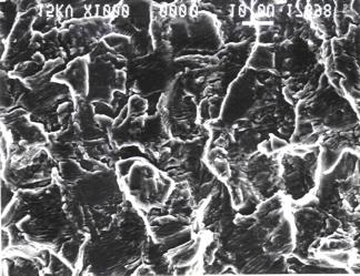
10 intensity factor range was predicted from 5.5 to 11 MPa m, whereas graphical data showed a range from 4 to 13 MPa m. Therefore, the predicted results show very good agreement for both high-humidity and elevated temperature tests. All the data analyzed were high humidity environment only. A two-parameter analysis of variance analysis was performed on the crack growth rate data and parameters of crack growth rate equation (C and m) were analyzed in (15) showing insignificant variations. Fractography Stage I fatigue is normally observed on high cycle - low stress fractures and is frequently absent in low cycle - high stress fatigue (Figure 6) where fracture topography contained mainly striations. The crack follows crystallographic planes but changes direction at discontinuities such as grain boundaries and other particles for Stage I. A typical Stage I fracture is shown in Fig. 15, showing the crack path through the crystallographic planes. The fracture topography contained such features as facets often resembling cleavage where striations do not occur. Figure 15 shows the Stage I behavior observed at 345ºC, implying that these features were common, more pronounced for lower temperature tests. In lack of fracture surfaces from other tests, this study cannot be substantiated further for high humidity tests. However, since Figs. 8 and 12 show crack growth in both Stages I and II, respectively, implying this phenomenon applicable for the tests in room temperature tests in Ti-6Al-4V and Ti-10V-2Fe-3Al. The fracture features shown in Figure 16 (a-d) show transgranular fracture, which is influenced by the magnitude of the alternating stress than by mean stress or microstructure. Stage II fracture surface topography contained such features as striations in Fig. 16 (a-d) ranging from 175 to 345ºC. A variation in stress, temperature, microstructure, frequency and environment can change the orientation of the plane of fracture and alter the direction of striation alignment. These features are observed for all the tests as the alignment of striation planes were different for each case. These alignments, Fig. 16 (a-d), are due to the alignment of α β planes in the microstructure and have not been investigated in this study. Fatigue crack growth process is a very complex interactive phenomenon among material, test, environment and other parameters. Therefore, accurate prediction of FCGR is a challenge. Higher 10
11 temperature and aggressive environment may reduce greatly the crack growth resistance of a material. Cyclic cleavage results in an aggressive environment, whereas secondary cracks and voids form as the temperature increased. Secondary cracks often reduce the state of stress at the tip of a dominating and advancing crack offering crack growth resistance as the test temperature increased. However, there are competition mechanisms among secondary cracks, secondary cracks interacting with the primary crack, and these processes interacting with the material properties at high temperature is very difficult to interpret and quantify. Some voids were observed at 290 and 345ºC as shown in the fractographs Fig. 17 which may provide linking media for the advancing crack. These voids appeared to have been occurred at the boundaries between α platelets in the β indicative of triple point effect aided by a mismatch in ductility, localized slip promoting grain boundary sliding, and/or temperature effects (creep). Whether or not the voids were temperature effects is beyond the scope of this paper. Secondary cracks documented in this paper are shown in Fig 18 (a-b). In the Stage II of the fatigue crack growth region. In that area fine fracture features were seen compared to the early stages of crack growth process where fracture surface features were very rough showing cleavage, crack path changes and crack growth rate interacting with microstructure. Room temperature crack growth process was dictated by the nature of the α β grain, and distribution of alpha platelets in beta grain, in which cyclic cleavage was more deleterious and increased FCR rates. For higher temperature tests (at 345ºC) cavity formed that may indicate a temperature effect. At some point towards the end of Stage II, in Stage III, dimples were observed and fracture was by intergranular mode as shown in Fig. 19. These features were similar to that reported in (1-3, 10). 11
12 Conclusion The fatigue crack growth rates were a function of test parameters used under lab-air, high humidity and elevated temperature environments. Low frequency (1-2 Hz), high stress ratio (R=0.7) tests accelerated the fatigue crack growth rates from 4 to 6 times than high frequency (10 Hz), low stress ratio tests (R=0.05). Each combination of test parameters (stress ratio, environment, and frequency) showed a distinct trend in crack growth rate behavior. However, transition mechanisms in both alloys were a function of environment in which tests were performed. High humidity and elevated temperature reduced the stress intensity range where Stage I transitioned to Stage II. This was also influenced by stress ratio. At higher stress ratio, R=0.7, the transition phenomenon diminished in high humidity environment for both materials. Cyclic plastic zone size calculated empirically was found to predict transitional stress intensity factor satisfactorily for a number of aluminum (2XXX, 6XXX and 7XXX series alloys) and titanium alloys (Ti-6Al-4V and Ti-10V-2Fe-3Al). Tests conducted at elevated temperatures showed bilinear slopes in the crack growth rates showing distinct Stage I and II, respectively. Complex interactions of environment, microstructure, and test parameters were not as significant at lower temperatures and stress ratios. However, more secondary cracks and cavities formed at 20 Hz at or above 290ºC and had a mixed effect on fatigue crack growth rates as secondary cracks may have reduced the stress intensity at the crack tip of a dominating crack and voids may have accelerated the growth of main dominating crack, needs to be investigated further. 12
13 References 1. J.A. Hall, Int. J. Fatigue, 19, 1, 1997, pp. S23-S J.E. Petit, W. Berata, and B. Bouchet, Scripta Metall. 26, pp G.C. Salivar, and J.E. Heive, Eng. Fract. Mech. 32, 5, 1989, pp G.C. Salivar, and F.K. Haake Eng. Fract. Mech. 37, 3, pp L.S. Vesier, and S.D. Antolovitch, Eng. Fract. Mech. 37, 4, 1990, pp M.D. Raizenne, AGARD SMP SC-33, Engine disk test programme fatigue crack growth rate data and modeling cases for Ti-6Al-4V, IMI 685 and Ti-17. National Research Council of Canada, LTR-ST-1785, Nov A. Zeghloul, and J. Petit, Fat. Fract. Engeg. Mater. Struct. 8, 4, 1985, pp T. Ogawa, Y. Hayashi, K. Tokaji, and M. Hirose, Fatigue crack growth of Ti-6Al-4V at elevated temperatures, Japanese Society of Materials Science. 9. G.R. Yoder, L.A. Cooley and T.W.Crooker, Metall. Trans. 11A, 1979, pp D. Eylon, J.A. Hall, Metall. Trans. 8A, 1977, pp R.J.H. Wanhill, R. Galatolo, and C.E.W. Looije, Int. J. Fatigue, 11, 6, 1989, pp B.A. Cowles, Int. J. Fracture, 1996, pp N. Ramchandran, N. Arakere, and T. Goswami, High Temp. Mater. Processes, 19, 5, 2000, pp R.O. Ritchie, Technical Report, Crack growth monitoring: some considerationson the electrical potential method Dept. Metall. Mater. Sc., University of Cambridge, N. Arakere, J. Krohn, T. Goswami and N. Ramchandran, High temperature fatigue crack growth behavior of Ti-6Al-4V, in print, High Temperature Materials and Processes, T. Goswami, Long crack transition mechanisms in Ti-6Al-4V alloy, submitted to Materials Science and Engineering, A. K. Vasudevan, K. Sadananda, and G. Glinka, Critical parameters for fatigue damage, I. J. Fatigue, in Print, T. Goswami and G. E. Gentry, Jr. Unpublished work at Cessna Aircraft Company,
14 Table 1. Parameters of solution treated and over-aged condition for Ti-6Al-4V Solution treat 960 C Water quench Room temperature Overage 700ºC, for 2 hours, air cool Table 2. Mechanical properties of Titanium alloys. Temperature ºC Yield strength Young Modulus % elongation MPa GPa Ti-6Al-4V Room Ti-10V-2Fe-3Alª Room 1073* - 6 Note: a, The material met the minimum properties required by specification AMS *, Average of three tests. 14
15 da/dn Stage II Stage I K T Stress intensity factor range Fig. 1. Schematic representation of Stage I and II crack growth behaviors in titanium alloys. 15
16 Fig. 2. T-L orientation of M-T specimens from the forged bar. 16
17 Fig. 3. Schematic view of disk forging and specimen lay-out. 17

. STOA condition. 18")
18 50 µm Fig. 4 (a). Microstructure of Ti-6Al-4V in STOA condition. 50 µm 50 µm Fig. 4 (b). Microstructure of Ti-6Al-4V in STOA condition. 18

19 50 µm Fig. 5. Microstructure of Ti-10V-2Fe-3Al. Note: This figure may not stay in the final submission as I only have digital image.50 µm 19
20 Strain Fig. 6. Strain accumulation in Ti-6Al-4V alloy at room temperature, 175, 230 and 290 C. 20
21 0.06 Crack length (m) R=0.05 R=0.4 R=0.4 R=0.7 R=0.7 R=0.05 R=0.7 R=0.7 R=0.7 R=0.05 R=0.05 R= E E E+07 Cycles Fig. 7. Crack length versus number of cycles for Ti-6Al-4V high humidity tests. 21
22 1.00E E-07 da/dn (m/cycle) 1.00E E E Delta K (MPa m^1/2) R=0.05 R=0.4 R=0.4 R=0.7 R=0.7 R=0.05 R=0.7 R=0.7 R=0.7 R=0.05 R=0.05 R=0.05 Fig. 8. Crack propagation behavior of Ti-6Al-4V in high humidity environment. 22
23 Fig. 9. Crack length versus number of cycles of Ti-6Al-4V at elevated temperature. 23
24 Fig. 10. Elevated temperature fatigue crack propagation behavior in Ti-6Al-4V alloy. 24
25 Crack length (m) Cycles Lab-air, R=0.3,10 Hz Lab-air, R=0.05, 10 Hz Hi-humidity, R=0.7, 10 Hz Hi-humidity, R=0.05, 2 Hz Lab-air, R=0.3, 10 Hz Lab-air, R=0.7, 10 Hz Hi-humidity, R=0.3, 5 Hz Hi-humidity, R=0.7, 1 Hz Lab-air, R=0.05, 10 Hz Lab-air, R=0.7, 10 Hz Hi-humidity, R=0.05, 5 Hz Lab-air, R=0.3, 10 Hz Fig. 11. Crack length versus number of cycles for Ti-10V-2Fe-3Al alloy. 25
26 1.00E E-06 da/dn (m/cycle) 1.00E E E Delta K (Mpam^1/2) Lab-air, R=0.3,10 Hz Lab-air, R=0.05, 10 Hz Hi-Humidity, R=0.7, 10 Hz Hi-humidity, R=0.05, 2 Hz Lab-air, R=0.3, 10 Hz Lab-air, R=0.7, 10 Hz Hi-humidity, R=0.3, 5 Hz Hi-humidity, R=0.7, 1 Hz Lab-air, R=0.05, 10 Hz Lab-air, R=0.7, 10 Hz Hi-humidity, R=0.05, 5 Hz Lab-air, R=0.3, 10 Hz Fig. 12. Crack propagation behavior of Ti-10V-2Fe-3Al under different test parameters. 26
.")
27 Crack Growth Direction Pits formed on the main crack path Secondary Pits and cracks Fig. 13. Pitting in high humidity environment and crack linking through the pits (X20). 27
28 1.00E E-05 da/dn (m/cycle) 1.00E E E E R=0.05 R=0.05 R=0.05 Delta K R=0.7 R=0.7 R=0.7 R=0.05 Fig. 14. Fatigue crack propagation behavior of aluminum alloy 7075-T

29 Fig. 15. Fractographic features of Stage I crack propagation. 5 µm 29
 230 C")
30 (a) 175 C (b) 230 C 30

 at various")
31 (c) 290 C (d) 290 C Fig. 16. Fractographic features of Stage II crack propagation (striations) at various temperatures. 31

32 Fig. 17. Voiding in Ti-6Al-4V at 345 C. 32


33 (a) 290 C (b) 345 C Fig. 18. Secondary cracking at 290 and 345 C. 33

34 Fig. 19. Intergranular fracture and dimples on the fracture surface indicating overloading failure at 345 C. 34
Prediction of fatigue crack propagation in aluminum alloy with local yield strength gradient at the crack path
 Proceedings of 14 th International Conference on Mesomechanics, Budapest, Hungary, Sept. 25-28. 2012 Prediction of fatigue crack propagation in aluminum alloy with local yield strength gradient at the
ACCELERATED THRESHOLD FATIGUE CRACK GROWTH EFFECT POWDER METALLURGY ALUMINUM ALLOY
 ACCELERATED THRESHOLD FATIGUE CRACK GROWTH EFFECT POWDER METALLURGY ALUMINUM ALLOY R. S. Piascik * and J. A. Newman Fatigue crack growth (FCG) research conducted in the near threshold regime has identified
Fracture. Brittle vs. Ductile Fracture Ductile materials more plastic deformation and energy absorption (toughness) before fracture.
 before fracture.") 1- Fracture Fracture: Separation of a body into pieces due to stress, at temperatures below the melting point. Steps in fracture: 1-Crack formation 2-Crack propagation There are two modes of fracture depending
1- Fracture Fracture: Separation of a body into pieces due to stress, at temperatures below the melting point. Steps in fracture: 1-Crack formation 2-Crack propagation There are two modes of fracture depending
EFFECT OF SHOT PEENING ON FATIGUE PERFORMANCE OF TWO TITANIUM ALLOYS. H. Bae, B. Flinn, M. Ramulu, G. Weber* and H. Diep*
 EFFECT OF SHOT PEENING ON FATIGUE PERFORMANCE OF TWO TITANIUM ALLOYS ABSTRACT H. Bae, B. Flinn, M. Ramulu, G. Weber* and H. Diep* University of Washington, Seattle WA, USA * The Boeing Company, Seattle
1) Fracture, ductile and brittle fracture 2) Fracture mechanics
 Fracture, ductile and brittle fracture 2) Fracture mechanics") Module-08 Failure 1) Fracture, ductile and brittle fracture 2) Fracture mechanics Contents 3) Impact fracture, ductile-to-brittle transition 4) Fatigue, crack initiation and propagation, crack propagation
Module-08 Failure 1) Fracture, ductile and brittle fracture 2) Fracture mechanics Contents 3) Impact fracture, ductile-to-brittle transition 4) Fatigue, crack initiation and propagation, crack propagation
Creep failure Strain-time curve Effect of temperature and applied stress Factors reducing creep rate High-temperature alloys
 Fatigue and Creep of Materials Prof. A.K.M.B. Rashid Department of MME BUET, Dhaka Fatigue failure Laboratory fatigue test The S-N Ncurve Fractography of fractured surface Factors improving fatigue life
ONLINE FATIGUE CRACK GROWTH MONITORING WITH CLIP GAUGE AND DIRECT CURRENT POTENTIAL DROP
 ONLINE FATIGUE CRACK GROWTH MONITORING WITH CLIP GAUGE AND DIRECT CURRENT POTENTIAL DROP S. De Tender, N. Micone and W. De Waele Ghent University, Laboratory Soete, Belgium Abstract: Fatigue is a well-known
Fatigue of metals. Subjects of interest
 Fatigue of metals Chapter 12 Subjects of interest Objectives / Introduction Stress cycles The S-N curve Cyclic stress-strain curve Low cycle fatigue Structural features of fatigue Fatigue crack propagation
Types of Fatigue. Crack Initiation and Propagation. Variability in Fatigue Data. Outline
 Types of Fatigue Outline Fatigue - Review Fatigue crack initiation and propagation Fatigue fracture mechanics Fatigue fractography Crack propagation rate Example Factors affecting fatigue - Design factors
Structures should be designed in such a way that they do not fail during their expected / predicted safe-life
 Structures Any structure is built for a particular purpose Aircraft, Ship, Bus, Train Oil Platforms Bridgesand Buildings Towers for Wind energy, Electricaltransmission etc. Structures and Materials Structuresare
Chapter Outline: Failure
 Chapter Outline: Failure How do Materials Break? Ductile vs. brittle fracture Principles of fracture mechanics Stress concentration Impact fracture testing Fatigue (cyclic stresses) Cyclic stresses, the
A.W. GODFREY and J.W. MARTIN. Oxford University Department of Materials Parks Road OXFORD OX1 3PH, UK. Abstract
 THE EFFECT OF DIRECTIONAL RECRYSTALLIZATION ON THE LCF CHARACTERISTICS OF PM NICKEL-BASED SUPERALLOY APK-6 A.W. GODFREY and J.W. MARTIN Oxford University Department of Materials Parks Road OXFORD OX1 3PH,
HYDROGEN EMBRITTLEMENT AND LOW TEMPERATURE EFFECTS ON CARBON STEELS
 HYDROGEN EMBRITTLEMENT AND LOW TEMPERATURE EFFECTS ON CARBON STEELS LAURA VERGANI Politecnico di Milano, Department of Mechanical Engineering, Milano, Italy CHIARA COLOMBO Politecnico di Milano, Department
CREEP AND FATIGUE CRACK GROWTH IN SEVERAL CAST SUPERALLOYS
 CREEP AND FATIGUE CRACK GROWTH IN SEVERAL CAST SUPERALLOYS P. Shahinian and K. Sadananda Material Science & Technology Division Naval Research Laboratory Washington, DC 20375 Summary Crack growth behavior
Duplex Aging of Ti-15V-3Cr-3Sn-3Al Alloy
 The 2012 World Congress on Advances in Civil, Environmental, and Materials Research (ACEM 12) Seoul, Korea, August 26-30, 2012 Duplex Aging of Ti-15V-3Cr-3Sn-3Al Alloy Ying-Kai Chou 1), *Leu-Wen Tsay 2)
III Fatigue Models. 1. Will a crack nucleate? 2. Will it grow? 3. How fast will it grow?
 III Fatigue Models 1. Will a crack nucleate? 2. Will it grow? 3. How fast will it grow? Outline Sources of knowledge Modeling Crack nucleation Non propagating cracks Crack growth AM 11/03 2 Source of knowledge
Fatigue Crack Paths in Ferritic-Perlitic Ductile Cast Irons
 Fatigue Crack Paths in Ferritic-Perlitic Ductile Cast Irons F. Iacoviello and V. Di Cocco Università di Cassino, Di.M.S.A.T., via G. Di Biasio 43, 03043 Cassino (FR) ITALY, iacoviello@unicas.it ABSTRACT.
Electronics materials - Stress and its effect on materials
 Electronics materials - Stress and its effect on materials Introduction You will have already seen in Mechanical properties of metals that stress on materials results in strain first elastic strain and
EFFECT OF MEAN STRESS ON SHORT CRACK GROWTH IN FATIGUED 316L STAINLESS STEEL
 EFFECT OF MEAN STRESS ON SHORT CRACK GROWTH IN FATIGUED 316L STAINLESS STEEL Karel OBRTLÍK Jiří MAN Jaroslav POLÁK Institute of Physics of Materials, Academy of Sciences of the Czech Republic Žižkova 22,
Technologies for Process Design of Titanium Alloy Forging for Aircraft Parts
 Technologies for Process Design of Titanium Alloy Forging for Aircraft Parts Takashi CHODA *1, Dr. Hideto OYAMA *2, Shogo MURAKAMI *3 *1 Titanium Research & Development Section, Titanium Div., Iron & Steel
Texture and properties - II
 Texture and properties - II Texture and Hall-Petch strength The Hall-Petch equation 0 k d - ½ where, 0 = k = d = lattice frictional stress locking parameter average grain size modifies for textured polycrystals
High frequency fatigue crack propagation behavior of a nickel-base turbine disk alloy
 International Journal of Fatigue 21 (1999) 725 731 www.elsevier.com/locate/ijfatigue High frequency fatigue crack propagation behavior of a nickel-base turbine disk alloy S.A. Padula II a, A. Shyam a,
FATIGUE CRACK GROWTH OF TITANIUM ROTOR ALLOYS IN VACUUM AND AIR
 FATIGUE CRACK GROWTH OF TITANIUM ROTOR ALLOYS IN VACUUM AND AIR R. C. McClung Southwest Research Institute P. O. Drawer 28510 San Antonio, TX 78228-0510 B. H. Lawless GE Aircraft Engines One Neumann Way
Thermomechanical fatigue crack growth in a cast polycrystalline superalloy
 MATEC Web of Conferences 4, 94 (24) DOI:.5/matecconf/24494 c Owned by the authors, published by EDP Sciences, 24 Thermomechanical fatigue crack growth in a cast polycrystalline superalloy Johan J. Moverare,2,a,
HIGH CYCLE FATIGUE OF AN ORTHORHOMBIC TI-22AL- 25NB INTERMETALLIC ALLOY
 HIGH CYCLE FATIGUE OF AN ORTHORHOMBIC TI-22AL- 25NB INTERMETALLIC ALLOY Abstract S.Q.Li, Y.J.Cheng, J.W.Zhang and X.B.Liang Central Iron & Steel Research Institute (CISRI) No.76 Xueyuan Nanlu, Beijing
EFFECT OF LOAD ASYMMETRY AND MICROSTRUCTURE ORIENTATION ON FATIGUE CRACK GROWTH IN STABLE AND THRESHOLD REGIONS IN AN AIRCRAFT AL 2124-T851 ALLOY
 EFFECT OF LOAD ASYMMETRY AND MICROSTRUCTURE ORIENTATION ON FATIGUE CRACK GROWTH IN STABLE AND THRESHOLD REGIONS IN AN AIRCRAFT AL 2124-T851 ALLOY Ivo ČERNÝ SVÚM a.s., Podnikatelská 565, 19011 Praha 9,
Failure and Fracture. Failure and Fracture. Outline. Design Strength and Safety Factors. where N is the.
 Failure and Fracture Outline failure of engineering materials is an undesirable occurrence!! can lead to loss of human life economic losses prevention is through good design and materials selection Failure
Fatigue Overview. F. V. Lawrence FCP 1. Single primary slip system
 Fatigue Overview S Single primary slip system F. V. Lawrence S FCP 1 Fatigue Overview! History of Fatigue! Fatigue Overview! The Process of Fatigue FCP 2 Fatigue-prone Machine FCP 3 Welded Ship - 2 sink
INFLUENCE OF ENVIRONMENT, LOADING FREQUENCY AND TEMPERATURE ON FATIGUE CRACK GROWTH MECHANISMS IN TITANIUM LAMELLAR MICROSTRUCTURES
 INFLUENCE OF ENVIRONMENT, LOADING FREQUENCY AND TEMPERATURE ON FATIGUE CRACK GROWTH MECHANISMS IN TITANIUM LAMELLAR MICROSTRUCTURES C. Sarrazin-Baudoux 1, F. Sansoz 2, and H. Ghonem 3 1 CNRS, Ecole Nationale
Follow this and additional works at: Part of the Mechanical Engineering Commons
 Worcester Polytechnic Institute Digital WPI Mechanical Engineering Faculty Publications Department of Mechanical Engineering 1-1-2012 Effects of Processing Residual Stresses on Fatigue Crack Growth Behavior
Effect of constituent-particles distribution on mechanical behavior of an AlMgSi alloy
 IOP Conference Series: Materials Science and Engineering OPEN ACCESS Effect of constituent-particles distribution on mechanical behavior of an AlMgSi alloy Recent citations - Fatigue crack growth in an
Stress cycles: Dr.Haydar Al-Ethari
 Dr.Haydar Al-Ethari Lecture #17/ Fatigue in metals: Fatigue is a degradation of mechanical properties leading to failure of a material or a component under cyclic loading. (This definition excludes the
Influence of hydrogen environment on fatigue crack growth in forged Ti-6Al-4V: fractographic
 Home Search Collections Journals About Contact us My IOPscience Influence of hydrogen environment on fatigue crack growth in forged Ti-6Al-4V: fractographic analysis This content has been downloaded from
Thin Products < 75 mm 7055-T7751. Strength (MPa) 500. Thick Products mm Year First Used in Aircraft
 500. Thick Products mm Year First Used in Aircraft") Strength and (Extrinsic) Corrosion Resistance Improvements in New 7XXX-Series Alloys - Relative to 7075-T651 All Alloys Still Need Corrosion Protection Schemes 700 650 600 Corrosion Resistance Low Medium
Strength and (Extrinsic) Corrosion Resistance Improvements in New 7XXX-Series Alloys - Relative to 7075-T651 All Alloys Still Need Corrosion Protection Schemes 700 650 600 Corrosion Resistance Low Medium
International Journal of Fatigue
 International Journal of Fatigue 31 (2009) 1137 1143 Contents lists available at ScienceDirect International Journal of Fatigue journal homepage: www.elsevier.com/locate/ijfatigue Fatigue crack propagation
Fatigue Crack Growth Mechanisms in a Forged IN 718 Nickel-Based Superalloy. C. Mercer and W. 0. Soboyejo
 Fatigue Crack Growth Mechanisms in a Forged IN 718 Nickel-Based Superalloy C. Mercer and W. 0. Soboyejo Department of Materials Science and Engineering, The Ohio State University, 2041 College Road, Columbus,
Subject Index. STP 1207-EB/Dec. 1994
 STP 1207-EB/Dec. 1994 Subject Index A Aircraft transparency, crack propagation prediction, 766 AlzO3 ceramics, impact testing, 793 Aluminum alloys stable growing crack, 48 tungsten inert gas welded, 339
GENERATING FATIGUE CRACK GROWTH THRESHOLDS WITH CONSTANT AMPLITUDE LOADS
 GENERATING FATIGUE CRACK GROWTH THRESHOLDS WITH CONSTANT AMPLITUDE LOADS Scott C. Forth *, James C. Newman, Jr. + and Royce G. Forman The fatigue crack growth threshold, defining crack growth as either
Trends and Issues - Titanium Alloy use in Gas Turbines Professor Dave Rugg
 Trends and Issues - Titanium Alloy use in Gas Turbines Professor Dave Rugg Corporate Specialist Compressor and Nuclear Applications Royal Society Industrial Fellow Rolls-Royce plc 2010 The information
Fatigue de-bond growth in adhesively bonded single lap joints
 Sādhanā Vol. 37, Part 1, February 2012, pp. 79 88. c Indian Academy of Sciences Fatigue de-bond growth in adhesively bonded single lap joints P K SAHOO 1,, B DATTAGURU 2, C M MANJUNATHA 1 and CRLMURTHY
FATIGUE BEHAVIOR AND LIFE PREDICTION OF WELDED TITANIUM ALLOY JOINTS
 26 TH INTERNATIONAL CONGRESS OF THE AERONAUTICAL SCIENCES FATIGUE BEHAVIOR AND LIFE PREDICTION OF WELDED TITANIUM ALLOY JOINTS Jianzhong LIU, Lifa WANG and Xue-Ren WU Beijing Institute of Aeronautical
Index. Atmosphere Effect on fatigue processes, 49, 200 Auger spectroscopy, 51 A533-B steel Mode II fracture, 235, 242 B
 STP600-EB/Jun. 1976 Index Abrasion Due to crack closure, 228 On Mode II fractures, 240 AgaMg-AgMg alloys, 160, 166 AISI 1025 steel Hydrogen attack, 88 Microstructure of, 91 Tensile properties, 90 AISI
Corrosion-Fatigue Cracking in HY-80 and HY-130 Steels
 Naval Research Laboratory Washington, DC 20375-5320 NRL/MR/6355--15-9584 Corrosion-Fatigue Cracking in HY-80 and HY-130 Steels P.S. Pao R.L. Holtz Multifunctional Materials Branch Materials Science and
Notch fatigue resistance of shot peened high-strength aluminium alloys: The role of residual stress relaxation
 UNIVERSITÀ DI PISA Notch fatigue resistance of shot peened high-strength aluminium alloys: 1, V. Fontanari 1, C. Santus 2 1 Department of Materials Engineering and Industrial Technologies, University of
Larry Mueller, Leslie Suffredini, Dustin Bush Alcoa Wheel and Forged Products Division Cleveland, Ohio
 Alcoa Green Letter Volume I Alcoa 7085 Die Forgings 7 th Generation Structural Solutions 3 rd Edition August, 2006 (Supersedes the January, 2005 2 nd edition) Larry Mueller, Leslie Suffredini, Dustin Bush
Surface Flaw Effect on LCF Life of a Ni-based Superalloy under Shot Peen Conditions ISABE Ross Miller Honeywell Aerospace Phoenix, AZ
 Surface Flaw Effect on LCF Life of a Ni-based Superalloy under Shot Peen Conditions ISABE-2015-20239 Ross Miller Honeywell Aerospace Phoenix, AZ Abstract Residual stresses are known to influence the fatigue
Fractography: The Way Things Fracture
 Fractography: The Way Things Fracture S.K. Bhaumik Materials Science Division Council of Scientific & Industrial Research (CSIR) Bangalore 560 017 Outline Introduction Classification of fracture Fracture
Effect of Occasional Shear Loading on Fatigue Crack Growth in 7075 Aluminum Alloy M. Makizaki 1, a, H. Matsunaga 2, 4, b, K. Yanase 3, 4, c 3, 4, d
 Materials Science Forum Online: 213-3-11 ISSN: 1662-9752, Vol. 75, pp 264-267 doi:1.428/www.scientific.net/msf.75.264 213 Trans Tech Publications, Switzerland Effect of Occasional Shear Loading on Fatigue
Statistic characteristics of fatigue properties in magnesium alloy
 Available online at www.sciencedirect.com Procedia Engineering 10 (2011) 1232 1237 ICM11 Statistic characteristics of fatigue properties in magnesium alloy S. Mohd a,c, *, Y. Otsuka b, Y. Miyashita b,
Fatigue Crack Growth Analysis of Structural Components - the UniGrow Two-Parameter Driving Force Model
 Fatigue Crack Growth Analysis of Structural Components - the UniGrow Two-Parameter Driving Force Model S. Mikheevskiy 1, G. Glinka 1 and D. Algera 2 1 University of Waterloo, Department of Mechanical Engineering,
Evaluation of uncertainty of crack propagation models Gabriel Tuyishimire
 DEGREE PROJECT FOR MASTER OF SCIENCE WITH SPECIALIZATION IN MANUFACTURING DEPARTMENT OF ENGINEERING SCIENCE UNIVERSITY WEST Evaluation of uncertainty of crack propagation models Gabriel Tuyishimire Abstract
Failure characterisation of Ti6Al4V gas turbine compressor blades
 Computational Methods and Experiments in Materials Characterisation III 383 Failure characterisation of Ti6Al4V gas turbine compressor blades A. Kermanpur 1, H. Sepehri Amin 1, S. Ziaei Rad 2, N. Nourbakhshnia
The Effect of Microstructure on Mechanical Properties of Forged 6061 Aluminum Alloy
 Proceedings of the 9 th International Conference on Aluminium Alloys (2004) Edited by J.F. Nie, A.J. Morton and B.C. Muddle Institute of Materials Engineering Australasia Ltd 1382 The Effect of Microstructure
EFFECT OF POST WELD HEAT TREATMENTS ON THE ELEVATED TEMPERATURE MECHANICAL PROPERTIES OF Ti6Al4V FRICTION WELDS
 EFFECT OF POST WELD HEAT TREATMENTS ON THE ELEVATED TEMPERATURE MECHANICAL PROPERTIES OF Ti6Al4V FRICTION WELDS RAHUL 1#, K. V. RAJULAPATI 1, G. M. REDDY 2, T. MOHANDAS 3, K. B. S. RAO 4 1 School of Engineering
EFFECT OF LOCAL PLASTIC STRETCH OM TOTAL FATIGUE LIFE EVALUATION
 EFFECT OF LOCAL PLASTIC STRETCH OM TOTAL FATIGUE LIFE EVALUATION Abstract G. S. Wang Aeronautics Division, The Swedish Defence Research Agency SE-17290 Stockholm, Sweden wgs@foi.se This paper shows that
CHARACTERIZATION OF TITANIUM ALLOYS FOR CRYOGENIC APPLICATIONS
 CHARACTERIZATION OF TITANIUM ALLOYS FOR CRYOGENIC APPLICATIONS M. Reytier, F. Kircher, B. Levesy CEA Saclay, DSM / DAPNIA / STCM Gif sur Yvette, 91191, France ABSTRACT Titanium alloys are employed in the
Chapter Outline: Failure
 Chapter Outline: Failure How do Materials Break? Ductile vs. brittle fracture Principles of fracture mechanics Stress concentration Impact fracture testing Fatigue (cyclic stresses) Cyclic stresses, the
Chapter 2 Metallurgy and Microstructure
 Chapter 2 Metallurgy and Microstructure 2.1 The General Metallurgy of Titanium Alloys Unalloyed titanium has two allotropic forms. The low temperature form, a, exists as an hexagonal-close-packed (hcp)
DELAMINATION CRACK GROWTH OF UNIDIRECTIONAL CFRP IN THERMO-MECHANICAL FATIGUE
 Proceedings of International Conference on Materials and Mechanics 97 (Tokyo, July 2-22, 1997), pp.653-658. DELAMINATION CRACK GROWTH OF UNIDIRECTIONAL CFRP IN THERMO-MECHANICAL FATIGUE Y. NAKAI, N. SAKATA,
High-cycle fatigue characteristics of squeezed cast aluminum alloy smooth specimens cut from car wheels
 High Performance Structure and Materials VI 95 High-cycle fatigue characteristics of squeezed cast aluminum alloy smooth specimens cut from car wheels M. Goto 1, N. Teshima 2, S. Z. Han 3, K. Euh 3 & T.
Observations of Corrosion Fatigue Crack Initiation Processes in Metals by Means of AFM
 Materials Science Research International, Special Technical Publication 1, pp.11-16 (21) General Paper Observations of Corrosion Fatigue Crack Initiation Processes in Metals by Means of AFM Yoshikazu NAKAI,
INGE Engineering Materials. Chapter 7: Part 2. Mechanical Failure. INGE Engineering Materials. Failure Analysis
 Chapter 7: Part 2 Mechanical Failure This is just an introduction to failure analysis, a much more complex area of materials engineering. Failure Analysis Fractography: The study of fracture Analysis of
ELEVATED-TEMPERATURE CREEP-FATIGUE CRACK-GROWTH BEHAVIOR OF NICKEL- BASED HAYNES R-41, HAYNES 230 and HASTELLOY X AllOYS
 ELEVATED-TEMPERATURE CREEP-FATIGUE CRACK-GROWTH BEHAVIOR OF NICKEL- BASED HAYNES R-41, HAYNES 230 and HASTELLOY X AllOYS S.Y. Lee 1, P.K. Liaw 1, Y.L. Lu 1, D. Fielden 1, L.M. Pike 2 and D.L. Klarstrom
Fatigue resistance of Al-Cu-Li alloys and conventional 7000 and 2000 alloys: notch and environment effects
 Fatigue resistance of Al-Cu-Li alloys and conventional 7000 and 2000 alloys: notch and environment effects J.-C. Ehrström a, O. Andreau a, b, C. Baudoux b a. Constellium C-TEC, 725 rue Aristide Bergès,
High Temperature Fatigue Crack Growth Rate Studies in Stainless Steel 316L(N) Welds Processed by A-TIG and MP-TIG Welding.
 Welds Processed by A-TIG and MP-TIG Welding.") High Temperature Fatigue Crack Growth Rate Studies in Stainless Steel 316L(N) Welds Processed by A-TIG and MP-TIG Welding. Manuel Thomas 1, Raghu V. Prakash 1*, Ganesh Sundara Raman S 3 and Vasudevan,
High Temperature Fatigue Crack Growth Rate Studies in Stainless Steel 316L(N) Welds Processed by A-TIG and MP-TIG Welding. Manuel Thomas 1, Raghu V. Prakash 1*, Ganesh Sundara Raman S 3 and Vasudevan,
Tensile & Fracture Behavior of Al-Si Cp Metal Matrix Composites
 Tensile & Fracture Behavior of Al-Si Cp Metal Matrix Composites Jushkumar Siddani Department of Mechanical Engineering Anurag Group of Institutions, Hyderabad, Telangana, India Dr. C. Srinvas Department
ENGR 151: Materials of Engineering LECTURE #12-13: DISLOCATIONS AND STRENGTHENING MECHANISMS
 ENGR 151: Materials of Engineering LECTURE #12-13: DISLOCATIONS AND STRENGTHENING MECHANISMS RECOVERY, RECRYSTALLIZATION, AND GRAIN GROWTH Plastically deforming metal at low temperatures affects physical
TENSILE AND CREEP-RUPTURE BEHAVIOR OF TWO ADVANCED OXIDE DISPERSION STRENGTHENED SHEET ALLOYS
 TENSILE AND CREEP-RUPTURE BEHAVIOR OF TWO ADVANCED OXIDE DISPERSION STRENGTHENED SHEET ALLOYS W.H. R.J. Wiegert Henricks Pratt and Whitney Aircraft Group, Commercial Products Division, East Hartford CT
E-BRITE E-BRITE. Technical Data Sheet. Stainless Steel: Superferritic GENERAL PROPERTIES PLANAR SOLID OXIDE FUEL CELLS CHEMICAL COMPOSITION
 E-BRITE Stainless Steel: Superferritic (UNS 44627, ASTM Type XM-27) GENERAL PROPERTIES E-BRITE alloy is a high purity ferritic stainless steel which combines excellent resistance to corrosion and oxidation
Mechanical Properties
 Mechanical Properties Elastic deformation Plastic deformation Fracture Fatigue Environmental crack growth Crack Instabilty ß σ T The critical crack length for given σ a a c = Q 2 K Ic σ a 2 a r ß a Sources
A NON-ISOTHERMAL FATIGUE CRACK GROWTH LAW FOR THE A356-T7 ALUMINUM ALLOY. Evry, France Palaiseau Cedex, France
 A NON-ISOTHERMAL FATIGUE CRACK GROWTH LAW FOR THE A356-T7 ALUMINUM ALLOY E. Merhy 1,,3*, L. Rémy 1, H. Maitournam and L. Augustins 3 1 Centre des Matériaux, Mines Paris ParisTech, UMR CNRS 7633, BP87 F-91003
Influence of Primary and Secondary Crystallographic Orientations on Strengths of Nickel-based Superalloy Single Crystals
 Materials Transactions, Vol. 45, No. 6 (2004) pp. 1824 to 1828 #2004 The Japan Institute of Metals Influence of Primary and Secondary Crystallographic Orientations on Strengths of Nickel-based Superalloy
Introduction to Materials Science, Chapter 8, Failure. Failure. Ship-cyclic loading from waves.
 Failure Ship-cyclic loading from waves. Computer chip-cyclic thermal loading. University of Tennessee, Dept. of Materials Science and Engineering 1 Chapter Outline: Failure How do Materials Break? Ductile
1-6.4 THE CRACK TIP: THE INGLIS EQUATION
 1-6.4 THE CRACK TIP: THE INGLIS EQUATION In our discussions of fracture so far we have assumed that the crack looks much like that shown in Figure 1.26a. The crack separates planes of atoms, is atomically
CH 6: Fatigue Failure Resulting from Variable Loading
 CH 6: Fatigue Failure Resulting from Variable Loading Some machine elements are subjected to statics loads and for such elements, statics failure theories are used to predict failure (yielding or fracture).
Mechanical Properties
 Mechanical Properties Elastic deformation Plastic deformation Fracture Fatigue Environmental crack growth Crack Instabilty ß σ T The critical crack length for given σ a a c = Q 2 K Ic σ a 2 a r ß a Sources
Superplastic Forming Properties of TIMETAL 54M
 Superplastic Forming Properties of TIMETAL 54M October 2010 Yoji Kosaka and Phani Gudipati Henderson Technical Laboratory Titanium Metals Corporation 1 Outline Brief Introduction of TIMETAL 54M (Ti-54M)
LOW CYCLE FATIGUE AND FATIGUE GROWTH BEHAVIORS OF ALLOY IN7 18. J. 2. Xie. Institute of Aeronautical Materials Beijing , P. R. China.
 LOW CYCLE FATIGUE AND FATIGUE CRACK GROWTH BEHAVIORS OF ALLOY IN7 18 J. 2. Xie Institute of Aeronautical Materials Beijing 100095, P. R. China Abstract The low cycle fatigue (LCF) behavior and fatigue
A REVIEW OF PARAMETERS AFFECTING DUCTILE FRACTURE OF ALUMINUM ALLOY
 A REVIEW OF PARAMETERS AFFECTING DUCTILE FRACTURE OF ALUMINUM ALLOY Savan P. Makwana M.E.CAD/CAM, Mechanical Engineering, A.D. Patel Institute of Technology, Gujarat, India ABSTRACT This paper reviews
Tensile/Tension Test Advanced Topics
 CIVE.3110 Engineering Materials Laboratory Fall 2017 Tensile/Tension Test Advanced Topics Tzuyang Yu Associate Professor, Ph.D. Structural Engineering Research Group (SERG) Department of Civil and Environmental
Fatigue. David Roylance Department of Materials Science and Engineering Massachusetts Institute of Technology Cambridge, MA
 Fatigue David Roylance Department of Materials Science and Engineering Massachusetts Institute of Technology Cambridge, MA 02139 May 1, 2001 Introduction The concept of \fatigue" arose several times in
Fractography of Fatigue Cracks in Aluminium Alloy AA7050 Subjected to Interrupted Ageing and Retro-Ageing Heat Treatments
 , March 16-18, 2016, Hong Kong Fractography of Fatigue Cracks in Aluminium Alloy AA7050 Subjected to Interrupted Ageing and Retro-Ageing Heat Treatments André L. M. Carvalho, Juliana P. Martins, Enrico
FATIGUE CRACK PROPAGATION BEHAVIORS OF NEW DEVELOPED ALLVAC 718PLUS TM SUPERALLOY
 Superalloys 2004 Edited by K.A. Green, T.M. Pollock, H. Harada, T.E. Howson, R.C. Reed, J.J. Schirra, and S, Walston TMS (The Minerals, Metals & Materials Society), 2004 FATIGUE CRACK PROPAGATION BEHAVIORS
Available online at ScienceDirect. Procedia Engineering 101 (2015 ) 85 92
 85 92") Available online at www.sciencedirect.com ScienceDirect Procedia Engineering 101 (2015 ) 85 92 3rd International Conference on Material and Component Performance under Variable Amplitude Loading, VAL2015
Available online at www.sciencedirect.com ScienceDirect Procedia Engineering 101 (2015 ) 85 92 3rd International Conference on Material and Component Performance under Variable Amplitude Loading, VAL2015
Creep and High Temperature Failure. Creep and High Temperature Failure. Creep Curve. Outline
 Creep and High Temperature Failure Outline Creep and high temperature failure Creep testing Factors affecting creep Stress rupture life time behaviour Creep mechanisms Example Materials for high creep
Fatigue Crack Growth Study in Polymer Matrix Composites
 Fatigue Crack Growth Study in Polymer Matrix Composites Arunakumara P C 1,P.Dinesh 2 1 Department of Mechanical Engneering, M.S.Ramaiah Institute of Technology, Bangalore-560054 2 Department of Mechanical
FATIGUE CRACK PROPAGATION THROUGH AUSTEMPERED DUCTILE IRON MICROSTRUCTURE
 Materials Engineering, Vol. 17, 2010, No. 3 15 FATIGUE CRACK PROPAGATION THROUGH AUSTEMPERED DUCTILE IRON MICROSTRUCTURE Lukáš Bubenko 1, Radomila Konečná 1, Gianni Nicoletto 2 Received 24 th September
Titanium and titanium alloys. Josef Stráský
 Titanium and titanium alloys Josef Stráský Lecture 3: Technological aspects of Ti alloys Pure Ti metallurgy, properties and applications α+β alloys microstructures, metallurgy, heat treatment Ti-6Al-4V
Damage Tolerance of Alloy 718 Turbine Disc Material
 Damage Tolerance of Alloy 718 Turbine Disc Material M. Chang, P. Au**, T. Terada**, and AK. Koul** * Dept of Mechanical and Aerospace Engineering, Carleton University, Ottawa, Canada ** Structures and
Effect of Notch Diameter on the Fracture Toughness of Al7075 T6 Alloy- An Experimental Approach
 Effect of Diameter on the Fracture Toughness of Al7075 T6 Alloy- An Experimental Approach Basawaraj V. Dharne Faculty of Mechanical Department, M. S. Bidve Engineering College, Latur, Maharashtra, India
THE MECHANICAL PROPERTIES OF STAINLESS STEEL
 THE MECHANICAL PROPERTIES OF STAINLESS STEEL Stainless steel is primarily utilised on account of its corrosion resistance. However, the scope of excellent mechanical properties the within the family of
Fatigue Damage Management Based on Postulated Crack Growth Curve
 E-Journal of Advanced Maintenance Vol.7- (25) 43-49 Japan Society of Maintenology Fatigue Damage Management Masayuki KAMAYA,* and Takao NAKAMURA 2 Institute of Nuclear Safety System, Inc., 64 Sata, Mihama-cho,
EFFECTS OF MECHANICALLY DRILLED PITS ON TENSILE DUCTILITY AND FRACTURE BEHAVIOR OF A STRUCTURAL STEEL
 EFFECTS OF MECHANICALLY DRILLED PITS ON TENSILE DUCTILITY AND FRACTURE BEHAVIOR OF A STRUCTURAL STEEL Somayeh ALIPOUR, Hassan FARHANGI and Changiz DEHGHANIAN School of Metallurgy and Materials Engineering,
The Effect of Crystallographic Texture on the Wrap Bendability in AA5754-O Temper Sheet Alloy
 Proceedings of the 12th International Conference on Aluminium Alloys, September 5-9, 2010, Yokohama, Japan 2010 The Japan Institute of Light Metals pp. 607-612 607 The Effect of Crystallographic Texture
THE EFFECT OF HIGH CYCLE FATIGUE DAMAGE ON TOUGHNESS OF EN8 GRADE STEEL PART II
 Int. J. Mech. Eng. & Rob. Res. 2013 P Talukdar et al., 2013 Research Paper ISSN 2278 0149 www.ijmerr.com Vol. 2, No. 2, April 2013 2013 IJMERR. All Rights Reserved THE EFFECT OF HIGH CYCLE FATIGUE DAMAGE
INFLUENCE OF SHOT PEENING ON THE FATIGUE BEHAVIOR OF TITANIUM ALLOYS
 INFLUENCE OF SHOT PEENING ON THE FATIGUE BEHAVIOR OF TITANIUM ALLOYS L. Wagner* and G. Luetjeringe* *Ruhr-Universitaet Bochum, Federal Republic of Germany * *Technixhe Universitaet Hamburg-Harburg, Federal
The Influence of Heat Treatment on the Structure and Tensile Properties of Cast Titanium Alloy Ti-5111
 The Influence of Heat Treatment on the Structure and Tensile Properties of Cast Titanium Alloy Ti-51 A.C. Robinson 1, E.J. Czyryca 1, and D.A. Koss 2 1 Naval Surface Warfare Center, Carderock Division,
Damage Tolerant Design for a Cast Aluminium Alloy
 Proceedings of the 9 th International Conference on Aluminium Alloys (2004) Edited by J.F. Nie, A.J. Morton and B.C. Muddle Institute of Materials Engineering Australasia Ltd 345 Damage Tolerant Design
Corrosion-Fatigue Cracking in Al 7075 Alloys
 Naval Research Laboratory Washington, DC 20375-5320 NRL/MR/6355--14-9582 Corrosion-Fatigue Cracking in Al 7075 Alloys P.S. Pao R.L. Holtz Multifunctional Materials Branch Materials Science and Technology
Damage Tolerant Design for a Cast Aluminium Alloy
 MATERIALS FORUM VOLUME 28 - Published 2004 Edited by J.F. Nie, A.J. Morton and B.C. Muddle Institute of Materials Engineering Australasia Ltd 345 Damage Tolerant Design for a Cast Aluminium Alloy W.J.