ANALYSIS OF FATIGUE CRACK GROWTH IN SHIP STRUCTURAL DETAILS
|
|
|
- Hortense Garrett
- 6 years ago
- Views:
Transcription
1 POLISH MARITIME RESEARCH 2 (90) 2016 Vol. 23; pp /pomr ANALYSIS OF FATIGUE CRACK GROWTH IN SHIP STRUCTURAL DETAILS Heba W. Leheta Ahmed M. H. Elhewy Helmy A. Younes Naval Architecture and Marine Engineering Department, Faculty of Engineering, Alexandria University ABSTRACT Fatigue failure avoidance is a goal that can be achieved only if the fatigue design is an integral part of the original design program. The purpose of fatigue design is to ensure that the structure has adequate fatigue life. Calculated fatigue life can form the basis for meaningful and efficient inspection programs during fabrication and throughout the life of the ship. The main objective of this paper is to develop an add-on program for the analysis of fatigue crack growth in ship structural details. The developed program will be an add-on script in a pre-existing package. A crack propagation in a tanker side connection is analyzed by using the developed program based on linear elastic fracture mechanics (LEFM) and finite element method (FEM). The basic idea of the developed application is that a finite element model of this side connection will be first analyzed by using ABAQUS and from the results of this analysis the location of the highest stresses will be revealed. At this location, an initial crack will be introduced to the finite element model and from the results of the new crack model the direction of the crack propagation and the values of the stress intensity factors, will be known. By using the calculated direction of propagation a new segment will be added to the crack and then the model is analyzed again. The last step will be repeated until the calculated stress intensity factors reach the critical value. Keywords: Fatigue crack, linear elastic fracture mechanics (LEFM), finite element method (FEM) INTRODUCTION Although a ship may be designed to withstand the ultimate stresses imposed by heavy storm waves, failure could occur due to apparently low stresses generated by the continuously encountered smaller, although significant, ocean swells, as well as impact loads resulting from the routine loading and manoeuvring of a ship. When assuming that a ship has a life of 20 years and operates at sea for 75% of her life time, and knowing that the medium period of wave encounter is approximately equal to 5 seconds, the ship will experience nearly 100 million loading cycles throughout her life. Structural failure of a ship may result in consequences that range from simple leaks to severe loss of lives. The failure consequences are functions of the ship s age, the damaged component, its location, and the maintenance and repair history of the ship [1, 2] In the past, ship structure design often did not incorporate explicitly an analysis of fatigue. However, as stated in the subject-matter literature, the main reasons for interest to studying fatigue cracking is, in the last few years, the introduction of high tensile steels and the development of very large ships (e.g. VLCC, ULCC) which results in increasing the stresses in critical structural details and decreasing its fatigue life. Although the allowable stress methods are used in the design of majority of ship structures, more and more of the new designs incorporate detailed analysis methods. [3,4] Fatigue failure avoidance is a goal that can be achieved only if the fatigue design is an integral part of the original design program. An improper design may lead to an unacceptable catastrophic fatigue failure resulting in loss of life and damage 71
2 to the environment. Non-catastrophic fatigue failures are also unacceptable due to difficulty and cost of repairs as well as the need to increase costly inspection and maintenance intervals. The aim of fatigue design is to ensure that the structure has adequate fatigue life. Calculated fatigue life can also form basis for meaningful and efficient inspection programs during fabrication and throughout the life of the ship [3, 5]. The finite element method is a numerical procedure that can be applied to obtain solutions to a variety of engineering problems e.g. stress analysis, heat transfer, fluid flow, etc. Such problems may be steady, linear, or nonlinear ones. Yet, it was not until 1960 that Clough made the term finite element popular [6]. There are many finite element software packages available in the market however, most of them do not have a built- in function for fatigue analysis. The few that have a built -in function for fatigue analysis can be used to study fatigue crack propagation along a predefined path. For example, ABAQUS ver. 14 software package has either static crack analysis or crack propagation analysis but the crack propagation path must be known before the analysis. The case of predefined path crack analysis may be practical for the analysis of lamination cracks, e.g. in fibre glass composites. However, this feature cannot be used for crack in steel ship structural details where the crack path is unknown. The aim of this paper is to evaluate fatigue analysis by using linear elastic fracture mechanics ( LEFM), and to achieve this aim an add-on program is developed to analyze fatigue crack growth in ship structural details. The program will be an add-on script in ABAQUS software. The application was developed by using python programming language which can be incorporated into ABAQUS to extend its features. The fatigue analysis techniques are presented in the next section, where a summary on cumulative damage approach emphasizing linear cumulative damage approach (Miner s rule) is discussed. A detailed discussion of fracture mechanics especially linear elastic fracture mechanics, LEFM, is presented in Sec. 4. Also crack stages and stress intensity factors are discussed. The application of LEFM for fatigue analysis is given to show fatigue life calculation by using LEFM (Paris law). METHODS FOR FATIGUE ANALYSIS A broad view of the common methods for fatigue analysis is shown in Fig. 1 [7]. Fatigue analysis may be carried out by methods based on fatigue tests (S-N data) and estimation of cumulative damage (Miner rule). Another approach to fatigue analysis is fracture mechanics which is discussed in details in the following section, separately. Predicting fatigue damage for structural components subjected to variable loading conditions is a complex issue. The first, simplest, and most widely used damage model is the linear damage. This rule is often referred to as Miner s rule (1945). However, in many cases the linear rule often leads to non-conservative life predictions. The results from this approach do not take into account the effect of load sequence on the accumulation of damage due to cyclic fatigue loading. Since the introduction of the linear damage rule many different fatigue damage theories have been proposed to improve the accuracy of fatigue life prediction [3, 8, 9]. Ship structure design often did not include explicit treatment of fatigue by means of an analysis. However, with the increasing in using higher strength steels and the increased cyclic stress ranges, fatigue analysis of structures is increasingly required. Although the developed allowable stress methods ( which use S-N curves) are applied in the design of majority of ship structures, more and more of the new designs incorporate detailed analysis methods (which use fracture mechanics) [6]. The material resistance to fatigue failure primarily depends on the characteristics of detail/joint geometry, material chemical composition and mechanical properties, and the service environment. The material resistance is typically determined in laboratory tests by the application of constant amplitude stress cycle on various detail/joint geometries until fatigue failure occurs. By carrying out similar tests for different stress amplitudes a relationship between the stress amplitude, S, and the number of cycles, N, is established. The S-N curves developed for simple details (i.e., stiffener, cut-out, etc.) account for the peak stresses and can be directly used with the member nominal stresses [10]. The application of linear elastic fracture mechanics, LEFM, in estimating the life of the structure assumes that cracks has already initiated in the material. The behaviour of the crack can be predicted under anticipated service loading. The estimated behaviour is used to schedule inspection and maintenance in order to assure that defects do not propagate to a catastrophic size [3]. FRACTURE MECHANICS APPROACH This section provides an introduction to the important Fig. 1 Fatigue Analysis Techniques 72
3 aspects of linear elastic fracture mechanics (LEFM) and shows how it can be used to describe and predict fatigue crack growth rate and fatigue life. It provides a general background for the concepts of fracture mechanics and numerical tools needed for fatigue design involving crack growth and fracture analysis. The basic control factors in fracture mechanics are the stress intensity factor K, the energy release rate G, the crack opening displacement COD, and the J-integral J. These quantities along with their critical or limiting values are the foundation of any fracture analysis [7]. LEFM CONCEPTS Fracture mechanics is used to evaluate the strength of a structure or component in the presence of a crack or flaw. Its application to fatigue involves the crack growth process, covering the range from a detectable crack or flaw to final fracture. One of the common methods used to analyze this process is LEFM. The method is used to determine crack growth in materials under the basic assumption that material conditions are predominantly linear elastic during the fatigue process. For crack growth or fracture conditions that violate this basic assumption, elastic-plastic fracture mechanics approaches are used to describe the fatigue and fracture process. It is necessary to define the basic crack surface displacement modes by which a crack can extend before using LEFM concepts for the crack growth analysis [11]. tip stress intensity factor is an extremely useful parameter to address crack growth behaviour as long as the bulk of the material is elastic and plastic deformation is limited to a small region at the crack tip [12]. In order to illustrate the basic parameters of the fatigue crack growth, Fig. 3 shows a typical plot of crack propagation where it is noticed that: Crack length increases with the increasing number of loading cycles; Crack growth rate most often increases with increasing crack length; Crack growth rate increases with increasing stress level; Crack becomes longer at an increasingly rapid rate; Most of the loading cycles involved in the total life of the component are consumed during the early stages of crack extension [10, 13]. MODES OF CRACK EXTENSION Fig. 2 shows three modes by which a crack can extend. Mode I is the opening (tensile) mode where the crack surfaces move directly apart ; Mode II is the sliding (in-plane shearing) mode where the crack surfaces slide over one another in the direction perpendicular to the leading edge of the crack; Mode III is the tearing (anti-plane shear) mode where the crack surfaces move relative to one another and parallel to the leading edge of the crack. FATIGUE CRACK GROWTH BASED ON LEFM The main goal of the application of fracture mechanics in fatigue analysis is to estimate the total number of cycles for the assumed initial crack a i to reach a final length a f. The crack Fig. 3 Effect of crack length and stress level on crack propagation rate In general, as shown in Fig. 4, Fig. 5 and 6, it has been observed that the fatigue process involves the following stages: 1. Stage I Initiation a. Cyclic slip b. Crack nucleation, c. Short (micro) crack growth, 2. Stage II Stable crack growth a. Long (macro) crack growth, and 3. Stage III unstable crack growth a. Final fracture. FATIGUE ANALYSIS OF SHIP STRUCTURES Fig. 2 Modes of crack extension Fatigue is responsible for a large amount of cracks occurring in welded ship structural details. For many years fatigue - related failure has become a major concern in the maintenance 73
.")


![Note that improved detail design which would cause a reduction of the SCF value for ship structural details, has minimized the effect of increased stress level [4, 14]. 2.](/docs-images/75/72624676/images/4-10.jpg "Tankers operate on trade routes (e.g.")
 in ballast and cargo tanks resulting in a reduction of the fatigue life of ship structural details [4].")
 loading have an adequate fatigue life.")
4 Fig. 4 Phases of fatigue cracking Fig. 5 Different scenarios of fatigue crack growth Fig. 6 Fatigue rate curve da/dn versus K of existing ships and the design of new ships especially after the introduction of high tensile steel ( HTS). Numerous cracks were experienced by relatively new oil carriers constructed of HTS materials. The cracks were discovered when the ships were about 3 to 4 years old without any significant corrosion or wastage [1, 14]. The main factors affecting increased number of fatigue cracks in ships may be summarized as follows: 1. The trend of reducing the ship scantlings based on detailed stress analysis and the increased use of HTS, has resulted in the increase of the general stress level. Note that improved detail design which would cause a reduction of the SCF value for ship structural details, has minimized the effect of increased stress level [4, 14]. 2. Tankers operate on trade routes (e.g., TAPS trade route from California to Alaska) having severe weather for the majority of their operational time, which causes very severe loading with respect to fatigue damage. 3. The presence of corrosion (general, pitting, and grooving) in ballast and cargo tanks resulting in a reduction of the fatigue life of ship structural details [4]. Due to the growing number of fatigue cracks a more direct control of fatigue is needed. The aim of the fatigue control is to ensure that all parts of the hull structure subjected to fatigue (dynamic) loading have an adequate fatigue life. Calculated fatigue lives, calibrated with the relevant fatigue damage data, may give the basis for the structural design (steel selection, scantlings and local details). Furthermore, they can form the basis for efficient inspection programs during fabrication and throughout the service life of the structure. [14] AREAS SUSCEPTIBLE TO FATIGUE DAMAGE Fatigue damages are known to occur more frequently for some ship types and categories of hull structure elements. The fatigue life is in particular related to the magnitude of the dynamic stress level, the corrosiveness of the environment and the magnitude of notch and stress concentration factors of the structural details, which all vary depending on ship type and structure. The importance of possible fatigue damage is related to the number of potential damage points of a considered type for the ship or structure in question and to its consequences. [14] In ship structures a major fraction of the total number of fatigue damages occurs in panel stiffeners on the ship side and bottom and on the boundaries of ballast and cargo tanks [14]. Fig. 7 and 8 show a possible distribution of fatigue cracks in a typical ship structural component. In tankers, cracks occur mostly on the side longitudinals at the connections to transverse bulkheads or transverse webs. Other ship types such as bulk carriers also suffer from fatigue cracks. Where in some bulk carriers, cracks were commonly found in the hard corners of the lower hopper tanks connecting to the 74
![side frames, and the lower stools connecting to the double bottom [1].](/docs-images/75/72624676/images/5-0.jpg "DNV [14] and other classification societies has published some tables showing the critical areas for different ship types.")


 or a propagating crack through a predefined path.")


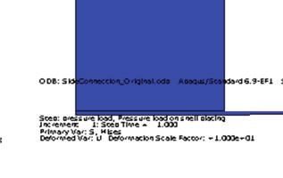
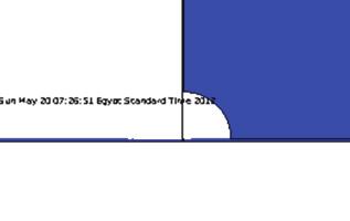
5 side frames, and the lower stools connecting to the double bottom [1]. DNV [14] and other classification societies has published some tables showing the critical areas for different ship types. As an example for tankers Tab. 1 is listed hereunder. Tab.1 Critical details for a tanker Structure member Structural detail Load type Side, bottom and deck plating and longitudinals Transverse girder and stringer structures Longitudinal girders of deck and bottom structure Butt joints, deck openings and attachment to transverse webs, transverse bulkheads, hopper knuckles and intermediate longitudinal girders Bracket toes, girder flange butt joints, curved girder flanges, knuckle of inner bottom and sloped hopper side and other panel knuckles including intersection with transverse girder webs. Single lug slots for panel stiffeners, access and lightening holes Bracket terminations of butting transverse members (girders, stiffeners) Hull girder bending, stiffener lateral pressure load and support deformation Sea pressure load combined with cargo or ballast pressure load Hull girder bending, and bending / deformation of longitudinal girder and considered abutting member PROPOSED PROCEDURES APPLICABLE TO CUT-OUTS A calculation method applied to a cut-out model in a side connection of a crude oil carrier, is proposed. The model encompasses a longitudinal stiffener passing through a side transverse. Due to the cut-out introduced in the side transverse this connection is suspected of fatigue failure [15]. Also, the following assumptions are used for the analysis of the finite element model: Material is isotropic; Linear fracture mechanics applies; the plastic zone in the crack front is minimal. ABAQUS built- in features can only be used to analyze a static crack (i.e. in-site crack) or a propagating crack through a predefined path. The case of crack propagation through a predefined path is practical for the analysis of laminations (i.e. fibre glass reinforced composites). However, in case of fatigue crack propagation through ship structural details the path of the crack is unknown. Hence, because of limitation of this software a special script is developed with the purpose of analyzing a propagating crack without having predefined path. The simplest way to explain this idea is that a static crack will be first analyzed and from the analysis the crack propagation direction is made known and then the crack is propagated in this direction. Another static crack will be analyzed in the new location until the crack is terminated. MODELLING THE ORIGINAL, NON- CRACKED ELEMENT MODEL The original model is analyzed by using the finite element method to indicate the critical point, i.e. the point where maximum stresses occur and where the crack is suspected to start. The modelling technique, meshing and loading of the original model is discussed below. MODELLING THE GEOMETRY The crack analysis can be carried out by using either 2D or 3D models. For each model either shell or solid elements Fig. 7 Distribution of ship s fatigue cracks Fig. 8 Critical structural details 75


![partially through cracks, e.g. penny cracks in shafts [16].](/docs-images/75/72624676/images/6-4.jpg "Fig. 9 and 10 show model dimensions in two")


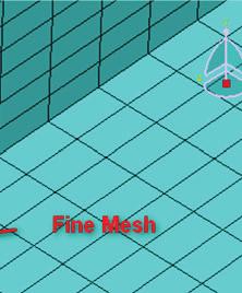
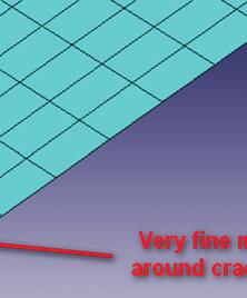
6 Fig. 9 Model dimensions can be used. The modelling by using shell and continuum elements can be applied to analyzing fully through cracks, e.g. a cracked plate. However continuum elements cannot be used for 3D modelling. The solid modelling has the advantage of analyzing both fully through cracks and partially through cracks, e.g. penny cracks in shafts [16]. Fig. 9 and 10 show model dimensions in two views. Since most cracks in the ship structures will be fully through ones, hence the using of shell elements will be much easier than solid elements with no reduction in the quality of the analysis. This also helps reducing the programming used in propagating cracks and reduces the time required for the analysis. The proposed element is that of four nodes, S4, which can be degenerated into a triangle to allow the account of crack tip singularity. The area around the cut-out in the web frame, with estimated high stress concentration, will be meshed by using a finer mesh as shown in Fig. 11 and 12. Fig. 10 Model dimensions After several trials by using both medial axis and advancing front meshing algorithms, the advancing front meshing algorithm was selected for this analysis. The medial axis meshing algorithm is much faster than the advancing front meshing algorithm, especially with the repeated re-meshing. However, due to sensitivity of the mesh around the crack tip, especially in the initiation phase, the mesh has to follow an exact seeding pattern which can only be achieved by using the advancing front meshing technique [17]. BOUNDARY CONDITIONS Some studies were made to show the effect of boundary conditions on the hot-spot stress. The results showed the insensitivity of the fixation boundary conditions on the hotspot stress away from the boundary. However, boundary conditions are based on symmetry, continuity and engineering judgment. The boundary conditions applied to this analysis are shown in Fig.13, where, UX, UY and UZ are the translation Fig. 11 Different mesh sizes Fig. 12 Different mesh sizes 76

 m where the effective stress intensity factor range K eff")
 4 INTRODUCTION OF A NEW CRACK SEGMENT Fig.")


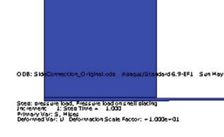
7 in X, Y and Z directions, respectively, and ROTX, ROTX and ROTX are the rotation about X, Y and Z axis, respectively, [15, 18]. as a function of an effective stress intensity factor: da = C ( K eff dn ) m where the effective stress intensity factor range K eff for combined mode -I and- II loadings is expressed by: 1 K eff = ( K I4 + 8 K II4 ) 4 INTRODUCTION OF A NEW CRACK SEGMENT Fig. 13 FEM model boundary conditions APPLIED LOADS To analyze the crack propagation by using fracture mechanics the fatigue loading will be simplified as much as possible. This could be done by choosing a detail placed as close to the ship s neutral axis as possible to eliminate hull girder loads. In addition, the cargo tank will be assumed empty to eliminate internal loads. Hence, for the considered model of oil tanker s side connection, the fatigue loads playing the major role in this analysis, are those resulting from the varying sea water pressure on the outer shell. After the analysis of the initial crack and determining the value of the crack extension angle θˆ, a new crack extension segment with the length da is introduced. The da - length is not an essential value for the analysis, however a smaller da value will lead to better numerical integration for the fatigue life. And of course the smaller the value the more calculation processes are needed and hence the time to complete a full analysis. One major problem that occurs when selecting a relatively large length da is that the meshing becomes impossible sometimes. This is due to the big difference between the seed values of the lines representing the start of the crack, see Fig.14 below. INITIAL CRACK LOCATION OF INITIAL CRACK The welded structure in question will be assumed to have only one initial crack. After the analysis of the non-cracked element model the location of the maximum stresses (von Mises stress) is recorded and will represent the location for the start point of the initial crack. SIZE OF INITIAL CRACK As discussed before, the initial crack length can be estimated by using different methods, and to keep the estimation practical, the crack length is assumed as that of the smallest crack detectable by using X-ray NDT method; this length is equal to 3.81mm. [7] RESULTS OF THE INITIAL CRACK ANALYSIS After the analysis of the initially cracked element model, the values of KI and KII are obtained directly by applying the finite element model. The fatigue crack growth rate has been expressed by Tanaka [20] who used a Paris type equation Fig. 14 Different values of the crack extension da ANALYSIS OF THE CRACKED ELEMENT MODEL AFTER EXTENSION The analysis of the model after each crack extension is continued and all relevant values are stored for each step of the crack extension. The most important parameters are : a, KI, KII, Keff, θˆ.the event of Keff > KC means that the crack will continue to propagate under Paris law. Hence a new crack segment is introduced and analyzed, as stated previously in 6.4. This analysis continues until the effective stress intensity 77
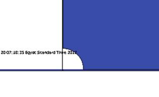
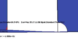
8 factor K eff reaches its maximum value which is equal to the value of the critical stress intensity factor K C. The event of K eff > K C means that the stage II of stable crack growth have ended and Paris law is no more applicable. The crack size a at this stage, can be considered the critical crack size, a c. As discussed before, after reaching this value the crack propagation enters stage III where the crack propagates at very high speed and will not affect the fatigue life calculation. Hence, at this stage the analysis can be ended without any compromise in the calculation of the fatigue life of the model. Another important check which must be programmed is to check that each time a new crack segment is introduced and the end of this crack segment still remains within the domain of the model. Unless this quite simple check is programmed the program may never terminate if the variable load is small and the model is completely cracked without reaching the condition of K eff > K C. FATIGUE LIFE CALCULATION The fatigue life calculation can be accomplished in two stages. First, the number of fatigue load cycles required to propagate the crack from the initial size a i to the final size a f. This can be done by integrating Paris formula, as discussed below. The second step is to estimate the number of fatigue load cycles that occur each year for a ship. This way the calculated number of cycles from the first step can be translated into number of years. upon the analysis being undertaken, this approximation may not be adequate. Finally, the Paris law does not consider the effect of stress ratio and it depends upon the used material. For steels tested at various stress ratios, a family of straight lines parallel to each other is produced. This means that the value of m is the same for all stress ratios but the value of C is specific for a particular stress ratio. FATIGUE LIFE As indicated in Bureau Veritas rules [19] the number of cycles for the expected ship s life Nt can be estimated by using the following equation: where: T is the design life in seconds, L is the length of the ship, α o is the sailing factor which takes into account the time needed for loading/unloading operations, repairs, etc. As a rule, α o may be taken equal to Calculating the number of cycles corresponding to a crack length or final failure, knowing the number of cycles by using crack propagation analysis as stated before, the previous relation could be used accordingly, to estimate the time (e.g. number of years) corresponding to each stage of the crack growth. NUMBER OF CYCLES TO FAILURE At the end of the calculations and after the value of the range of effective stress intensity factor K eff exceeds the value of the critical stress intensity factor K C, the fatigue life, as number of cycles to failure, can be calculated by using numerical integration of Paris law, as discussed in 6.3. Finally, by using the assumptions of number of load cycles per year, the life of the ship can be calculated. Also the following graphs can be plotted: Crack profile; K eq, K I and K II versus crack length a; K eq, K I and K II versus time; Crack length a versus time; RESULTS In the discussed analysis method the step at which crack propagates, da, is held constant all over the analysis. Also the material constants C and m are kept constant. Hence the above mentioned integration can be simplified into a very simple summation as follows: The limitation of the Paris law is that it is only capable of describing data in Stage II (see Fig. 6). If the data exhibits a threshold (Stage I) or an accelerated growth (Stage III) Paris law cannot adequately describe these regions. Depending After the successful running of the developed program shown in the flow chart of Fig. 15, the results of the analysis could be presented as follows: A crack will initiate at the scallop of the cut-out in the web frame due to increased stresses at this area. This crack will start propagating towards the side shell plating due to fatigue loading. The total life of the model was calculated to be 7.8 years. The illustration of the crack propagation during the fatigue life of the model is illustrated in the form of graphs and crack profiles for different stages of the crack propagation. Tab. 2 shows the summary of the different phases. 78


 Crack length Time % a f T (years) % Life Fig. 16 3.81 0% 0 0% Fig. 17 39.81 6% 1.")
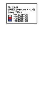
9 the material. CRACK LENGTH VERSUS TIME Fig. 25 shows that the crack starts propagating at a relatively very low rate. As an example, 25% of the fatigue life is consumed to propagate the crack for only 6% of its final length. However the rate increases rapidly after reaching about 50% of the fatigue life. Also, it shows that the last 50% of the crack length is consumed rapidly in less than 7% of the total life. EQUIVALENT STRESS INTENSITY FACTOR VERSUS CRACK LENGTH AND TIME Fig. 26 shows that the equivalent stress intensity factor K eq increases steadily during the crack propagation phase while increases rapidly at the final stages. This shows that the K eq follows Paris law during stage II of the propagation phase. In combination with Fig. 26, Fig. 27 shows that during stage II of the propagation phase, where the K eq follows Paris law, the K eq increases by the increasing of the crack size. However, at the final stages it decreases with the increase of crack size. This shows that the analysis is only valid for the propagation period because the developed programs is only applicable to the area following Paris law and does not include formulas for stage III of the crack propagation. Fig. 15 Flow chart of the developed program Tab. 2 Summary of crack propagation Figure a ( mm ) Crack length Time % a f T (years) % Life Fig % 0 0% Fig % % Fig % % Fig % % Fig % % Fig % % Fig % % Fig % % Fig. 16 Initial crack profile CRACK PROFILE AND STRESS FIELD The stress field shown in Fig. 24 illustrates the distribution of the stresses around the crack tip. The red area in the region indicates where the stress is higher than the yield stress of Fig. 17 Crack profile a=39.81 mm=6% a f t = 1.9Years = 25% Life 79


10 80


 for such parts of the ship, e.g. close-up survey for tankers. 5.")


11 CONCLUSIONS 1. The fatigue durability of ship structural details is achieved not only by careful initial design but also by a proper construction and an effective inspection, maintenance and repair program. 2. FEM is a very cost- effective tool for structural analysis which saves a lot compared to physical model testing. However, FEM cannot substitute physical testing since the results from FEA should be verified by using physical models. However application of FEM reduces the number of physical models to be tested hence also the cost of the analysis. 3. The developed program is used for the fatigue analysis of a side connection of a tanker. It uses basic programming and features of ABAQUS software package. A more complicated and generic programs can be derived by applying the same methodology for the analysis of other models. 4. Crack propagation analysis for ship structural details helps scheduling the inspection programs (locations and period) for such parts of the ship, e.g. close-up survey for tankers. 5. Fatigue analysis of the ship connections and details is very important because designing a ship that would not suffer fatigue, i.e. in the case of K K th, is highly impractical. The lightweight of the ship will be then increased exponentially, reducing her deadweight. In addition, the added material will increase the initial cost of building the ship. 6. All of the above mentioned side effects could be avoided by carefully designing the ship structural details vulnerable to fatigue damage. 7. Immediate repair and docking delay the delivery of cargo and decrease the profit from this ship. 8. The ships that usually encounter fatigue problem are large tankers and bulk carriers. Hence, in the most extreme cases where the cracks are left without inspection or repair, the situation may lead to leakage of oil or hazardous fluids into the sea causing environmental problems. 9. Finally, the most effective way is to conduct an overall fatigue analysis for any new design of tankers or bulk carriers. As a result of such analysis the schedule of inspection of critical details can be determined. In this case, the high initial cost and loss of deadweight can be avoided, moreover the critical parts where fatigue cracks may occur are in advance determined 81
12 before their growing into catastrophic cracks. On the contrary, if fatigue analysis was not conducted, this may lead to cracks in different high - stressed spots. If the cracks are not repaired in a satisfactory manner, they may lead to damage of ship members BIBLIOGRAPHY 1. B. Ayyub, et al. : Risk-informed inspection of marine vessels. Ship Structures Committee, SSC-421, R. Bea: Maintenance of marine structures: A state of the art summary. DTIC Document C. C. Capanoglu: Fatigue Technology Assessment and Strategies for Fatigue Avoidance in Marine Structures. Ship Structure Committee (SSC), T. Xu : Fatigue of ship structural details Technical Development and Problems. Journal of Ship Research, vol. 41, pp , S. Moaveni: Finite element analysis: theory and application with ANSYS. Upper Saddle River, N.J.: Prentice Hall, Y.-L. Lee: Fatigue testing and analysis: theory and practice. Amsterdam; Boston: Elsevier Butterworth-Heinemann, J. Schijve: Fatigue of structures and materials. New York: Springer, International Association of Classification Societies ltd. (IACS) : Standard Wave Data. Recommendation 34, Det Norske Veritas : Fatigue Strength Analysis of Offshore Steel Structures. (DNV) RP-C203 Recommended Practice-C203, Dassault Systèmes Simulia Corp.: ABAQUS Analysis User s Manual. Dassault Systèmes Simulia Corp., K. Ma and R. G. Bea: A Repair Management System for Fatigue Cracks in Ships. SNAME Transactions, vol. 103, pp , M. R. Andersen: Fatigue crack initiation and growth in ship structures. Ph. D Thesis, Department of Naval Architecture and Offshore Engineering, Technical University of Denmark, Lyngby, Dassault Systèmes Simulia Corp.: ABAQUS Theory Manual. Dassault Systèmes Simulia Corp., Registro Italiano Navale : Rules for the checking of the fatigue strength of ship hull structures A. Miranda, et al.: Path and life predictions under mixed mode I-Mode II complex loading. Paper presented at the International Symposium on Solid Mechanics, University of São Paulo, São Paulo, Brazil, CONTACT WITH THE AUTHOR Ahmed M H Elhewy Naval Architecture and Marine Engineering Department Faculty of Engineering Alexandria University ahmed.elhewy@gmail.com egypt 10. B. Farahmand, et al., Fatigue and fracture mechanics of high risk parts: application of LEFM & FMDM theory. New York: Chapman & Hall, B. Farahmand : Fracture mechanics of metals, composites, welds, and bolted joints: application of LEFM, EPFM, and FMDM theory. Boston: Kluwer Academic Publishers, S. Beden, et al.: Review of Fatigue Crack Propagation Models for Metallic Components. European Journal of Scientific Research, vol. 28, pp , H. A. Rothbart and T. H. Brown: Mechanical design handbook: measurement, analysis, and control of dynamic systems. 2nd Ed. New York: McGraw-Hill, Det Norske Veritas : Fatigue Assessment of Ship Structures. (DNV) CN 30.7,
Fatigue strength of knuckle joints - a key parameter in ship design D. Beghin Marine Division, Bureau Veritas, Paris, France
 Fatigue strength of knuckle joints - a key parameter in ship design D. Beghin Marine Division, Bureau Veritas, Paris, France Abstract Structural integrity of knuckle joints in inner hull for double hull
PRESENT STATUS AND FUTURE DEVELOPMENT FOR THE DESIGN AND CONSTRUCTION OF DOUBLE HULLS TANKERS
 PRESENT STATUS AND FUTURE DEVELOPMENT FOR THE DESIGN AND CONSTRUCTION OF DOUBLE HULLS TANKERS PRESENTED BY: MITSUBISHI HEAVY INDUSTRIES, LTD. AT TANKER STRUCTURAL CO-OPERATIVE FORUM 2000 SHIPBUILDERS MEETING
Development of HighCRest Software for Ship Structure Verifications under CSR-H Requirements
 TEAM 2014, Oct. 13-16, 2014, Istanbul, Turkey Development of HighCRest Software for Ship Structure Verifications under CSR-H Requirements Chi-Fang Lee*, Tin-Jung Chen, Yann Quéméner, Kuan-Chen Chen, Chien-Hua
Note 1.1 Introduction to fatigue design
 April 2009/ John Wægter Note 1.1 Introduction to fatigue design General...2 The S-N curve...2 Fatigue crack propagation...3 Definition of basic S-N curves...6 Tubular joints...9 Influence of the parent
Fatigue of Welded Connections. Rodrigo Gutierrez
 Fatigue of Welded Connections Rodrigo Gutierrez Fatigue Fatigue is a process of accumulative damage produced dby the fluctuation of stress and strains even when both stress and strains are below the static
THE COMMON STRUCTURAL RULES INITIAL DESIGNS AND FUTURE DEVELOPMENTS
 THE COMMON STRUCTURAL RULES INITIAL DESIGNS AND FUTURE DEVELOPMENTS Gary Horn, ABS, USA Dan Cronin, ABS, Singapore Abstract This paper will discuss the design of oil tankers built to the IACS Common Structural
Compressive strength of double-bottom under alternate hold loading condition
 Compressive strength of double-bottom under alternate hold loading condition J.M. Gordo CENTEC, IST, University of Lisbon, Portugal ABSTRACT: The alternate bending of the bottom structure of a ship as
Information Paper on Oil Tanker In-Service Structural Survey Regimes
 Tanker Structure Co-operative Forum Information Paper on Oil Tanker In-Service Structural Survey Regimes SUMMARY This paper reviews the current regime of inspection requirements for oil tankers including
Compressive strength of double-bottom under alternate hold loading condition
 Progress in the Analysis and Design of Marine Structures Guedes Soares & Garbatov (Eds) 017 Taylor & Francis Group, London, ISBN 978-1-138-06907-7 Compressive strength of double-bottom under alternate
Design Development of Corrugated Bulkheads
 Design Development of Corrugated Bulkheads Hayato Suga Tatsuya Hayashi Shinichiro Ishimaru Koki Hirano Tsubasa
IACS Common Structural Rules for Double Hull Oil Tankers, January Background Document
 IACS Common Structural Rules for Double Hull Oil Tankers, January 2006 Background Document SECTION 9/2 DESIGN VERIFICATION STRENGTH ASSESSMENT (FEM) NOTE: - This TB is published to improve the transparency
Not Repeating the Past - A Case Study of Fatigue Fracture in Midship Cargo Tanks
 Not Repeating the Past - A Case Study of Fatigue Fracture in Midship Cargo Tanks Ryan Salamati ABS, Hamburg Germany Dr. Michael B. Kennedy Hellespont Ship Management GmbH & Co. KG, Hamburg Germany Abstract
Corrigenda 1. Rule Editorials
 COMMON STRUCTURAL RULES FOR BULK CARRIERS JULY 2012 Corrigenda 1 Rule Editorials Notes: (1) These Rule Corrigenda enter into force on 1st July 2012. (2) These Rule Corrigenda should be read in conjunction
Fatigue Crack Initiation and Propagation in Thick Multilayer Metallic Laminates
 Key Engineering Materials Online: 2009-10-08 ISSN: 1662-9795, Vols. 417-418, pp 929-932 doi:10.4028/www.scientific.net/kem.417-418.929 2010 Trans Tech Publications, Switzerland Fatigue Crack Initiation
Information Paper on Cargo Tank Corrugated Bulkhead Damages of Double Hull Tankers
 Tanker Structure Co-operative Forum Information Paper on Cargo Tank Corrugated Bulkhead Damages of Double Hull Tankers SUMMARY The paper reviews current corrugated bulkhead design practise and provides
Fatigue Crack Paths in Shafts Subjected to Bending and Torsion
 Fatigue Crack Paths in Shafts Subjected to Bending and Torsion T. Lassen 1 and A. Spagnoli 2 1 University of Stavanger, Norway tom.lassen@uis.no 2 University of Parma, Italy spagnoli@unipr.it ABSTRACT.
Contents. 1 Overview of Ship-Shaped Offshore Installations Front-End Engineering Preface Acknowledgments How to Use This Book.
 Table of Preface Acknowledgments How to Use This Book page xv xix xxi 1 Overview of Ship-Shaped Offshore Installations...1 1.1 Historical Overview of Offshore Structure Developments 1 1.1.1 Early History
NEW DESIGN OF SUEZMAX CLASS TANKER PRESENTED BY : HYUNDAI HEAVY INDUSTRIES CO., LTD.
 NEW DESIGN OF SUEZMAX CLASS TANKER PRESENTED BY : HYUNDAI HEAVY INDUSTRIES CO., LTD. AT TANKER STRUCTURE CO-OPERATIVE FORUM 2000 SHIPBUILDERS MEETING TOKYO, OCTOBER 2000 ABSTRACT NEW DESIGN OF SUEZMAX
FATIGUE FAILURES IN INDUSTRY CASE STUDIES
 INTERNATIONAL DESIGN CONFERENCE - DESIGN 2002 Dubrovnik, May 14 17, 2002 FATIGUE FAILURES IN INDUSTRY CASE STUDIES Ž. Domazet and T. Piršic Keywords: Fatigue cracks and failures, repair welding, FEM 1.
Design Development of Corrugated Bulkheads
 Design Development of Corrugated Bulkheads TSCF 2010 Shipbuilders Meeting 27 October 2010 Nippon Kaiji Kyokai 1 Topics Purpose of corrugated bulkheads Structural types of corrugated bulkheads Types of
Chapter 2 The Structural Hot-Spot Stress Approach to Fatigue Analysis
 Chapter 2 The Structural Hot-Spot Stress Approach to Fatigue Analysis 2.1 Field of Application The structural hot-spot stress approach applies to welded joints for which: the fluctuating principal stress
ScienceDirect. Finite Element Simulation of a Mercantile Vessel Shipboard Under Working Conditions
 Available online at www.sciencedirect.com ScienceDirect Procedia Engineering 69 ( 2014 ) 1001 1007 24th DAAAM International Symposium on Intelligent Manufacturing and Automation, 2013 Finite Element Simulation
Design to Prevent Fatigue
 white paper Design to Prevent Fatigue inspiration SUMMARY In 1954, two crashes involving the world s first commercial airliner, the de Havilland Comet, brought the words metal fatigue to newspaper headlines
Computational Crack Path Prediction for Ship Structural Details
 Computational Crack Path Prediction for Ship Structural Details Y. Sumi Department of Systems Design for Ocean-Space, Yokohama National University 79-5 Tokiwadai, Hodogaya-ku, Yokohama 240-8501, Japan
Fatigue Analysis and Condition Assessment of FPSO Structures
 TSCF 2007 Shipbuilders Meeting Fatigue Analysis and Condition Assessment of FPSO Structures Edzard Brünner 1), Hubertus von Selle 2), Jochen Künzel 3) and Armin Säbel 4) 1) Germanischer Lloyd, Hamburg,
COMPARISON BETWEEN DUCTILE TEARING ANALYSIS AND LINEAR ELASTIC FRACTURE MECHANICS ANALYSIS
 COMPARISON BETWEEN DUCTILE TEARING ANALYSIS AND LINEAR ELASTIC FRACTURE MECHANICS ANALYSIS Mr. Quinton Rowson Consultant Structural Integrity, Quest Integrity NZL Ltd., New Zealand Mr. Michael Rock Engineering
The Assessment of CSR Regulations Implementation on the Midship Strength and Structural Weight of DWT Bulk Carrier
 The Assessment of CSR Regulations Implementation on the Midship Strength and Structural Weight of 77.500 DWT Bulk Carrier Ahmad Fauzan Zakki Abstract Since April 1 st 2006, all of the ships that built
CH 6: Fatigue Failure Resulting from Variable Loading
 CH 6: Fatigue Failure Resulting from Variable Loading Some machine elements are subjected to statics loads and for such elements, statics failure theories are used to predict failure (yielding or fracture).
1.15 Chemical Tanker Longitudinal corrugated bulkhead (vertical type).
.") Table A.1 corrugated bulkhead s Case Ship Type Damage Location 1.1 Chemical Tanker Longitudinal corrugated bulkheads (horizontal type) in way of mid cargo area. 1.2 Product Tanker Transverse corrugated
Table A.1 corrugated bulkhead s Case Ship Type Damage Location 1.1 Chemical Tanker Longitudinal corrugated bulkheads (horizontal type) in way of mid cargo area. 1.2 Product Tanker Transverse corrugated
Safety of bulk carriers - prime concern of the maritime community
 Safety of bulk carriers - prime concern of the maritime community D. Beghin Bureau Veritas, Paris, France ABSTRACT Further to the severe damages which occurred in the recent years on bulk carriers, the
Hull damage experience in CSR tankers
 MARITIME Hull damage experience in CSR tankers TSCF SBM, Busan October 2016 Ivar Håberg Senior Principle Surveyor, DNV GL SAFER, SMARTER, GREENER Using data to identify improvement opportunities for the
Ore Carriers Part 4, Chapter 11
 Section 1 Section 1 General 2 Materials and protection 3 Longitudinal strength 1.2 Structural configuration and ship arrangement 1.2.1 The requirements contained in the Chapter apply to single deck ships
Leelachai M, Benson S, Dow RS. Progressive Collapse of Intact and Damaged Stiffened Panels.
 Leelachai M, Benson S, Dow RS. Progressive Collapse of Intact and Damaged Stiffened Panels. In: 5th International Conference on Marine Structures (MARSTRUCT). 2015, Southampton, UK: CRC Press. Copyright:
Reliability of Hull Girder Ultimate Strength of Steel Ships
 IOP Conference Series: Materials Science and Engineering PAPER OPEN ACCESS Reliability of Hull Girder Ultimate Strength of Steel Ships To cite this article: Gao Da-wei and Shi Gui-jie 2018 IOP Conf. Ser.:
Fracture. Brittle vs. Ductile Fracture Ductile materials more plastic deformation and energy absorption (toughness) before fracture.
 before fracture.") 1- Fracture Fracture: Separation of a body into pieces due to stress, at temperatures below the melting point. Steps in fracture: 1-Crack formation 2-Crack propagation There are two modes of fracture depending
1- Fracture Fracture: Separation of a body into pieces due to stress, at temperatures below the melting point. Steps in fracture: 1-Crack formation 2-Crack propagation There are two modes of fracture depending
DYNAMIC RESPONSE ANALYSIS OF THE RAMA 9 BRIDGE EXPANSION JOINT DUE TO RUNNING VEHICLE
 DYNAMIC RESPONSE ANALYSIS OF THE RAMA 9 BRIDGE EXPANSION JOINT DUE TO RUNNING VEHICLE Tanan Chub-uppakarn 1, Adison Owatsiriwong 2* 1 Department of Civil Engineering, Faculty of Engineering, Prince of
Computational Analysis of Stress Intensity Factor for a Quarter Circular Edge Crack under Mode-I loading
 Research Journal of Engineering Sciences ISSN 2278 9472 Computational Analysis of Stress Intensity Factor for a Quarter Circular Edge Crack under Mode-I loading Abstract Naresh S, Bharath Naik L., Madhu
FATIGUE ASSESSMENT OF SHIP STRUCTURES * * *
 No.56 No.56 (July 1999) FATIGUE ASSESSMENT OF SHIP STRUCTURES * * * Recom. 56.1 IACS Rec. 1999 FATIGUE ASSESSMENT OF SHIP STRUCTURES ************ TABLE OF CONTENTS 1. GENERAL 2. DETERMINATION OF THE LONG
FEM STRESS CONCENTRATION FACTORS FOR FILLET WELDED CHS-PLATE T-JOINT
 Engineering Review Vol. 32, Issue 3, 147-155, 2012. 147 FEM STRESS CONCENTRATION FACTORS FOR FILLET WELDED CHS-PLATE T-JOINT S. * G. Turkalj Department of Engineering Mechanics, Faculty of Engineering,
Lecture 10: Fatigue of welds
 Kul-49.4350 Fatigue of Structures Lecture 10: Fatigue of welds 12.3.2016 Learning outcomes After the lecture, you understand fatigue phenomena in welded structures know the main influencing factors for
ShipRight Design and Construction
 ShipRight Design and Construction Additional Design Procedures Assessment of Steel Hatch Covers Using Finite Element Analysis January 2018 Working together for a safer world Document History Document Date:
Burst Pressure Prediction of Cylindrical Shell Intersection
 Burst Pressure Prediction of Cylindrical Shell Intersection Liping Xue, G. E. O. Widera Marquette University Center for Joining and Manufacturing Assembly Milwaukee, Wisconsin 53201 Zhifu Sang Nanjing
IACS Common Structural Rules for Bulk Carriers and Oil Tankers Complying with IMO GBS. Gang Wang, IACS HP member Busan,Korea, October 2016
 TSCF 2016 Shipbuilders Meeting IACS Common Structural Rules for Bulk Carriers and Oil Tankers Complying with IMO GBS Gang Wang, IACS HP member Busan,Korea, 26 27 October 2016 1 Content 1 Introduction 2
Influence of Crack Dimensions and Heat Treatment on Fracture Behaviour of AA1050 Alloy Pipes Subjected to Bursting Pressures
 Influence of Crack Dimensions and Heat Treatment on Fracture Behaviour of AA1050 Alloy Pipes Subjected to Bursting Pressures Chennakesava R Alavala Department of Mechanical Engineering, JNT University,
C. PROCEDURE APPLICATION (FITNET)
") C. PROCEDURE APPLICATION () 266 INTRODUCTION INPUTS SPECIAL OPTIONS 267 INTRODUCTION INTRODUCTION The fatigue module provides a series of assessment procedures or routes for evaluating the effect of cyclic
C. PROCEDURE APPLICATION () 266 INTRODUCTION INPUTS SPECIAL OPTIONS 267 INTRODUCTION INTRODUCTION The fatigue module provides a series of assessment procedures or routes for evaluating the effect of cyclic
COSMOS. Design to Prevent Fatigue. COSMOSWorks. SolidWorks Corporation. Introduction. What is Fatigue?
 WHITE PAPER Design to Prevent Fatigue COSMOSWorks CONTENTS Introduction What is Fatigue? 1 Determining the fatigue strength of materials 2 Methods for calculating fatigue life 4 Fatigue life calculation
Contents. Local (Structural) Stress Based Fatigue Design. Nominal Stress Ranges. Fatigue Design. Fatigue stress on a gusset
 Stress Based Fatigue Design. Nominal Stress Ranges. Fatigue Design. Fatigue stress on a gusset") Contents Local (Structural) Stress Based Brief Review of Nominal Stress Based Structural Stress Based -Fatigue Assessment of Welded Joints- Department of Civil Engineering Tokyo Institute of Technology
Contents Local (Structural) Stress Based Brief Review of Nominal Stress Based Structural Stress Based -Fatigue Assessment of Welded Joints- Department of Civil Engineering Tokyo Institute of Technology
Finite element local analysis of wave slamming on offshore structure
 POLISH MARITIME RESEARCH 1(59) 2009 Vol 16; pp. 8-12 10.2478/v10012-008-0004-x Finite element local analysis of wave slamming on offshore structure Bartłomiej Żyliński, M.Sc. West Pomeranian University
Impact of Harmonized CSR for oil tanker
 Impact of Harmonized CSR for oil tanker UnChul Choi Hundai Heavy Industries Co., Ltd, Ulsan, Korea Abstract This paper covers the design experience for oil tankers designed by the Harmonized
STRUCTURAL ANALYSIS OF DWT SULPHUR BITUMEN TANKER
 STRUCTURAL ANALYSIS OF 11000 DWT SULPHUR BITUMEN TANKER Yaşar GÜL, Levent KAYDIHAN, Osman BEDEL DELTA MARINE Engineering Co. y.gul@deltamarine.com.tr, l.kaydihan@deltamarine.com.tr, o.bedel@deltamarine.com.tr
Polar Class Rules. Overview. Claude Daley Professor Memorial University St. John s, CANADA April April 2014 Claude Daley
 Polar Class Rules Overview Claude Daley Professor Memorial University St. John s, CANADA April 2014 April 2014 Claude Daley 1 Outline Main ice class rules and areas of application IACS Polar Class Unified
Structural Design of a Containership Approximately 3100 TEU According to the Concept of General Ship Design B-178
 Structural Design of a Containership Approximately 3100 TEU According to the Concept of General Ship Design B-178 W.Souadji, Zbigniew Sekulski, B.Hamoudi 1 Abstract The design developed in this work is
Structural design criteria
 chapter three Structural design criteria Contents 3.1 Modes of failure... 3.2 Theories of failure... 3.3 Theories of failure used in ASME Boiler and Pressure Vessel Code... 3.4 Allowable stress limits
Introduction. 1. Testing procedure. 1.1 Specimen shape
 Brittle crack arrest properties in ship construction have become more important as shipbuilding steel plates become thicker and stronger. There have been indications that steel toughness can have the effect
Transactions on Modelling and Simulation vol 3, 1993 WIT Press, ISSN X
 Crack growth analysis using BEASY S.M. Niku, R.A. Adey Computational Mechanics BEASY, W ess ex Institute of Technology, Ashurst Lodge, Ashurst, Southampton, 2,4,4, ABSTRACT Catastrophic failure of engineering
Study on Damage Tolerance Behavior of Integrally Stiffened Panel and Conventional Stiffened Panel
 Study on Damage Tolerance Behavior of Integrally Stiffened and Conventional Stiffened M. Adeel Abstract The damage tolerance behavior of integrally and conventional stiffened panel is investigated based
Ship Structure Committee Case Study
 Member Agencies: American Bureau of Shipping Defence Research and Development Canada Maritime Administration Military Sealift Command Naval Sea Systems Command Society of Naval Architects & Marine Engineers
Consequence Assessment of Harmonized CSR
 7 th ASEF in KOBE November 7 th -8 th, 2013 Consequence Assessment of Harmonized CSR FUJII, Toshihiro OSHIMA SHIPBUILDING CO., LTD. JAPAN 1 Contents 1 Summary of Consequence Assessment 2 3 4 Weight Impact
Hull Surveys for Liquefied Gas Carriers
 (May 2007) (Rev.1 Nov 2007) (Rev.2 Mar 2009) (Rev.3 July 2011) Hull Surveys for Liquefied Gas Carriers CONTENTS 1. General 1.1 Application 1.2 Definitions 1.3 Repairs 1.4 Thickness measurements and close-up
BMT FLEET TECHNOLOGY LIMITED 5383C.FR ABSTRACT This Ship Structure Committee project was developed to demonstrate the fracture susceptibility of a shi
 ABSTRACT This Ship Structure Committee project was developed to demonstrate the fracture susceptibility of a ship structure. This demonstration was intended to illustrate the application of failure assessment
INTRODUCTION TO THE USE OF LINEAR ELASTIC FRACTURE MECHANICS IN ESTIMATING FATIGUE CRACK GROWTH RATES AND RESIDUAL STRENGTH OF COMPONENTS
 INTRODUCTION TO THE USE OF LINEAR ELASTIC FRACTURE MECHANICS IN ESTIMATING FATIGUE CRACK GROWTH RATES AND RESIDUAL STRENGTH OF COMPONENTS 1. INTRODUCTION This Item introduces the concepts of linear elastic
FATIGUE STRENGTH ASSESSMENT OF SHIP STRUCTURES. Y. Garbatov 1
 XIV Portuguese Conference on Fracture (214) FATIGUE STRENGTH ASSESSMENT OF SHIP STRUCTURES Y. Garbatov 1 Centre for Marine Technology and Engineering (CENTEC), Instituto Superior Técnico, University of
D. Y. Abebe 1, J. W. Kim 2, and J. H. Choi 3
 Steel Innovations Conference 213 Christchurch, New Zealand 21-22 February 213 HYSTERESIS CHARACTERSTICS OF CIRCULAR PIPE STEEL DAMPER USING LYP225 D. Y. Abebe 1, J. W. Kim 2, and J. H. Choi 3 ABSTRACT
GUIDELINES FOR FATIGUE STRENGTH ASSESSMENT OF OFFSHORE ENGINEERING STRUCTURES
 GUIDANCE NOTES GD 09-2013 CHINA CLASSIFICATION SOCIETY GUIDELINES FOR FATIGUE STRENGTH ASSESSMENT OF OFFSHORE ENGINEERING STRUCTURES 2013 Effective from October 1 2013 Beijing CONTENTS CHAPTER 1 Section
IV Modeling Weldment Fatigue Behavior AM 11/03
 IV Modeling Weldment Fatigue Behavior AM 11/03 before after Outline Modeling difficulties posed Basic Information Possible models AM 11/03 2 Applied stresses are always uncertain! 100 Ideal 10 2x Nominal
Uses of Abaqus/Standard in Failure Analysis
 Uses of Abaqus/Standard in Failure Analysis Matthew T. Kenner, P.E., John A. Wilkinson, P.E., Michael E. Stevenson, Ph.D., P.E., and Michael D. Hayes, Ph.D., P.E. Engineering Systems Inc. www.esi-website.com
CHAPTER 6 PLASTIC ZONE SIZE
 96 CHAPTER 6 PLASTIC ZONE SIZE This chapter elaborates on conventional methods and finite element methods to evaluate the plastic zone size at failure. An elastic-plastic finite element analysis procedure
Steam Turbine Critical Crack Evaluation and Ranking Cracks to Prioritize Inspection
 Steam Turbine Critical Crack Evaluation and Ranking Cracks to Prioritize Inspection G. Thorwald, V. Garcia, R. Bentley, and O. Kwon Quest Integrity Abstract: The objective of this paper is to evaluate
Fatigue crack propagation analysis of ship hull welded components
 Fatigue crack propagation analysis of ship hull welded components M. Faculty of Offshore Engineering and Ship Technology, Technical University of Gdansk, Poland ^ Polish Register of Ships, Gdansk, Poland
Advances In ILI Allow Assessing Unpiggable Pipelines. By Lisa Barkdull and Ian Smith, Quest Integrity Group, Houston
 As seen in Pipeline & Gas Journal, August 2011 edition Advances In ILI Allow Assessing Unpiggable Pipelines By Lisa Barkdull and Ian Smith, Quest Integrity Group, Houston Advances in in-line inspection
An assessment of MSC solutions for ship structural design and analysis
 International Journal of Mechanical Engineering and Applications 2015; 3(1-3): 47-53 Published online January 21, 2015 (http://www.sciencepublishinggroup.com/j/ijmea) doi: 10.11648/j.ijmea.s.2015030103.18
FATIGUE ASSESSMENT OF BILGE KNUCKLEJOINT OF VLCC ACCORDING TO JTP/JBP RULES
 FATIGUE ASSESSMENT OF BILGE KNUCKLEJOINT OF VLCC ACCORDING TO JTP/JBP RULES 1. DESCRIPTION OF TEST AND EXPERIMENTAL RESULTS The model was a bilge knuckle section for a double hull VLCC in approximately
III Fatigue Models. 1. Will a crack nucleate? 2. Will it grow? 3. How fast will it grow?
 III Fatigue Models 1. Will a crack nucleate? 2. Will it grow? 3. How fast will it grow? Outline Sources of knowledge Modeling Crack nucleation Non propagating cracks Crack growth AM 11/03 2 Source of knowledge
Vibration control of ship
 Vibration control of ship Kuk-Su Kim kuksu@dsme.co.kr, Young-Mo Kong ymkong@dsme.co.kr Daewoo Shipbuilding & Marine Engineering Co., LTD Abstract Recently, the ship size and speed are increased but the
CHAPTER 7 ANALYTICAL PROGRAMME USING ABAQUS
 87 CHAPTER 7 ANALYTICAL PROGRAMME USING ABAQUS 7.1 GENERAL With the advances in modern computing techniques, finite element analysis has become a practical and powerful tool for engineering analysis and
STRENGTH OF PLATES OF RECTANGULAR INDUSTRIAL DUCTS
 Available online at www.sciencedirect.com Procedia Engineering 14 (2011) 622 629 The Twelfth East Asia-Pacific Conference on Structural Engineering and Construction STRENGTH OF PLATES OF RECTANGULAR INDUSTRIAL
Optimum Dimensions of Suspension Bridges Considering Natural Period
 IOSR Journal of Mechanical and Civil Engineering (IOSR-JMCE) e-issn: 2278-1684,p-ISSN: 2320-334X, Volume 6, Issue 4 (May. - Jun. 2013), PP 67-76 Optimum Dimensions of Suspension Bridges Considering Natural
Ultimate Strength of Steel Panels and Stiffened Plates with Longitudinal Through-thickness Cracks under Compression
 4th International Conference on Sustainable Energy and Environmental Engineering (ICSEEE 215) Ultimate Strength of Steel Panels and Stiffened Plates with Longitudinal Through-thickness Cracks under Compression
APPLICATION OF HIGHER-STRENGTH HULL STRUCTURAL THICK STEEL PLATES IN CONTAINER CARRIERS
 Guide for Application of Higher-Strength Hull Structural Thick Steel Plates in Container Carriers GUIDE FOR APPLICATION OF HIGHER-STRENGTH HULL STRUCTURAL THICK STEEL PLATES IN CONTAINER CARRIERS FEBRUARY
GUIDANCE FOR CHECKING THE STRUCTURE OF BULK CARRIERS
 INTERNATIONAL MARITIME ORGANIZATION 4 ALBERT EMBANKMENT LONDON SE1 7SR Telephone: 020 7735 7611 Fax: 020 7587 3210 IMO E Ref. T1/2.01 MSC/Circ.1117 24 June 2004 GUIDANCE FOR CHECKING THE STRUCTURE OF BULK
Investigation of Structural Steel Webs for Punching Shear
 Journal of Civil Engineering and Architecture 9 (2015) 1126-1136 doi: 10.17265/1934-7359/2015.09.013 D DAVID PUBLISHING Investigation of Structural Steel Webs for Punching Shear Mustafa Mahamid 1 and Adeeb
Finite Element Simulation on Damage and Fracture Properties of a Ring Cut from Filament-Wound Pipes with and without Delamination
 Finite Element Simulation on Damage and Fracture Properties of a Ring Cut from Filament-Wound Pipes with and without Delamination A.M.Ahmad Zaidi 1*, H.Abdul Hamid 2, M.I. Ghazali 1, I.Abdul Rahman 3,
ASSESSMENT PROCEDURE WITH TODAY S LATEST CALCULATION TOOLS OF MODERN AND EXISTING DESIGNS OF LARGE LPG TANKERS.
 ASSESSMENT PROCEDURE WITH TODA S LATEST CALCULATION TOOLS OF MODERN AND EISTING DESIGNS OF LARGE LPG TANKERS. Bruno Dabouis, Product Manager Tankers Philippe Cambos, Head of Tanker Structure Department,
Structural strength of work boats and high speed crafts with floating frames
 Structural strength of work boats and high speed crafts with floating frames JON E N G L U N D j o n e n g 9 5 @ k t h. s e M a s t e r T h e s i s, K T H C e n t r e f o r N a v a l A r c h i t e c t
Double Hull Tanker Structures Some Practical Considerations about CSR Application
 Double Hull Tanker Structures Some Practical Considerations about CSR Application Tetsuo Okada IHI Marine United Inc., Tokyo, Japan 1 CSR brought us heavier hull steel weight, and accordingly increased
A Proposed S-N Curve for Welded Ship Structures
 SUPPLEMENT TO THE, JULY 2003 Sponsored by the American Welding Society and the Welding Research Council A Proposed S-N Curve for Welded Ship Structures A hot-spot stress-based design S-N curve for fillet
COMMON STRUCTURAL RULES FOR BULK CARRIERS AND OIL TANKERS RULE CHANGE PROPOSAL 1 This proposal contains amendments within the following Parts and chap
 Common Structural Rules for Bulk Carriers and Oil Tankers Draft Rule Change Proposal 1 to 01 JAN 2018 version Notes: (1) These Rule Changes enter into force on 1 st July 2019. Copyright in these Common
RULES FOR CLASSIFICATION Ships. Part 3 Hull Chapter 8 Buckling. Edition October 2015 DNV GL AS
 RULES FOR CLASSIFICATION Ships Edition October 2015 Part 3 Hull Chapter 8 The content of this service document is the subject of intellectual property rights reserved by ("DNV GL"). The user accepts that
An Adaptive Finite Element Framework for Fatigue Crack Propagation under Constant Amplitude Loading
 International Journal of Applied Science and Engineering 2015. 13, 3: 261-270 An Adaptive Finite Element Framework for Fatigue Crack Propagation under Constant Amplitude Loading Abdulnaser M. Alshoaibi
Preliminary Consequence Assessment on Harmonized CSR from Chinese Shipbuilding Industry
 6 th ASEF in Guangzhou, 22-23 Nov. 2012 Preliminary Consequence Assessment on Harmonized CSR from Chinese Shipbuilding Industry Zhang Fan China Association of the National Shipbuilding Industry (CANSI)
Effect of Geometry of Vertical Rib Plate on Cyclic Behavior of Steel Beam to Built-up Box Column Moment Connection
 Available online at www.sciencedirect.com Procedia Engineering 14 (2011) 3010 3018 The Twelfth East Asia-Pacific Conference on Structural Engineering and Construction Effect of Geometry of Vertical Rib
Right Additional Design Procedures
 ShipRight Design and construction Additional Design Procedures Assessment of Steel Hatch Covers Using Finite Element Analysis July 2007 ABCD Lloyd s Register Marine Business Stream 71 Fenchurch Street
Tripping bracket:no requirement is given for the thickness of tripping bracket when its edge is stiffened.
 Tanker Q&As and CIs on the IACS CSR Knowledge Cre 98 10/2.4.2.3 PSM 2006/10/5 Other StructureIt is understood that small intermediate brackets, i.e. docking bracket, bilge bracket which are not PSMs may
Levetidsforlengelse g Konvertering av tankskip t il til FPSO
 Levetidsforlengelse Konvertering av tankskip til FPSO This is Inocean Established in 1996, Oslo. Conversions and new-builds for Offshore applications Naval Architecture with special focus on; hydrodynamics
Modeling Component Assembly of a Bearing Using Abaqus
 Modeling Component Assembly of a Bearing Using Abaqus Bisen Lin, Ph.D., P.E. and Michael W. Guillot, Ph.D., P.E. Stress Engineering Services, Inc. Abstract: Assembly process of a bearing considered in
Implementing an Advanced Hull Integrity Management System to Reduce Technical Operating Costs and TCO
 INNOVATIVE MARITIME SOFTWARE Implementing an Advanced Hull Integrity Management System to Reduce Technical Operating Costs and TCO Kevin Brunn, Head of Clients & Markets, Maritime Software, DNV GL Tanker
TMR 4195 DESIGN OF OFFSHORE STRUCTURES. Problem 1. In the ULS control it is necessary to consider the load cases given in Table 1.
 NTNU Faculty of Engineering Science and Technology Department of Marine Technology SOLUTION 4 & 5 TMR 4195 DESIGN OF OFFSHORE STRUCTURES Problem 1 In the ULS control it is necessary to consider the load
RULES FOR CLASSIFICATION Inland navigation vessels. Part 5 Ship types Chapter 1 Cargo vessels. Edition December 2015 DNV GL AS
 RULES FOR CLASSIFICATION Inland navigation vessels Edition December 2015 Part 5 Ship types Chapter 1 The content of this service document is the subject of intellectual property rights reserved by ("DNV
FATIGUE LOADING IN WIND TURBINES
 FATIGUE LOADING IN WIND TURBINES M. Ragheb 3/8/2018 INTRODUCTION Because of the complex systems of variable loads that wind turbines are subjected to, they are particularly susceptible to fatigue damage.
ShipRight Design and Construction
 ShipRight Design and Construction Structural Design Assessment Procedure for Primary Structure of Ore Carriers September 2016 Working together for a safer world Lloyd's Register Group Limited 2016. All