SAFETY AND OPERATION MANUAL
|
|
|
- Austin Thornton
- 5 years ago
- Views:
Transcription

 you may need to fix the problem. Warranty and service information are also provided.")
1 SAFETY AND OPERATION MANUAL Congratulations on purchasing the MIGPONY 140 Welder! This manual is designed to help you get the most out of your MIGPONY 140. CAREFULLY REVIEW ALL SAFETY INSTRUCTIONS. Adherence to proper safety practices protects you from potential hazards on the worksite. Installation and operation are quick and easy. A Troubleshooting section is included that will help aid you in the event a problem arises with this unit. The parts list will then help you to decide the exact part(s) you may need to fix the problem. Warranty and service information are also provided. Keep this manual in a secure place for future reference. Write your invoice number, purchase date and purchase location below: Invoice Number: Purchase Date: Purchase Location:
2 TABLE OF CONTENTS SECTION 1 SAFETY INFORMATION... 2 SECTION 2 SPECIFICATIONS... 7 SECTION 3 CONTENTS... 8 SECTION 4 COMPONENTS & CONTROLS... 9 SECTION 5 INSTALLATION Installing the Work Clamp Installing the Welding Gun Installing the Drive Roll Installing the Welding Wire Installing the Shielding Gas SECTION 6 WELDING PROCESS SECTION 7 TROUBLE SHOOTING SECTION 8 WARRANTY INFORMATION
3 SECTION 1 SAFETY INFORMATION WARNING: READ BEFORE USING AVOID INJURY TO YOURSELF AND OTHERS WARNING: Only qualified persons should install, operate, maintain, and repair this unit. WARNING: Keep other people, especially children, away during operation. ELECTRIC SHOCK CAN KILL - Touching live electrical parts can cause fatal shocks or severe burns. The electrode and work circuit are electrically live whenever the output is on. The input power circuit and machine internal circuits are live when power is on. In semiautomatic or automatic wire welding, the wire, wire reel, drive roll housing, and all metal parts touching the welding wire are electrically live. Incorrectly installed or improperly grounded equipment is a hazard. DO NOT touch live electrical parts. Wear dry, hole-free insulating gloves and body protection. Insulate yourself from work and ground. Use dry insulating mats or covers big enough to prevent any physical contact with the work or ground. Avoid welding in damp locations, while wearing damp clothing, on metal structures or surfaces, in cramped locations where accidental contact with the work piece is likely. NEVER WORK ALONE! Disconnect input power before installing or servicing this equipment. Ensure that welder is properly installed and grounded according to manual specification and national, state, and local codes. When attaching inputs, attach ground first. Before each use, inspect all cords and cables for damage. Replace immediately if bare wiring is visible. When not in use, turn off all equipment. DO NOT wrap cables around your body. DO NOT drape cables over your body. When earth grounding the work piece, always use a separate cable that directly grounds. DO NOT touch electrode if any part of your body is in contact with the ground, work piece or electrode from another machine. DO NOT touch two electrode holders attached to different machines. Open-circuit voltage will be present. Maintain this equipment according to manual specifications. Repair and/or replace parts immediately as needed. Keep all panels and covers securely in place. Ensure the work clamp is positioned as closely to weld as practical with good metal to metal contact. When not in use, avoid contact of the work clamp with metal objects. DO NOT connect more than one electrode or work cable to a single weld output terminal. 2
4 FUMES AND GASES ARE OFTEN HAZARDOUS Breathing gases generated from the welding process can be hazardous to your health. Avoid breathing fumes by keeping your head clear of fumes. Ensure that area is well ventilated. If necessary, force ventilation at the arc to remove welding fumes and gases. Wear an approved air-supplied respirator when area is poorly ventilated. ALWAYS read the Material Safety Data Sheets (MSDSs) and manufacturer s recommendations for consumables, coatings, degreasers, cleaners and filler metals. Extra precaution should be used while welding in confined areas. Ensure that breathing air is safe. Welding fumes and gases displace air and lower the oxygen level causing injury or death. Use an approved air-supplied respirator when needed. Avoid welding in locations with potential for high concentrations of chemical vapors. The heat and rays of the welding arc can react with vapors to form highly toxic and irritating gases. Remove all coatings from the weld area. Coatings can give off toxic fumes if welded. GAS BUILDUP CAN INJURE OR KILL Shut off supply of gas when welder is not in use. ALWAYS ensure weld space is properly ventilated or use approved air-supplied respirator. ARC RAYS CAN BURN EYES AND SKIN The welding process produces visible and invisible (ultraviolet and infrared) rays. These rays can burn eyes and skin. Arc sparks are produced during the welding process which also can burn eyes and skin. ALWAYS wear an approved welding helmet with a shaded filter adequate to protect your face, eyes and skin when welding. Refer to ANSI Z49.1 and Z87.1 ALWAYS wear approved safety glasses under the welding helmet. Protect others. Screens and barriers should be used to block sparks, flash and glare. Instruct others not to look at the arc. ALWAYS wear protective flame resistant clothing. 3
5 WELDING CAN CAUSE FIRE AND/OR EXPLOSION Welding produces intense heat in the work piece and equipment. The welding arc can produce flying sparks. Ensure work area is safe before starting any welding process. Avoid buildup of combustible materials in work area. Remove combustible materials a minimum of 40 feet from work area. Use approved flame resistant materials to cover combustible materials that cannot be removed. DO NOT weld where flying sparks can come into contact with combustible materials. Protect yourself and others from flying sparks and hot metal. Be aware that welding on closed containers such as tanks, pipes or drums can result in explosion. Properly prepare closed containers according to AWS F4.1 Small cracks and openings can allow welding sparks and hot metal to move to adjacent areas. Keep a fire extinguisher close to welding area and be alert for fire. Reduce the risk of electric shock, sparks and fire hazard from the weld current by connecting the work cable to the work area as close to the weld as practical. DO NOT thaw frozen pipes with the welder. Cut off welding wire at contact tip when not in use. Wear flame resistant protective gear. Ensure protective gear is oil and grease free. DO NOT keep matches or butane lighters on your person while welding. Follow requirements in OSHA (a) (2) (iv) and NFPA 51B for hot work. HOT METAL CAN CAUSE SEVERE BURNS DO NOT touch hot parts without approved safety gloves. Allow gun to cool before repair or exchange of consumables. Wear heavy, insulated welding gloves and clothing to prevent burns. EYE PROTECTION ALWAYS wear an approved welding helmet with a shaded filter adequate to protect your face, eyes and skin when welding. Refer to ANSI Z49.1 and Z87.1 Welding, chipping, wire brushing and grinding cause sparks and/or flying metal. Welding produces slag (molten metal). ALWAYS wear approved safety glasses, even under your welding helmet. To maximize protection, choose approved safety glasses with side shields. 4
6 EAR PROTECTION Certain processes or equipment produce high levels of noise. Wear approved ear protection. ELECTROMAGNETIC FIELDS The welding process generates electromagnetic fields that can interfere with electrical devices. Research is proceeding to determine the health risk to humans exposed to electric or magnetic fields. To reduce magnetic fields in the workplace adhere to the following: A wearer of a pacemaker should keep away during any welding process until they have consulted their physician. Keep cables close together by twisting or taping. Keep cables away from operator and to a single side. DO NOT coil or drape cables around your body. Keep power source and cables as far away from operator as practical. Keep work clamp connected to work piece as close to the weld as practical. CYLINDERS CAN EXPLODE IF DAMAGED Shielding gas cylinders contain gas under high pressure. Inspect the cylinder for dents, gouges or other types of damage. A damaged cylinder can explode. Protect gas cylinders from excessive heat, mechanical shock, physical damage, slag, open flames, sparks and welding arcs. Maintain cylinders in a upright position. Secure cylinders to a stationary support. DO NOT allow cylinder to fall. Cylinders must be kept away from the welding process and electrical circuits. NEVER drape a welding torch over a gas cylinder. NEVER touch a gas cylinder with an electrode. NEVER weld on a pressurized cylinder. Identify your application and only use correct shielding gas cylinders, regulators, hoses and fittings. Keep all well maintained and replace as needed. NEVER face valve outlet when opening. ALWAYS keep protective cap over the valve when cylinder is not in use. Cylinders are heavy and may require specialized equipment or multiple people to move and position safely. Read and comply with instructions from Compressed Gas Association (CGA) publication P-1. 5
7 CALIFORNIA PROPOSITION 65 WARNINGS Welding or cutting equipment produces fumes or gases which contain chemicals known to the State of California to cause birth defect and, in some cases, cancer. (California Health & Safety Code Section et seq.) Battery posts, terminals and related accessories contain lead and lead compounds, chemicals known to the State of California to cause cancer and birth defects or other reproductive harm. Wash hands after handling. 6
8 SECTION 2 SPECIFICATIONS Rated input Maximum output open-circuit voltage Rated output Wire feed speed Wire Size Wire Spool Size Weight Dimensions (Length x Width x Height) 115 VAC, 60 Hz, 20 Amps 28 VDC V, 20% duty cycle*** 59 to 393 in/min ( m/min) Solid Steel: ( mm) Flux Cored: ( mm) 8 x 2 (200 x 50 mm) 4 x 5/8 (100 x 16 mm) 45 lb (20.6 kg) 16 x 9.6 x 14.5 (408 x 244 x 367 mm) ***NOTE: Duty Cycle is defined as The amount of time in a ten-minute period that an electrical device can perform work without overheating. This machine can run for 2 minutes and must rest for 8 minutes within any consecutive 10 minute period to prevent overheating. 7
9 SECTION 3 CONTENTS Carefully unpack machine and components. Ensure that the package contains the following: Figure 1 Parts List: 1. Power Supply 2. Welding Gun 3. Work Clamp 4. Regulator/Flow Gauge 5. Gas Hose 6. 2 lb Spool.023 Solid MIG Wire &.035 Contact Tips (pre-installed.023 contact tip not shown) 8. Safety and Operation Manual Optional Spool Gun (not included) - Contact your local Thoroughbred Industrial Cylinder Exchange dealer or visit Part #: TB-SG 8
10 513121SECTION 4 COMPONENTS AND CONTROLS 1. Output voltage adjust knob 12. Power switch 3. Wire feed rate adjust knob 4. Gun trigger lead connectors 5. Latch 36. Ground (work) clamp and cable 7. Welding gun and cable assembly 8. Power cord 9. Reset overload protective device - the protector will cut off the circuit if the welding machine is in excess of the maximum load, after which the switch must be manually reset. 10. Shielding gas inlet fitting 5/8-18UNF 11. Wire feed gearbox 12. Wire spool spindle/shaft 13. Wing screw to fasten welding gun 14. Positive (+) and Negative (-) output terminals 15. Change switch(for optional spool gun)
11 152SECTION 5 INSTALLATION 5.1 Installing the Work Clamp (See Figure 2, Figure 3, Figure 4) 1. Power off the welding machine. 2. Open the right-side panel of the welding machine 3. Insert the lug end of the ground clamp through access hole 2 4. Route the cable of the work clamp around the wire feed gearbox and connect it to the negative (-) output for GMAW (Figure 3) or the positive (+) output for FCAW (Figure 4) 5. Tighten the lug plate attached to the end of the wire with wing screw 4. Figure 2 Figure 3 (GMAW) Figure 4 (FCAW) NOTE: The short power cable must be connected to the opposite terminal as the Work Clamp: Positive (+) for GMAW and negative (-) for FCAW. 5.2 Installing the Welding Gun (See Figure 2, Figure 5, Figure 6) 1. Power off the welding machine. 2. Insert the welding gun end into access hole 1 (Figure 2). Tighten the wing screw 3 to secure the gun (Figure 5). 3. Plug the gun trigger connector into trigger terminal 5 (Figure 2). 4. The gun changing switch 7 should be in the MIG position for standard welding. 5. When using ( mm) wire, install the correct size contact tip in the welding gun 6 (Figure 6). Unscrew welding nozzle, remove and replace contact tip and replace nozzle. 10
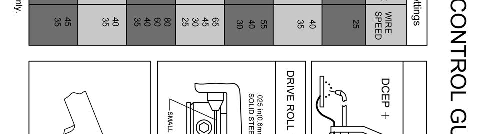
12 Figure 5 Figure Installing the Drive Roll (See Figure 7) The MIGPONY 140 is equipped with a reversible dual groove wire drive roll. The smaller groove is for.023 (0.6mm) solid wire only. The larger groove is for ( mm) solid or flux-cored welding wire. The default installation is.023 (0.6mm). When using ( mm) welding wires, the drive roll must be changed. 1. Power off the welding machine. 2. Unlatch the spring loaded pressure arm 1 and lift up the idle roll arm Loosen the hex bolt 3 that attaches the wire drive roll. Figure 7 4. Remove the wire drive roll 4 and flip the wire drive roll over so that the.030 (0.8mm) mark faces the user. 5. Reinsert the wire drive roll and tighten the hex bolt. 5.4 Installing the Welding Wire (See Figure 8, Figure 9, Figure 10) The MIGPONY 140 can use wire spools up to 8 (200mm) diameter with a maximum width of 2 (50mm). A spindle adapter is pre-installed for an 8 (200mm) diameter wire spool. The following wire installation should be performed only when the machine is powered off. 11
13 Installing an 8 (200mm) diameter wire spool. (See Figure 8) 1. Insert the wire spool 1 on the wire spindle 2. Ensure that the wire spool spindle tab 3 engages the hole in the wire spool. (Note: The wire spool will rotate clockwise when the wire is de-reeled.) Figure 8 Installing a 4 (100mm) diameter wire spool. (See Figure 8, Figure 9) 1. Remove the 2 (50mm) diameter spindle adapter 2 (See Figure 8) by first removing the wing nut Remove the plastic spacer Mount 4 (100mm) diameter wire spool directly onto 5/8 (16mm) shaft Reinstall the plastic spacer 6 and wing nut 5. (Note: The wire spool will rotate clockwise when the wire is de-reeled.) Figure 9 Thread the Welding Wire (See Figure 10) 1. Power off the welding machine. 2. Release the spring loaded pressure arm 1 and lift up the idle roll arm 2. Ensure the groove size matches the wire size. (See section 5.3 for wire drive roll installation) 3. Carefully pull out the welding wire 3 from wire spool. Maintain tension on the wire to prevent unwinding. 4. Cut starting end of the welding wire and straighten the lead section. You will need approximately a 4 (100mm) section of straightened wire. 5. Thread the straightened wire through the inlet guide tube 4 to the drive roll groove 5, and then guide the wire into the tube liner 6, continue to push the wire into the tail piece of the gun for approximately 6 (150mm). 12
14 6. Return the idle roll arm 2 back into the welding position and reset the spring loaded pressure arm 1. Figure Remove nozzle and contact tip from welding gun. 8. Power on the welding machine. 9. Straighten welding gun. 10. Depress trigger switch on welding gun to feed welding wire. When welding wire is exposed at the outlet side of the welding gun, release the trigger switch. 11. Power off the welding machine. 12. Reinstall the contact tip and nozzle. 13. Cut welding wire leaving approximately 1/4-1/2 (6-10mm) protruding from tip end of the gun. 13
15 5.5 Installing the Shielding Gas (See Figure 11) There are many different types of shielding gases that have been developed over the years, A general chart for common shielding gases and where they are used is below. Gas Argon Spray Arc Steel Short Circuiting Steel Application Short Circuiting Stainless Steel Short Circuiting Aluminum All positions 75% Argon + 25% CO2 CO2 Tri-Mix*** Flat & Horizontal* Fillet Flat & Horizontal* Fillet All Positions All Positions All Positions** All Positions *Globular Transfer **Single Pass Welding Only ***90% HE + 7-1/2% AR + 2-1/2% CO2 The flow regulator supplied in this package is suitable for 75% Argon + 25% CO2 mixed shielding gas which is used in the GMAW process. Obtain a compressed gas cylinder from your local welding supplier or from an authorized Thoroughbred Industrial Cylinder Exchange cage. For cage locations near you, visit 1. Power off the welding machine. 2. Secure the compressed cylinder to a wall, cylinder cart or other approved device with a chain or bracket system designed to prevent the cylinder from falling. 3. Once secured, remove cylinder cap. 4. Install flow regulator (CGA-580) to the supply valve on the cylinder and tighten with wrench. 5. Install one end of the gas supply hose to the outlet of the flow regulator and tighten. Connect the other end of the hose to the gas inlet located in the rear of the MIGPONY 140 machine. (The connector nipple 5/8-18 adapts to CGA-032) Ensure that the hose has no twisting or knotting. 6. Slowly twist the gas cylinder valve to start gas flow. Listen for leaking gas. If gas leakage is present, close valve disconnect flow regulator and hose and repeat steps 4 through Power on the welding machine. 8. Depress gun trigger switch and adjust the flow regulator to cubic feet per hour (CFH), (12-14 In/min). 9. When welding process is complete, close valve on gas cylinder. Depress gun trigger to release excess gas. Power off the welding machine. 14
16 Figure 11 15
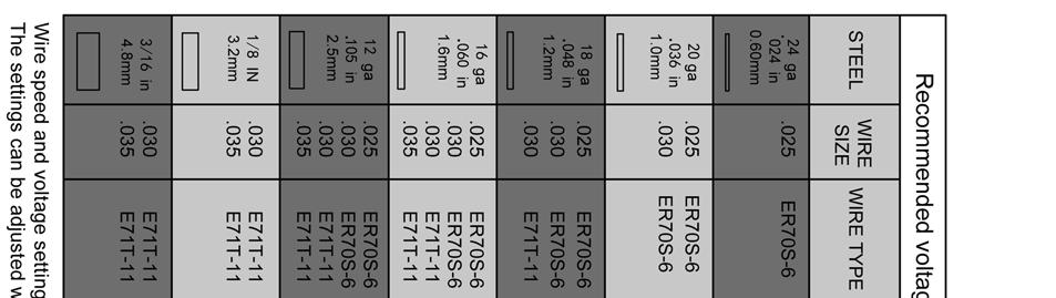
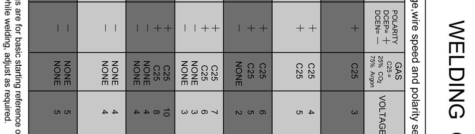
17 SECTION 6 WELDING PROCESS 1. Refer to the Welding Control Guide located on the inside right panel of the welding machine and in this manual (page 18). 2. Set output voltage, wire feed speeds and polarity on the welder according to the welding wire type in use. 3. When not using flux-cored wires, use proper shielding gas mixture. (See Section 5.5) 4. Connect work clamp to work piece(s) as close to the weld as practical. Ensure good metal to metal contact. 5. The welding gun should have free movement in the area of the piece(s) to be welded. 6. Power on the welding machine. 7. Make sure wire is no more than 1/2 (13mm) past end of nozzle and tip of wire is positioned correctly on seam. (See Figure 12) Figure 12 16
18 8. Always wear fire resistant protective safety clothing. Cover eyes with approved welding helmet. 9. Keep contact tip of the welding gun approximately 3/8 1/2 (10-13mm) away from weld seam. 10. Depress trigger switch on welding gun and begin to weld. 11. Release trigger switch to end welding pass. 12. When welding is complete, close valve on shielding gas cylinder. Depress trigger switch on welding gun to vent excess gas. 13. Power off the welding machine. 17
19 18
20 SECTION 7 TROUBLE SHOOTING Problem No weld output, wire does not feed, fan does not run No weld output, wire does not feed, fan motor continues to run No weld output, wire feeds Low weld output Wire feeding stops during welding Solution 1. Check that power cord is undamaged and plug is secure in receptacle. 2. Check fuse box and reset circuit breaker if open. 3. Check that power switch is turned to on position on welder. 1. Unit could be overheating. Allow fan to run for unit to cool down. Refer to Section 2 for duty cycle information 2. Check that gun is properly attached to welder. 3. Release gun trigger switch and cycle machine power off and back on. 1. Check that work clamp is secured to work piece with good metal to metal connection. 2. Check that polarity is set correctly. 3. Check that gun is properly connected to welder. 4. Replace contact tip. 1. Check that input voltage is correct or check for low line voltage. 2. Check that power switch is in on position on welder. 1. Straighten gun cable and replace damaged parts. 2. Check and adjust drive roll. Make sure correct groove is used. 3. Adjust tension on wire. 4. Replace contact tip if blocked. 5. Clean wire inlet guide or gun liner if dirty. 6. Check for obstructions at drive assembly. Find your nearest Thoroughbred Authorized Service / Repair Center by visiting 19
21 SECTION 7 WARRANTY INFORMATION LIMITED WARRANTY - MIGPONY 140 WELDER - LIMITED 1 YEAR / 90 DAY WARRANTY STATEMENT OF LIMITED WARRANTY. THOROUGHBRED INDUSTRIAL CYLINDER EXCHANGE MAKES EVERY EFFORT TO ENSURE THAT ITS PRODUCTS MEET HIGH QUALITY STANDARDS AND WARRANTS THE FOLLOWING TO THE ORIGINAL END USER (PURCHASER): NINETY (90) DAYS, FROM THE DATE OF PURCHASE, THAT THE GUN, LINER, WIRE FEED MECHANISM, WELDING CLAMPS, ELECTRODE HOLDER, CABLES AND ACCESSORIES PACKAGED WITH THE WELDER ARE FREE OF DEFECTS IN MATERIAL AND WORKMANSHIP. THIS DOES NOT APPLY TO CONSUMABLE PARTS, TIPS, NOZZLES AND WELDING WIRE. ONE (1) YEAR, FROM THE DATE OF PURCHASE, THAT THE TRANSFORMER AND RECTIFIERS ARE FREE OF DEFECTS IN MATERIAL AND WORKMANSHIP. THIS WARRANTY IS VOID IF THOROUGHBRED INDUSTRIAL CYLINDER EXCHANGE OR ITS AUTHORIZED SERVICE CENTERS FINDS THAT THE EQUIPMENT HAS BEEN SUBJECTED TO IMPROPER INSTALLATION, CARE, UNAUTHORIZED MODIFICATION, TAMPERING, INADEQUATE MAINTENANCE, IMPROPER STORAGE OR ABNORMAL USE. THIS LIMITED WARRANTY IS NOT TRANSFERABLE FROM THE ORIGINAL PURCHASER TO A SECOND OWNER. IN NO EVENT IS THOROUGHBRED INDUSTRIAL CYLINDER EXCHANGE LIABLE OR RESPONSIBLE FOR ANY INJURY, DAMAGE, OR LOSS RESULTING EITHER DIRECTLY OR INDIRECTLY FROM THE USE OR MISUSE OF THIS PRODUCT. THIS WARRANTY IS EXPRESSLY IN LIEU OF ALL OTHER WARRANTIES, EXPRESSED OR IMPLIED, INCLUDING THE WARRANTIES OF MERCHANTABILITY AND FITNESS. To take advantage of this warranty, the product or part must be returned to Thoroughbred Industrial Cylinder Exchange or its authorized service centers with transportation charges prepaid. Proof and date of purchase, with an explanation of the complaint, must accompany the merchandise. If our inspection verifies a defect, we will either repair or replace the product at our election or we may elect to refund the purchase price if we cannot readily or quickly provide purchaser with a replacement. Thoroughbred Industrial Cylinder Exchange will return repaired products at our expense, but if Thoroughbred Industrial Cylinder Exchange determines there is no defect, or that the defect resulted from causes not within the scope of our warranty, then the purchaser must pay the cost for the return of the product. This warranty gives the purchaser specific legal rights and they may also have other rights, which vary from state to state. 20
22 NOTES: 21
23 NOTES: 22
Operator s Manual Model ARC Amp DC Welder
 Operator s Manual Model ARC200 200 Amp DC Welder WARNING: Do not assemble, install, or operate this equipment without reading ALL of this manual and the safety precautions and warnings illustrated in this
NA-3N, NA-3NF, NA-3S, NA-3SF & NA-4 Troubleshooting Guide
 NA-3N, NA-3NF, NA-3S, NA-3SF & NA-4 Troubleshooting Guide IM278-TS September, 2006 Safety Depends on You Lincoln arc welding and cutting equipment is designed and built with safety in mind. However, your
Guidelines To Gas Metal Arc Welding (GMAW)
") Guidelines To Gas Metal Arc Welding (GMAW) WARNING ARC WELDING can be hazardous. This document contains general information about the topics discussed herein. This document is not an application manual
Guidelines To Gas Metal Arc Welding (GMAW) WARNING ARC WELDING can be hazardous. This document contains general information about the topics discussed herein. This document is not an application manual
EasyArc ARC 200/ ZX7-300/ ZX7-400 INVERTER MMA WELDING MACHINE OPERATION MANUAL. Hong Kong Easyweld Limited
 EasyArc ARC 200/ ZX7-300/ ZX7-400 INVERTER MMA WELDING MACHINE OPERATION MANUAL Hong Kong Easyweld Limited 1 CONTENTS - Contents & Declaration of Conformity 2 - Warnings & Safety Information 3 - General
INSTRUCTION MANUAL FOR WIRE WELDING MACHINE
 INSTRUCTION MANUAL FOR WIRE WELDING MACHINE IMPORTANT: BEFORE STARTING THE EQUIPMENT, READ THE CONTENTS OF THIS MANUAL, WHICH MUST BE STORED IN A PLACE FAMILIAR TO ALL USERS FOR THE ENTIRE OPERATIVE LIFE-SPAN
TIG200 DC WELDER INSTRUCTIONS. Item #20566
 TIG200 DC WELDER INSTRUCTIONS Item #20566 TIG Welding is the most controllable, efficient and versatile method of welding many metals including steel, stainless steel and more. Your EASTWOOD TIG 200 DC
LT-7 Lightweight Tractor
 Operator s Manual LT-7 Lightweight Tractor For use with machines having Code Numbers: K227, K395 and K395-1 Save for future reference Register your machine: www.lincolnelectric.com/register Authorized
INSTRUCTION MANUAL FOR WIRE WELDING MACHINE
 INSTRUCTION MANUAL FOR WIRE WELDING MACHINE IMPORTANT: BEFORE STARTING THE EQUIPMENT, READ THE CONTENTS OF THIS MANUAL, WHICH MUST BE STORED IN A PLACE FAMILIAR TO ALL USERS FOR THE ENTIRE OPERATIVE LIFE-SPAN
Item # ARC200i WELDER ASSEMBLY & OPERATING INSTRUCTIONS
 Item #20484 ARC200i WELDER ASSEMBLY & OPERATING INSTRUCTIONS The EASTWOOD ARC200I WELDER provides a convenient method of performing stick welding carbon steel or stainless steel. Inverter Technology provides
OPERATION MANUAL. A220 Arc Welding Machine. Serial Number: Where Purchase: Date of purchased:
 OPERATION MANUAL A220 Arc Welding Machine Serial Number: Where Purchase: Date of purchased: CONTENT 1.Safety... 2 2. Summary... 4 3. Electrical principle drawing... 5 4. Specifications... 6 5. Operation
Item #20295 ARC 80 WELDER ASSEMBLY & OPERATING INSTRUCTIONS
 Item #20295 ARC 80 WELDER ASSEMBLY & OPERATING INSTRUCTIONS The Eastwood Arc 80 provides a convenient method of performing arc or stick welding carbon steel or stainless steel. Inverter Technology provides
POWER PINNER BENCH HAND WELDER 7250 OPERATOR S MANUAL
 POWER PINNER BENCH HAND WELDER 7250 OPERATOR S MANUAL Copyright: November 20, 2018 Revised: Serial No. Gripnail Corporation An Employee Owned Company 97 Dexter Road East Providence, Rhode Island 02914-2045
WE11S GMA (MIG) Fillet Weld
 Fillet Weld") Uniform Procedures For Collision Repair WE11S GMA (MIG) Fillet Weld 1. Description This procedure describes methods for making and inspecting GMA (MIG) fillet welds on automotive steel. 2. Purpose The
Uniform Procedures For Collision Repair WE11S GMA (MIG) Fillet Weld 1. Description This procedure describes methods for making and inspecting GMA (MIG) fillet welds on automotive steel. 2. Purpose The
Inverter Welder Model: RXT135E
 Inverter Welder Model: RXT135E General instruction for installation use and maintenance Protect yourself and others by observing all safety information, warnings, and cautions. Failure to comply with instructions
Mig Welder Model: RXT175P
 Mig Welder Model: RXT175P General instruction for installation use and maintenance Protect yourself and others by observing all safety information, warnings, and cautions. Failure to comply with instructions
WE01S GMA (MIG) Plug Weld
 Plug Weld") Uniform Procedures For Collision Repair WE01S GMA (MIG) Plug Weld 1. Description This procedure describes methods for making and evaluating GMA (MIG) plug welds on all types of automotive steel. 2. Purpose
Uniform Procedures For Collision Repair WE01S GMA (MIG) Plug Weld 1. Description This procedure describes methods for making and evaluating GMA (MIG) plug welds on all types of automotive steel. 2. Purpose
Given a functional welder, instruction and demonstration of use, each employee will be able to:
 I. Competencies Given a functional welder, instruction and demonstration of use, each employee will be able to: A. Identify the major parts of the arc welder. B. Pass a written test of safety and operating
AHP WELDS USER MANUAL
 AHP WELDS USER MANUAL Alpha-TIG200X (version III) Contents 1. Safety... 2 2. About your AlphaTig 200X... 3 3. Parameters... 4 4. Panel Index... 5 5. Setup Instructions... 6 6. Operating Instructions...
WE21S GMA (MIG) Butt Joint With Backing
 Butt Joint With Backing") Uniform Procedures For Collision Repair WE21S GMA (MIG) Butt Joint With Backing 1. Description This procedure describes methods for making and inspecting GMA (MIG) butt joint with backing welds on automotive
Uniform Procedures For Collision Repair WE21S GMA (MIG) Butt Joint With Backing 1. Description This procedure describes methods for making and inspecting GMA (MIG) butt joint with backing welds on automotive
WE01A GMA (MIG) Plug Weld
 Plug Weld") Uniform Procedures For Collision Repair WE01A GMA (MIG) Plug Weld 1. Description This procedure describes methods for making and evaluating gas metal arc (GMA) plug welds (MIG plug welds) on all types
Uniform Procedures For Collision Repair WE01A GMA (MIG) Plug Weld 1. Description This procedure describes methods for making and evaluating gas metal arc (GMA) plug welds (MIG plug welds) on all types
TIG200 AC/DC WELDER INSTRUCTIONS. Item #20565
 TIG200 AC/DC WELDER INSTRUCTIONS Item #20565 TIG Welding is the most controllable, efficient and most versatile method of welding many metals including steel, stainless steel, aluminum and more. Your EASTWOOD
INSTRUCTION MANUAL FOR MG160 MIG WELDER
 INSTRUCTION MANUAL FOR MG160 MIG WELDER IMPORTANT: BEFORE STARTING THE EQUIPMENT, READ THE CONTENTS OF THIS MANUAL, WHICH MUST BE STORED IN A PLACE FAMILIAR TO ALL USERS FOR THE ENTIRE OPERATIVE LIFE-SPAN
!!Prompt attention to any injury usually will minimize what may become serious if neglected!!
 Safety in Welding !!Always report an accident regardless of how slight it may be!! Even a little scratch might lead to an infection, or a minute particle could result in a serious eye injury!!!!prompt
GMAW Unit Topics. During this overview, we will discuss the following topics:
 GMAW (MIG Welding) GMAW Unit Topics During this overview, we will discuss the following topics: Safety GMAW Basics Equipment Set-Up Welding Variables Process Advantages and Limitations AWS Connection National
6 Closet light. Model Due to continuing improvements, actual product may differ slightly from the product described herein.
 6 Closet light Model 95792 Assembly And Operation Instructions Due to continuing improvements, actual product may differ slightly from the product described herein. 3491 Mission Oaks Blvd., Camarillo,
Expressweld Inverter 200-E
 Expressweld Inverter 00-E MMA Welding Machine Operating Instructions and Spare Parts Manual Phase www.askaynak.com.tr Contents General Safety Instruction - 6 Genaral Specification 7-0 Description 7 Unpacking
Keep your head out of the gas. When you are welding, air extractor should be used to prevent inhalation of gas.
 Installation Instructions for 81542 TIG Welder 200 Page 1 Safety Caution! In the process of welding or cutting, there will be possibility of injury, so please take personal protection into consideration
ENel Sp. z o. o. - WROCŁAW DESIGN AND MANUFACTURE OF POWER ELECTRONIC DEVICES INVERTER WELDING MACHINE ENEL250A USER MANUAL DEALER:
 ENel Sp. z o. o. - WROCŁAW DESIGN AND MANUFACTURE OF POWER ELECTRONIC DEVICES INVERTER WELDING MACHINE ENEL250A USER MANUAL DEALER: . INTRODUCTION This manual contains information that will allow to take
INSTRUCTION MANUAL WARNING: BEFORE USING THE MACHINE READ THE INSTRUCTION MANUAL CAREFULLY!
 INSTRUCTION MANUAL WARNING: BEFORE USING THE MACHINE READ THE INSTRUCTION MANUAL CAREFULLY! SECTION 1 : PRODUCT AND COMPANY IDENTIFICATION PRODUCT NAME : SYNONYMS : PRODUCT CODES : Weldability ARC140i
Cutlass Fasteners, Inc. 83 Vermont Ave., Unit 6, Warwick, RI Tel: (401) Fax: (401) cutlass-studwelding.com
 Fax: (401) cutlass-studwelding.com") MODEL : A-58 ARC WELD GUN PART NO. : 602-378A SERIAL NO. : PLEASE READ THIS OPERATION AND MAINTENANCE MANUAL CAREFULLY BEFORE USING YOUR NEW CUTLASS STUD WELDER. COPYRIGHT CFI 2009 email: sales@ PAGE -
MODEL : A-58 ARC WELD GUN PART NO. : 602-378A SERIAL NO. : PLEASE READ THIS OPERATION AND MAINTENANCE MANUAL CAREFULLY BEFORE USING YOUR NEW CUTLASS STUD WELDER. COPYRIGHT CFI 2009 email: sales@ PAGE -
Rocker Tool Post ASSEMBLY AND OPERATING INSTRUCTIONS
 Rocker Tool Post 94540 ASSEMBLY AND OPERATING INSTRUCTIONS Machine tool shown in photo not included. Due to continuing improvements, actual product may differ slightly from the product described herein.
INVERTER IBGT MIG WELDING MACHINE OPERATION MANUAL
 ionmig 250 INVERTER IBGT MIG WELDING MACHINE OPERATION MANUAL IMPORTANT: Read this Owner s Manual Completely before attempting to use this equipment. Save this manual and keep it handy for quick reference.
booster EX2 / EX3 Operating Manual Extrusion Welder Weldy AG Galileo-Strasse 10 CH-6056 Kaegiswil / Switzerland TECHSPANGROUP
 booster EX2 / EX3 Extrusion Welder Operating Manual Weldy AG Galileo-Strasse 10 CH-6056 Kaegiswil / Switzerland TECHSPANGROUP Australia: Tel. 1-800 148 791 Fax. 1-800 148 799 www.weldy.com.au New Zealand:
Voltmaster Welder/Generators
 Voltmaster Welder/Generators Models W180H and W240 Owner s Manual June 2011 Table of Contents Voltmaster Welder/Generators 1 Introduction............................ 1 1.1 Read before using.....................
MIG 220 MIG 241. Arc Welding Machines OWNER'S MANUAL
 OWNER'S MANUAL Arc Welding Machines MIG 220 MIG 241 EN 60 974-1 EN 60 974-10 Dear customer We congratulate You for buying our top-quality welding device. You are kindly asked to carefully read this manual,
INSTRUCTION MANUAL FOR WIRE WELDING MACHINE
 INSTRUCTION MANUAL FOR WIRE WELDING MACHINE IMPORTANT: BEFORE STARTING THE EQUIPMENT, READ THE CONTENTS OF THIS MANUAL, WHICH MUST BE STORED IN A PLACE FAMILIAR TO ALL USERS FOR THE ENTIRE OPERATIVE LIFE-SPAN
Introduction Welding Brazing Cutting
 Welding Safety Introduction There are over 500,000 workers involved in some form of welding, cutting or brazing work. These are hazardous activities which pose a combination of both safety and health risks
ARC 80T OWNER S MANUAL
 ARC 80T OWNER S MANUAL 3/2018 WARNING: Read carefully and understand all ASSEMBLY AND OPERATION INSTRUCTIONS before operating. Failure to follow the safety rules and other basic safety precautions may
ST80i OWNER S MANUAL
 ST80i OWNER S MANUAL WARNING: Read carefully and understand all ASSEMBLY AND OPERATION INSTRUCTIONS before operating. Failure to follow the safety rules and other basic safety precautions may result in
Cutlass Fasteners, Inc. 83 Vermont Ave., Unit 6, Warwick, RI Tel: (401) Fax: (401) cutlass-studwelding.com
 Fax: (401) cutlass-studwelding.com") MODEL : PHM-12 ARC WELD GUN PART NO. : PHM-12 (PHM-12-RS) SERIAL NO. : PLEASE READ THIS OPERATION AND MAINTENANCE MANUAL CAREFULLY BEFORE USING YOUR NEW CUTLASS STUD WELDER. COPYRIGHT CFI 2009 email: sales@
MODEL : PHM-12 ARC WELD GUN PART NO. : PHM-12 (PHM-12-RS) SERIAL NO. : PLEASE READ THIS OPERATION AND MAINTENANCE MANUAL CAREFULLY BEFORE USING YOUR NEW CUTLASS STUD WELDER. COPYRIGHT CFI 2009 email: sales@
CONTENTS SAFETY RULES TECHNICAL INFORMATION...
 CONTENTS SAFETY RULES.... TECHNICAL INFORMATION......6. GENERAL EXPLANATIONS...6. COMPONENTS OF MONOSTICK 60i...6.3 DATA PLATE...7.4 TECHNICAL SPECIFICATIONS...7.5 ACCESSORRIES...7. INSTALLATION AND OPERATION...8.
CONTENTS SAFETY RULES TECHNICAL INFORMATION...
 CONTENTS SAFETY RULES.... TECHNICAL INFORMATION......6. GENERAL EXPLANATIONS...6. COMPONENTS OF MONOSTICK 60i...6.3 DATA PLATE...7.4 TECHNICAL SPECIFICATIONS...7.5 ACCESSORRIES...7. INSTALLATION AND OPERATION...8.
MULTIMIG 190 INSTRUCTION MANUAL 230V SINGLE PHASE
 MULTIMIG 190 INSTRUCTION MANUAL 230V SINGLE PHASE IN20810 2017 Chief Automotive Technologies CO9910.4 Rev. - 2/14/17 INSTRUCTION MANUAL FOR WIRE WELDING MACHINE IMPORTANT: BEFORE STARTING THE EQUIPMENT,
SECTION 10 WELDING AND CUTTING
 10.A GENERAL SECTION 10 WELDING AND CUTTING 10.A.01 Welders, cutters, and their supervisor shall be trained in the safe operation of their equipment, safe welding/cutting practices, and welding/cutting
TIG Series OPERATOR MANUAL. wilkinsonstar.com
 wilkinsonstar.com TIG Series DC MMA / TIG Welding machines Order code! TIG180(JT-180 / TIG200 (JT-200)!!!! TIG180(JT-180DV / TIG200 (JT-200DV) OPERATOR MANUAL Your new product Thank you for selecting this
LOAD RAMP 1000 LB. CAPACITY
 LOAD RAMP 1000 LB. CAPACITY 55424 ASSEMBLY AND OPERATING INSTRUCTIONS Safely roll Dirt Bikes and more into your Pickup! 3491 Mission Oaks Blvd., Camarillo, CA 93011 Visit our Web site at http://www.harborfreight.com
OPERATING INSTRUCTIONS
 www.r-techwelding.co.uk email: sales@r-techwelding.co.uk Tel: 01452 733933 Fax: 01452 733939 PRO-MIG250 PORTABLE INVERTER MIG/MAG/MMA WELDER OPERATING INSTRUCTIONS Version 2017-10 Thank you for selecting
SPEEDTEC 180C & 200C
 SPEEDTEC 180C & 200C OPERATOR S MANUAL IM3039 04/2016 REV07 ENGLISH Lincoln Electric Bester Sp. z o.o. ul. Jana III Sobieskiego 19A, 58-263 Bielawa, Poland www.lincolnelectric.eu Declaration of conformity
2200-Lb. Semi-Electric Stacker OWNER S MANUAL
 2200-Lb. Semi-Electric Stacker OWNER S MANUAL WARNING: Read carefully and understand all ASSEMBLY AND OPERATION INSTRUCTIONS before operating. Failure to follow the safety rules and other basic safety
ST200i OWNER S MANUAL
 ST200i OWNER S MANUAL WARNING: Read carefully and understand all ASSEMBLY AND OPERATION INSTRUCTIONS before operating. Failure to follow the safety rules and other basic safety precautions may result in
G009: Remove weld metal from plain carbon steel, using weld washing techniques.
 Welding 1 st Quarter DUTY A: Practicing Occupational Orientation A001: Follow safe practices. A002: Prepare time or job cards, reports, or records. A003: Perform housekeeping duties. A004: Follow oral
TIG Welding Machine. Introduction Risks & Hazards General Safety Operating Safety Maintenance Operating Procedures
 TIG Welding Machine This is a RESTRICTED item in NSW DET schools, where TEACHER USE ONLY is permitted. In VIC DEECD schools, this item can only be used by students under general supervision after the student
Part #12746 TIG 200 AC/DC WELDER ASSEMBLY & OPERATING INSTRUCTIONS
 Part #12746 TIG 200 AC/DC WELDER ASSEMBLY & OPERATING INSTRUCTIONS TIG Welding is the most controllable, efficient and most versatile method of welding many metals including steel, stainless steel, aluminum
INVERTER IBGT MIG WELDING MACHINE OPERATION MANUAL
 ionmig 141 INVERTER IBGT MIG WELDING MACHINE OPERATION MANUAL IMPORTANT: Read this Owner s Manual Completely before attempting to use this equipment. Save this manual and keep it handy for quick reference.
Guidelines For Gas Metal Arc Welding (GMAW) D. Processes. MIG (GMAW) Welding
 D. Processes. MIG (GMAW) Welding") 154557D 2018 01 Processes MIG (GMAW) Welding Guidelines For Gas Metal Arc Welding (GMAW) For product information, Owner s Manual translations, and more, visit www.millerwelds.com TABLE OF CONTENTS SECTION
154557D 2018 01 Processes MIG (GMAW) Welding Guidelines For Gas Metal Arc Welding (GMAW) For product information, Owner s Manual translations, and more, visit www.millerwelds.com TABLE OF CONTENTS SECTION
INVERTER MMA DC WELDING MACHINE WD U WD WD WD WD A/160A/180A/200A/250A
 INVERTER MMA DC WELDING MACHINE WD060111013U WD060111016 WD060111018 WD060111020 WD060111025 130A/160A/180A/200A/250A WD060111013U/WD060111016/WD060111018/WD060111020/WD060111025 Thank you for purchasing
FORM: OM-874D MIC-4 Interface Control
 OWNER S MANUAL FORM: OM-874D 093 324 MIC-4 Interface Control 2011 01 1. Safety Symbol Definitions DANGER! Indicates a hazardous situation which, if not avoided, will result in death or serious injury.
FW66 FORESTRY WINCH FW66. Owner s Manual 19/02/2016
 FW66 FORESTRY WINCH FW66 19/02/2016 Owner s Manual TABLE OF CONTENTS INTRODUCTION ---------------------------------------------------------------------------------- 2 INTENDED USE -----------------------------------------------------------------------------------
MONOSTICK 200İ.
 MONOSTICK 200İ PFC www.oerlikon.com.tr İÇİNDEKİLER SAFETY RULES... 2. TECHNICAL INFORMATION......6. GENERAL EXPLANATIONS...6.2 COMPONENTS OF THE MACHINE...6.3 DATA PLATE...7.4 TECHNICAL SPECIFICATIONS...7.5
INVERTER CONTROLLED WELDING POWER SOURCE DO NOT DESTROY
 MANUAL NO:P10322 OWNER'S MANUAL MAG FOR DIGITAL INVERTER DM350 MODEL: DM-350 P10322 INVERTER CONTROLLED WELDING POWER SOURCE DO NOT DESTROY IMPORTANT: Read and understand the entire contents of this manual,
Operation & Safety manual
 Operation & Safety manual MMA MMA 200 15-200Amps DC - Single Phase - 240V Inverter DC Arc Welder Congratulations on the purchase of your new PlasmaPart product We are delighted you have chosen us to provide
LOTOS TIG200-DC TIG/Stick Welder
 LOTOS TIG200-DC TIG/Stick Welder www.uwelding.com CONTENTS 1. Contents 1 2. Safety warning 2 3. Machine description 3 4. Technical parameters table 4 5. Installation instruction 5 6. Panel function instruction
SMAW. Shielded metal arc welding (SMAW) is commonly referred to as stick welding
 is commonly referred to as stick welding") SMAW EQUIPMENT SMAW Shielded metal arc welding (SMAW) is commonly referred to as stick welding An electric arc between the stick electrode and the base metal creates heat. Heat melts the base metal and
SMAW EQUIPMENT SMAW Shielded metal arc welding (SMAW) is commonly referred to as stick welding An electric arc between the stick electrode and the base metal creates heat. Heat melts the base metal and
USER S OPERATING AND INSTRUCTION MANUAL
 Grand Rapids, Michigan, U.S.A. 49504-5298 USER S OPERATING AND INSTRUCTION MANUAL MODEL 738 MINI CHIP SLICER 0738S20000-CV INDEX Section Description Document No. Page No. SAFETY INSTRUCTIONS --------------------------------------
TitanMig195/225 OPERATING MANUAL. TitanMig 195 MIG/Stick Welder Model No.TM195Issue. A 04/15. English. Operating manualen.
 TitanMig195/225 OPERATING MANUAL Operating manualen BrugsanvisningDA GebrauchsanweisungDE Manual de instruccioneses KäyttöohjeFI Manuel d utilisationfr Manualed usoit GebruiksaanwijzingNL BruksanvisningNO
DIE CAST ALUMINUM & THERMOPLASTIC SUMP PUMP
 INSTRUCTION MANUAL DIE CAST ALUMINUM & THERMOPLASTIC SUMP PUMP Vertical Switch Models WSSP3V 1/3 HP WSSP5V 1/2 HP Tethered Switch Models WSSP3 1/3 HP WSSP5 1/2 HP WARRANTY: PRODUCT DEFECTS COVERED 12 MONTHS
NO GAS/GAS MIG WELDER
 WARNING: Read these instructions before using the machine Welder is supplied setup for no gas welding NO GAS/GAS MIG WELDER MODEL NO: MIG 145/152/180/196 PART NO: 6014505, 6015153, 6015182, 6015200 OPERATION
Objectives. Identify hazards in the shop. Learn about protective clothing. Understand the dangers of fire, electricity, fumes, cylinders, and machines
 Welding Safety Objectives Identify hazards in the shop Learn about protective clothing Understand the dangers of fire, electricity, fumes, cylinders, and machines Explain how to avoid potential hazards
INSTALLATION AND OPERATION MANUAL
 Pneumatic Wheel Lift Model: RWL-50T REV. A PLEASE READ THE ENTIRE CONTENTS OF THIS MANUAL PRIOR TO INSTALLATION AND OPERATION. BY PROCEEDING YOU AGREE THAT YOU FULLY UNDERSTAND AND COMPREHEND THE FULL
High Temperature Aging Cell Instruction Manual
 High Temperature Aging Cell Instruction Manual Part No. 760140001EA Rev. D TABLE OF CONTENTS Section Page Figure 1 General Information... 1 2 Safety Considerations... 3 3 Un-pressurized Testing Procedure...
MMA ARC/TIG WELDING MACHINE INTIG
 MMA ARC/TIG WELDING MACHINE INTIG 250 INSTRUCTION MANUAL M/s WARPPP ENGINEERS PVT. LTD. B 1005, 10 TH FLOOR, WESTERN EDGEE II, NEAR METRO MALL, OFF.WESTERN EXPRESS HIGHWAY, BORIVALI (E), MUMBAI 4000 066.
SQ-1 INTELLIGENT ROOF
 SQ-1 INTELLIGENT ROOF ROOF TRUSS TABLE With Intelligent Gantry. Zone Eject Automated Jigging TRUSS TABLE Operators Manual FOREWORD This manual explains the proper maintenance of Square 1 Design Roof Truss
ENel Sp. z o. o. - WROCŁAW DESIGN AND MANUFACTURE OF POWER ELECTRONIC DEVICES INVERTER WELDING MACHINE ENEL170A USER MANUAL DEALER:
 ENel Sp. z o. o. - WROCŁW DESIGN ND MNUFCTURE OF POWER ELECTRONIC DEVICES INVERTER WELDING MCHINE ENEL70 USER MNUL DELER: . INTRODUCTION This manual contains information that will allow to take full advantage
7 PIECE TUBE FLARING KIT
 7 PIECE TUBE FLARING KIT Model 5969 Set up And Operating Instructions Diagrams within this manual may not be drawn proportionally. Due to continuing improvements, actual product may differ slightly from
XTI-201 AC/DC. Operator Manual
 INSTRUCTION MANUAL XTI-201 AC/DC Operator Manual ISSUE 2 Welcome Thank you and congratulations on choosing Parweld. This Owner s Manual is designed to help you get the most out of your Parweld products.
PSTICK80. Stick Welder with TIG Option. Assembly & Operating Instructions
 PSTICK80 Stick Welder with TIG Option Assembly & Operating Instructions READ ALL INSTRUCTIONS AND WARNINGS BEFORE USING THIS PRODUCT. This manual provides important information on proper operation & maintenance.
VISE MOUNTED. Model 97359
 VISE MOUNTED Small English wheel Model 97359 Set up And Operating Instructions Diagrams within this manual may not be drawn proportionally. Due to continuing improvements, actual product may differ slightly
Welding - Fire and Exposure Control
 Welding - Fire and Exposure Control PURPOSE Portland Community College has adopted its Welding Safety Chapter to ensure that employees are aware of the hazards associated with welding and ensure proper
LOTOS TECHNOLOGY. Plasma Cutter TIG Stick Welder CT520D.
 LOTOS TECHNOLOGY Plasma Cutter TIG Stick Welder CT520D www.uwelding.com Lotos Technology CT520D Quick Setup Instructions Power plug wiring: For either 110 or 220VAC, the GREEN wire is the ground wire.
ARC-110 Welder. Operating Manual
 ARC-110 Welder Operating Manual Congratulations on the purchase of your Chimera Arc Welder. With this welding unit you can now experience the many advantages of the Arc welding process. The ARC-110 has
SOP #: Welding Safety
 Welding Safety 1. Purpose / Background Welding, cutting and brazing operations have a number of safety and health hazards. These include the risk of fire and potential exposures to smoke, fumes, electrical
4 rotary milling table
 4 rotary milling table Model 97208 Set up And Operating Instructions Diagrams within this manual may not be drawn proportionally. Due to continuing improvements, actual product may differ slightly from
DISSTON WELDING PRODUCTS TIG/MMA-160/180/200/250D. Welding Machines
 DISSTON WELDING PRODUCTS TIG/MMA-160/180/200/250D Welding Machines FOR SAFE OPERATION: Keep the work area clean. Cluttered work areas invite injuries (indoor and outdoor). Consider the work environment.
AC/DC MULTI-200P AC/DC MULTI-220P
 THANKS FOR PURCHASING OUR PRODUCT AC/DC MULTI-200P AC/DC MULTI-220P DC INVERTER AC TIG/DC TIG/DC MMA/CUT 4 IN 1 MACHINE OPERATION INSTRUCTIONS SAFETY PRECAUTIONS Follow these precautions carefully. Improper
INSTRUCTION MANUAL MIG 160 / MIG 200 / MIG 300 / MIG 300S
 INSTRUCTION MANUAL MIG 160 / MIG 200 / MIG 300 / MIG 300S contents warning installation operation welding parameters troubleshooting warranty spare parts list torch consumable list 3 4 5 6 7 8 8 9-10 EC
Welding & Fabrication Tools Mini VaR Tool Kit
 With Volta Tools You Can Never Go Wrong! Fast and simple belt installation. Unique and versatile design - compact, rugged and easy-to-use. Designed for both shop and field use. Light-weight construction.
Synergic Inverter MIG welder
 Synergic Inverter MIG welder Features and Benefits MIG160i This versatile power source is suitable for various applications from general repairs to specific material types used in the body shop industry.
INSTALLATION AND OPERATION MANUAL
 PLEASE READ THE ENTIRE CONTENTS OF THIS MANUAL PRIOR TO INSTALLATION AND OPERATION. BY PROCEEDING YOU AGREE THAT YOU FULLY UNDERSTAND AND COMPREHEND THE FULL CONTENTS OF THIS MANUAL. FORWARD THIS MANUAL
Kiewit Building Group Newsletter 7/29/14 Volume 2 Week 31
 Kiewit Building Group Newsletter 7/29/14 Volume 2 Week 31 1 Welding joins two pieces of metal by the use of heat, pressure, or both. Arc Welding Shielded Metal Arc Welding (SMAW) Carbon Arc Welding (CAW)
1 YEAR FROM DATE OF PURCHASE
 INSTRUCTION MANUAL CAST IRON SUMP PUMP WSSPC5V 1/2 HP WARRANTY: PRODUCT DEFECTS COVERED 1 YEAR FROM DATE OF PURCHASE. RECEIPT AND PRODUCT DATE CODE REQUIRED FOR WARRANTY CLAIM. This pump is controlled
Owner s Manual & Safety Instructions
 Owner s Manual & Safety Instructions Save This Manual Keep this manual for the safety warnings and precautions, assembly, operating, inspection, maintenance and cleaning procedures. Write the product s
DRYWALL DOLLY 900 LB. CAPACITY
 DRYWALL DOLLY 900 LB. CAPACITY 94883 ASSEMBLY & OPERATING INSTRUCTIONS Due to continuing improvement, actual product may differ slightly from the product described herein. 3491 Mission Oaks Blvd., Camarillo,
HydroLink Watering System with Snake Tubing Installation, Operation & Maintenance Manual
 HydroLink Watering System with Snake Tubing Installation, Operation & Maintenance Manual This manual provides detailed instructions for safely installing, operating and maintaining the HydroLink Watering
SAMPLE. Troubleshooting Welding Processes. Topic 11. Welding Process Training Series
 Topic 11. Welding Process Training Series Troubleshooting Welding Processes Prepared by the Miller Electric Mfg. Co. Training Department. 2014 Miller Electric Mfg. Co. The contents of this publication
Operate Manual. DA-1600i Stud Welding Machine. DA-2000i Stud Welding Machine. DA-2500i Stud Welding Machine
 DA-1600i Stud Welding Machine DA-2000i Stud Welding Machine DA-2500i Stud Welding Machine Operate Manual KENT STUD WELDING CO., LTD 1 Content 1. Preface------------------------------------------------------------------------------
SMAW THEORY. Course # WELD1110
 Course # WELD1110 SMAW THEORY OBJECTIVES: At the completion of this course the student will be able to recall from lectures, demonstrations and audio visual aids the theory and applications of the (SMAW)
Operating Instructions
 Operating Instructions Series B37000 Hose Reels BB37118 L CB37118 L EB37118 L12D BB37122 L CB37122 L EB37122 L12D BB37128 L CB37128 L EB37128 L12D Dimensional Data C A B D Part # A B C D BB/CB37118 L 31
Weldmate HG2300MP Mig/Tig/Arc Inverter Welder
 Please dispose of packaging for the product in a responsible manner. It is suitable for recycling. Help to protect the environment, take the packaging to the local amenity tip and place into the appropriate
IN MIG IC Series Inverter CO2 MAG Welding Machines
 IN MIG IC Series Inverter CO2 MAG Welding Machines Operating Manual WARPP ENGINEERS PVT. LTD. B-1005, Western Edge II, Near Metro Mall, Off.Western Express Highway, Borivali (E), Mumbai-400 066. Tel: 91-22-28542272
DIGITAL PLATFORM SCALE
 DIGITAL PLATFORM SCALE 154 LB. WEIGHT CAPACITY Model 99969 Set up And Operating Instructions Not legal for trade or postal use. Diagrams within this manual may not be drawn proportionally. Due to continuing