Recommended installation procedures for Harvest and Beaumont Shake Note: Harvest Shake is 7 5/8 exposure and Beaumont Shake is 9 exposure
|
|
|
- Janis Copeland
- 6 years ago
- Views:
Transcription
.")

1 Page1 Recommended installation procedures for Harvest and Beaumont Shake Note: Harvest Shake is 7 5/8 exposure and Beaumont Shake is 9 exposure Do not begin installation until you have read and fully understand the procedures outlined in this Guide. Take special note of the Layout Patterns at the back of this guide and follow the layout for your mold number (marked on the product). Note: Snow can accumulate and slide off Euroshield roofing. Installers and homeowners should assess the need for snow retention systems and apply during the installation process. NOTE: HARVEST and BEAUMONT SHAKE SKIDS ARE NOT STACKABLE. PLEASE DO NOT DOUBLE- STACK SKIDS OR PLACE ITEMS ON TOP OF PRODUCT. Contact us at: th Street SE Calgary, Alberta, Canada T2C 2R2 Office (403) Toll Free (877) Fax (403) Website: info@euroshieldroofing.com G.E.M. Inc. is the manufacturer & distributor of EuroShield rubber roof roofing systems manufactured in Calgary, Alberta, Canada. CCMC (Canadian Construction Materials Council) Reg. Number R Ver S

2 Page2 TABLE OF CONTENTS Introduction - corporate profile - Feature / benefit page Components - spec data sheets - Packaging, handling Pre-installation - system introduction - Roof deck, structure, load, eave protection - ice dam, re-roofing, slope - underlay - ventilation - fastening, impact, shading, fade Installation - deck, eave protection, loading, valleys, protrusions, openings - Starter tile, field tile - Ridge, gable, hip caps - detail finishing, maintenance, flashing profiles
3 Page3 INTRODUCTION Corporate profile Calgary based Global Environmental Manufacturing Inc. (GEM), founded by Henry Kamphuis in 1999, has developed innovative technology to produce competitively priced, premium quality building products using approximately 95% recycled materials (e.g. recycled tires). GEM s unique technology, insulation properties and product design is capable of producing significant energy benefits and savings. The product is competitively priced while being ultra-environmentally friendly. GEM s proprietary, unique Reinforced Rubber Based Compound including carbon black forms the basis of all of GEM s products. Aside from adding durability and strength, Carbon Black is widely considered the best U.V. inhibitor in the world. GEM s EuroShield Roof is a pitched roofing system using rubber-based panels. Its unique selling features include unsurpassed durability and protection against all the elements and a simple installation resulting in a significant reduction in labour costs in comparison to other premium products. GEM s roofing system also provides an enhanced aesthetic appeal while providing superior lasting protection. Features and benefits Long lasting, durable Aesthetically pleasing Flexible and versatile Weather resistant Environmentally friendly Fast and easy to install Hail resistant with a 2 Hail damage warranty Very Lightweight (approx to 2.45 lbs per sq/ft) Affordable Potential discount on homeowners insurance policy Maintenance free Keeps your house cooler in the summer and warmer in the winter Fire resistant Increases the value of your home EuroShield is the most advanced roofing system in the market today.
4 Page4 Components Spec data sheet Harvest/Beaumont Shake Weight/pc 5.2 lbs. approx. Pieces/sq 48 approx. (Beaumont 40) Bundles/sq. 4 Pieces/Bundle 12 (Beaumont 10) Lbs/sq. 245 approx. (Beaumont 209 approx.) Length 40 approx. Width 17 approx. (Beaumont 20 approx.) Exposure/panel 2.12 sq. ft. (Beaumont 2.5sq.ft) Exposure/To-the-Weather 7 5/8 x 40 (Beaumont 9 x 40 ) Butt edge thickness is approximately ½ Ridge cap Weight.98 lb. approx. (Beaumont 1.25lb approx.) Length 15 approx. (Beaumont 18 ) Width 2 angles each side approx. 5.0 Exposure 7 5/8 approx. (Beaumont 9 approx.) Hip cap Weight/pc Length Width Exposure.98 lb approx. (Beaumont 1.25lb approx.) 15 approx. (Beaumont 18 approx.) 2 angles each 5.0 approx. 7 5/8 approx. (Beaumont 9 approx.) Starter Strip 2.10 lbs (40 W x 9.44 H) (Beaumont) 2.60 lbs (40 W x 11.1 H) Packaging and handling Harvest/Beaumont Shake 12 panel pieces per bundle (coverage/bundle = sq.ft) Beaumont Shake 10 panels per bundle (coverage/bundle = sq.ft) 4 bundles per square (100 to sq.ft TTW) 384 pcs per pallet (32 bundles) standard loading (Beaumont 400 pcs/pallet 40 bundles) 2047 lbs per standard pallet (approx. weight incl. pallet) (Beaumont is 2130 lbs)
5 Page5 Ridge Cap 12 caps per bundle (coverage/bundle = 7.5 lin.ft 9 lin.ft for Beaumont) Hip Cap 12 caps per bundle (coverage/bundle = 7.5 lin.ft 9 lin.ft for Beaumont) Starter Strip 12 pieces per bundle Coverage/bundle = 40 lin.ft Note: All products ordered by the bundle. PRE-INSTALLATION System Introduction This manual contains the acceptable requirements for GEM s Harvest/Beaumont Shake Roofing System. Installation specifications and details are designed for slopes 4/12 or steeper. Low slope applications less than 4/12 may warrant extra precautions; please contact GEM to qualify your particular circumstances and conditions. The recommended temperature range for installing Harvest/Beaumont Shake roofing products is - 10 degrees Celsius (14F) to +35 degrees Celsius (95F). Do not install Harvest/Beaumont Shake products outside of this temperature range. If installing on a Mansard or vertical slope, please contact us prior to installing. Cautionary Note: Harvest and Beaumont Shake uses an adhesive strip in addition to nails to fasten product. Like asphalt shingles, this adhesive requires sunlight and sufficient warmth to melt and bond to the panel below. A proper bond may not occur in the absence of heat; and accordingly there is the potential risk of blow-off should high winds set upon the roof prior to sealing of the adhesive strip. G.E.M. Inc. is not responsible for the blow-off of product due to installation in conditions that will not result in the proper bonding of panels. Should this be the case, it is permissible to fasten the panels using 18 gauge, galvanized 2 inch brad nails on the bottom corner of each shake section. This factory approved method will not void the Euroshield Limited Lifetime Warranty. It is important that the factory-applied adhesive makes full contact with the panel below for a proper bond. No exposed standard roofing nails are permitted when installing Euroshield products. Keep product covered prior to installation to avoid contamination of adhesive strip with dust/dirt.
6 Page6 This installation manual establishes a standard for the EuroShield System that meets or exceeds the requirements of CMHC and the National Building Code of Canada (2005). Installers must familiarize themselves with the contents of this installation manual in order that the EuroShield System is installed to its uncompromised standard. GEM reserves the right to limit or cancel the sale of EuroShield products should installation of the products not meet or exceed our standards. These recommended installation procedures may be amended as required from time to time. As long as the minimum standards of installation are adhered to in accordance with this installation manual, installation practices and procedures may be modified; however, installers must comply with local building code standards in keeping with the needs and requirements for their area and application. ROOF DECK The roof area shall be sheathed with plywood, OSB or equivalent; minimum 10mm (3/8 ) thick satisfying the requirements of the National Building Code, cut flush with fascia at both eaves and gable. Distance between support trusses or joists should not exceed 600mm (24 ). Our technical department for individual attention should qualify distances exceeding 600mm (24 ). Sheathing shall be fastened and clipped according to local building codes. STRUCTURE AND LOAD REQUIREMENTS There are no special structural changes or enhancements to make or special load requirements necessary for GEM s EuroShield Roof. The roof structure and load requirements must meet the requirements of the National Building Code (or corresponding province/state building code where applicable). EAVE PROTECTION Eave protection materials must conform to National Building Code. Install protection membrane material along all eaves overhanging fascia 25mm (1 ). End laps of material are to be 150mm (6 ) and sealed according to manufacturer s instructions. Only film surfaced material should be used so a separation exists between the bitumen and Euroshield panels. Roof systems will sometimes fail due to the formation of ice dams. Ice dams are formed by the continuous melting and freezing of snow and the backing up of frozen slush from the gutters, due to heat escaping from the house. The melted water flows under the snow and freezes as it reaches the unheated soffit, thus creating the ice dam. When this occurs, water can be forced under the panels and into the attic, causing damages to the home s ceilings, walls, insulation, gutters, eaves and roof.
7 Page7 To reduce ice dam formation and help minimize ice dam problems: 1. Keep the attic space cold by insulating it from the warm house interior, thus reducing or eliminating snow melt. 2. Use high heel trusses, insulate to the outside of the plates and install cardboard baffles to ensure ventilation at the eaves. 3. Ensure that the outer edges of the gutters or eavestroughs are lower than the slope line to allow snow and ice to slide clear. Also ensure gutters are free of debris. Reference: Canadian Mortgage and Housing Corporation, Roofing and Flashing Problems, publication NHA In areas where snowfall occurs, snow guards may be required to help prevent slides from the roof surface to the ground below. If snow guards are to be used with the Euroshield product, they should be applied at the time of installation. It is the responsibility of the installation contractor, in conjunction with the homeowner, to determine the suitability of installing snow guards on the roof, unless specified in the local building code. GEM Inc. assumes no responsibility for the supply or install of these devices on the roof. In high snow areas with a ground snow load greater than 3.5 kpa as identified in Chapter 1 of the supplement to the National Building Code of Canada, the eaves protection must extend from the edge of the roof to a minimum distance of 1700mm (67 ) up the roof to a line not less than 1100mm (43 ½ ) inside the inner beam. Fasten and adhere the protection material to the sheathing sufficiently to prevent wind up lift and damage with hot galvanized or coated fasteners. Valleys utilize the same materials as eaves protection. Material is applied parallel to valley centerline with half roll width on each side of the centreline and overhanging the fascia and eaves 25mm (1 ). In areas with high snowfall combined with freeze thaw conditions use double roll width extending 860mm (34 ) to both sides including 100mm (4 ) lap at centreline.

8 Page8 RE-ROOFING As Euroshield is a permanent roofing product; it is imperative that the existing roof and the underlying roof structure are inspected to determine whether the substrate has not rotted and is of enduring quality. EuroShield should not be installed over an existing roof covering; asphalt shingles, shakes or other. Remove existing roof covering to ensure trusses, sheathing fascia and other components including masonry, plumbing and mechanical are in good repair to support the EuroShield System through its durable lifetime. In any case, the existing roof covering (asphalt, cedar, pine or other) must be removed and repairs or replacement of deteriorated components undertaken prior to installation of a Euroshield roof. Failure to do so will void the Euroshield product warranty. SLOPE EuroShield was designed to be installed on roofs with a slope of 4/12 or greater as described in the National Building Code. For low slope application (less than 4/12), contact our technical department at (877) prior to the installation of Euroshield products. The installation of Euroshield roofing products is not recommended on sloped roofing with a pitch of 2/12 or less.
9 Page9 UNDERLAY In standard applications, whether installing on new sheathing or on existing sheathing, install ice dam protection and woven synthetic (plastic/polymer/fiber reinforced) underlay, as described in the National Building Code (or corresponding province/state code where applicable). Note that though your building codes may not require underlay on the entire roof, GEM s warranty does require it. There are many reasons why the use of underlayment prior to applying Euroshield makes good roofing sense. Underlayment protects the wooden deck from the moisture penetration until the EuroShield is applied, thus greatly reducing problems to structure. Installing underlayment helps to minimize picture framing, i.e. the visible outline of deck panels cause by irregularities in roof construction. The water resistance of underlayment provides secondary protection by helping to shield the deck from wind-driven rain. Underlayment offers protection to the EuroShield from the resins that can be released by the wood decking. The underlayment material should meet the following industry standard: Synthetic Woven Underlayment - In accordance with approved alternative to ASTM D226, Type 1, 15# or type 2, 30# asphalt saturated organic felts, nonperforated] The proper application techniques recommended by the manufacturer should be followed to ensure optimum performance of underlayment. The underlayment above eaves protection should be installed in minimum 1118mm (44 ) widths, parallel to eaves lines with a minimum 100mm (4 ) head lap and 150mm (6 ) side lap. Fasten underlayment to roof deck with galvanized nails or staples sufficient to prevent wind lift and damage prior to installation. Extend underlayment a minimum 150mm (6 ) up all walls, chimneys, skylights, etc. and seal corners with DuraSil Sealant (or equivalent sealant). Underlayment must overlap valley protection 18 past centreline. Any underlayment damage must be repaired or replaced prior to Harvest/Beaumont Shake application. For low slope underlay requirements see manual sections on Slope and Eave Protection. VENTILATION The proper ventilation of the attic area is an essential factor in attaining the maximum service life available from the building materials used in the roof assembly, in addition to improving heating and cooling costs. Overlooking this consideration may result in premature failure of the roofing system due to: 1) Accelerated aging of the EuroShield System. 2) Rotting of the wood structure, wet insulation due to condensation. 3) Buckling of the roof deck.
10 Page10 Failure to adequately ventilate the attic space to meet minimum local building code standards may result in premature product failure and void your Euroshield product warranty. In the wake of technical advances and the proliferation of energy conservation measures, the trapping of air and moisture in the attic is problematic. Improved insulation and better weather stripping are the two major reasons for this occurrence. To correct this problem one needs to provide proper ventilation to ensure free and unobstructed air movement beneath the roof surface. The National Building Code (Canada) requires that all roof and attic spaces above an insulated ceiling shall be ventilated with openings to the exterior to provide unobstructed vent areas of not less than 1 sq.ft./300 sq.ft with a suggested minimum of 1sq.ft/200 sq.ft. The vents shall be uniformly distributed on opposite sides of the building, in such a way that approximately 50% are near the lower part of the roof (inflow) and approximately 50% are near the ridge (outflow). Cathedral ceilings covered with the EuroShield System require adequate ventilation like any other roof to prevent damage to the products or structure. There should be a minimum space of 2 inches between the roof sheathing and the insulation to allow for unobstructed air movement. When vapour barrier is used, cathedral ceilings require a minimum total net area for the inlet and outlet vents equivalent to 1/300 of the total ceiling area with a suggested minimum of 1/200. Cross ventilation should be ensured by locating half the required vent area at the eaves and the other half at the ridge. Vent manufacturers should be consulted on the proper use of their products. FASTENING THE HARVEST SHAKE (mold #22/#23) IS ATTACHED USING NINE (9) 1 ¾ galvanized nails in the locations shown in the image below. (Note that Mold #24 Sawn-Look utilizes 8 nails per panel.) THE BEAUMONT SHAKE USES SIXTEEN (16) NAILS IN A DOUBLE ROW PLACEMENT, ONE ROW 4 INCHES ABOVE THE FIRST ROW LOCATED JUST ABOVE THE EXPOSURE LINE. (See Illustration for nail placement). Nails should be placed ¾ above the open keyways as indicated by the X or O and by the arrows. Care should be taken to make sure nails are driven flush with the surface of the Shake panel. Nails driven below the panel surface such that a depression or cavity is created in the rubber panel, or nails driven on angle can reduce the surface contact area for proper bonding of the adhesive strip. If using a compressor-operated nailer, adjust pressure to the point where the nail is driven flush with the panel surface. No exposed standard roofing nails are permitted when installing Euroshield products.


11 Page11 MOLD #22 AND #23 SPLIT-LOOK PANELS NAIL PLACEMENT INDICATED BY AN X HARVEST SHAKE ALWAYS PLACE NAILS WHERE INDICATED BY AN X or O ( Do not skip any nail locations) Harvest Shake MOLD #24 sawn-look PANEL NAIL PLACEMENT INDICATED BY AN X or O

12 Page12 Each Eave/Rake/Valley Starter Strip is fastened using nine (9) 1 ¾ galvanized roofing nails in the locations indicated in the illustration below. The starter strip is applied over the ice/water barrier at the eave edge and over the metal valley as indicated in the deck detail illustrations contained in this guide. Be sure to caulk the outside edge of the underside of the starter and the underside and topside edge of the valley starter and rake starter as indicated in the illustrations in this guide.
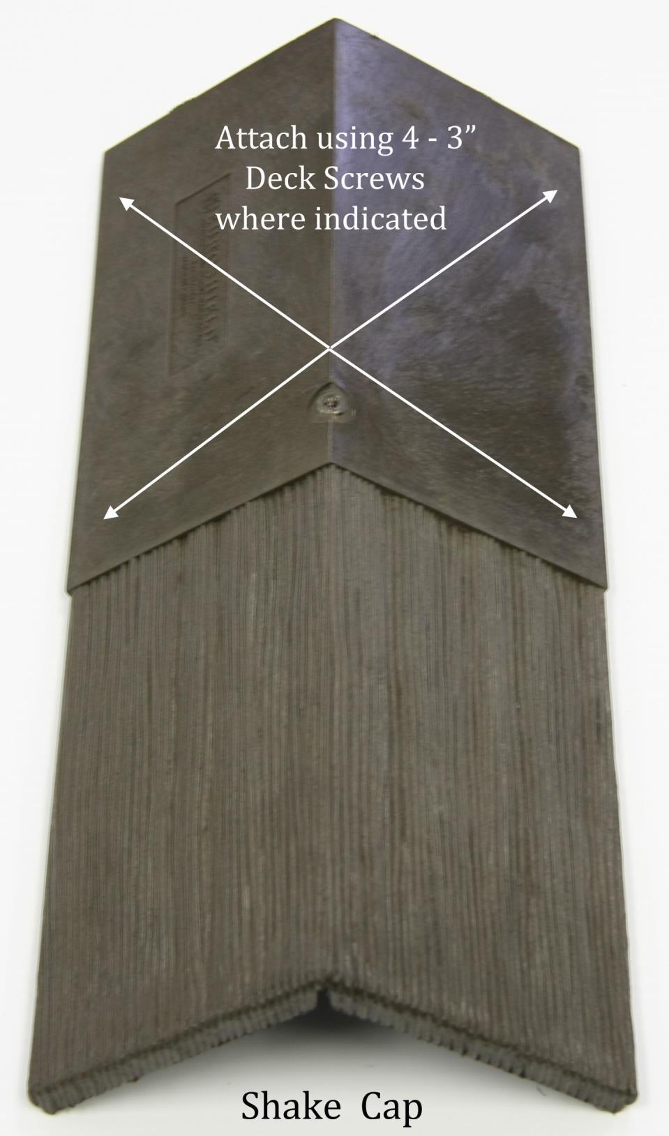
13 Page13 Gable end (rake) is prepared by applying the starter strip over the woven synthetic underlayment vertically along the rake edge with the thicker portion to the outer edge of the rake and overlapping the rake edge by ¾. A bead of DuraSil Sealant (or equivalent sealant) is applied along the outside edge in a continuous bead from eave edge to roof peak prior to installation of the field panels. Valleys are prepared in similar fashion with the starter strip running vertically up the valley, placed over the metal valley, 2 inches out from the center on both sides of the valley. The thicker portion of the starter panel is closest to the center of the valley. DuraSil Sealant (or equivalent sealant) is applied along the underside and topside inside edge in a continuous bead from eave edge to top edge of the valley prior to installation of the field panels. Each hip cap is fastened using four (4) 3 galvanized deck screws, (2) on each side, placed so that the next hip cap covers the exposed fastener heads. Each ridge cap is fastened using four (4) 3 galvanized deck screws, (2) on each side, so that the next hip cap covers the exposed fastener heads. IMPACT AND HAIL RESISTANCE EuroShield demonstrates excellent resistance to mechanical impact and hail. The rugged and elastic nature of the rubber base material should weather the heaviest of storms. SHADING
14 Page14 As a roof is viewed from different angles, and/or different lighting conditions, certain areas may appear darker or lighter. This inconsistency in colour has been designed to achieve the authentic look of shake. INSTALLATION INSTRUCTIONS ROOF DECK See pre-installation and preparation section regarding material requirements and codes applicable. Check all roof gables for squareness. Check eave edge for squareness. Before work begins, the work of all other trades on the roof should be complete. EAVE PROTECTION AND UNDERLAY See pre-installation and preparation section regarding material requirements and codes applicable. Check and repair if necessary any damage to eave protection or underlayment, be sure the underlayment overhangs 25mm (1 ), that head laps and side laps are sufficient to code and underlay extends up walls, chimneys, skylights, etc. LOADING Always load EuroShield products toward the peak in such a manner as to not overload any one section of the roof, keeping in mind that the application will start at bottom of the roof.

15 Page15 Distribute materials to allow for close proximity during installation. Do not overlap bundles on the roof. Each bundle should lay flat on the roof. VALLEYS, PROTRUSIONS AND OPENINGS Take extra care to make sure underlayment and eave protection is sealed and watertight at all valleys, chimneys, protrusions and openings. Apply one layer of peel and stick to the valley with 24 to 36 inch metal valley on top. Apply Valley Starter Strip up both sides of the valley, 2 inches out from the center of the valley, after applying a continuous bead of caulk to the roof deck 3 inches out from the center of the valley from ridge to eave. Nail starter where indicated on the panel. Start the Shake panel 2 inches from the centre of the valley and crop the top of each piece similar to asphalt shingles. If a chimney is more than 750mm (30 ) wide, building code demands a saddle be built for better drainage. A saddle need not be installed if a sheet metal flashing is used that extends up the chimney to a height equal to not less than one sixth the width of the chimney, but not less than 150mm (6 ), and up the slope to a point equal in height to the flashing on the chimney, but not less than 1.5 times the slate exposure. Provincial building code demands flashing installation on all roof/wall intersections, thickness described previously.
16 Page16 Circular chimneys are flashed using a metal flashing (provided by mechanical contractor). Flange of flashing is to be woven into EuroShield courses at top of the slope and sealed around complete flange with DuraSil Sealant (or equivalent sealant). Plumbing vent stacks are flashed using a metal vent pipe flashing, metal or a flexible rubber flashing (normally supplied by mechanical contractor,) and woven into the EuroShield courses at the top of the slope. Note if mechanical contractor is flashing, be sure they are on site before commencing EuroShield application. Ensure all other protrusions are properly flashed and woven into the Euroshield courses and sealed in a lightweight manner. For unique circumstances contact G.E.M. s technical department. VENT PIPE INSTALLATION (Top and sides of pipe flashing covered by panels should be overlapped with 6 strip of ice and water membrane prior to installing roof panels)
17 Page17 ATTIC VENT INSTALLATION (Top and sides of attic vent flashing portion covered by panels should be overlapped with 6 strip of ice and water membrane prior to installing roof panels)
18 Page18 FLASHING DETAIL
19 Page19 CHIMNEY INSTALLATION
20 Page20 EAVE STARTER STRIP After the roof deck has been prepared and ice/water membrane and woven synthetic underlayment is in place (see illustrations to follow), begin the installation of the starter strips for eave, valleys and rake edges. Starting at the left side of the roof eave edge, chalk a straight line 222mm (8 ¾ ) from the lower most point of the eave edge. Align the top edge of the eave starter strip with the chalk line such that the bottom edge of the starter extends ¾ past the bottom of the eave edge. Install eave starter strip panels over the ice/water membrane maintaining a ¾ overhang along both eave edge and rake edge. Apply a continuous bead of caulk to the underside eave edge prior to installing the starter strip as shown in the Gable and Eave Edge illustration. This first piece must be a part-panel so that the starter keyway (space between panels/tiles) does not line up with a keyway of the first full course of Harvest/Beaumont Shake going down directly on top of the starter row. Fasten using 9-1 ¾ roofing nails as shown above. Nails should penetrate the Fascia Board.

21 Page21 Moving up the rake edge, install the rake starter such that it overhangs the gable edge by ¾. The eave starter strip will then butt up to the rake edge starter. Apply a continuous bead of caulk along the rake edge on the topside of the Starter Strip as shown in the illustration below as field panels are installed up the roof. Continue with gable starter up the roof to the peak, fitting the panels together as shown in the illustration below (Gable and Eave Detail).
.")
22 Page22 Install the first Harvest/Beaumont Shake panel such that the raised nibs on the back of the panel touch the top of the eave starter strip below. This is best achieved by laying the panel on the roof deck and then lowering down until the raised nibs just touch the top edge of the panel (See photo below). Slide the panel sideways until tabs touch the adjacent panel. The first full panel will extend ¾ past the gable edge. Nail the first panel in place using 1 ¾ galvanized roofing nails where indicated in the diagram (see Fastening section). (Panels have an SBR adhesive strip along the underside of the butt edge. During installation, after the panel is nailed down, the butt edge of the panel must be pressed down to make firm contact with the course below. Over a short period of time, in combination with the sun s heat, this adhesive will bond the courses together in a manner similar to that observed with asphalt shingles.) The spacer tab(s) on the left of the panel will be trimmed off at this point with a knife so the edge is smooth. The next panel will then be lowered down until the alignment nibs on the back of the panel touch the top portion of the eave starter in the same manner as the first panel and then slide the panel gently to the left so that the tab touches the side of the first panel. Press the butt edge of each panel section down so that the adhesive strip makes contact with the panel below. Continue in this manner until the right gable is reached and trim the last panel such that you have ¾ overhang on the gable end and are flush with the edge of the eave starter overhang. Continue up the roof course-by-course following the layout pattern for the mold number you received in your shipment (shown on front of panel).


23 Page23 Do not nail the face of the panel as the fascia will have to be installed under the drip edge.
24 Page24 If working left to right out of a valley, place the top left portion of the panel in the valley such that the diagonal cut down, 2 inches out from the centerline of the valley, from left to right cuts through the entire panel. The overlap on each piece is fitted into the overlap of the preceding one. At the ends of the courses trim panels (using a power saw or knife), to be flush with the edge. Care should be taken to keep the cuts straight. Panels are installed using nine (9) 1 ¾ galvanized roofing nails for Harvest Shake Mold #22 & #23 and eight (8) 1 ¾ galvanized roofing nails for Harvest Shake Mold #24 and the Beaumont Shake uses 16 nails in a double row fashion (see illustration above and in Fastening section). ROOF JACKS Roof Jacks may be fitted and removed in the same manner as with asphalt shingles. Upon reaching the peak of the roof, the last row of panels may have to be trimmed along the upper edge, flush with the ridge. Walls, chimneys, plumbing vents, attic vents, skylights etc. must be flashed and sealed as described in other sections of this manual, and woven into the Euroshield as the field panels are progressively installed up the slope of the roof.
25 Page25 RIDGE CAP (Note that Harvest/Beaumont Shake ridge and hip caps are the same however the Beaumont Cap is a 9 exposure) Caps can be installed over ridge venting. Please consult the ridge vent manufacturer for details on application. Note that the caps cover approximately 4.5 on each side. When the field panels are completely installed the ridge cap panels can be added. Ridge caps are installed starting from east or south side so they do not face prevailing winds. Each cap is fastened using four (4) 3 galvanized deck screws, two (2) on either side. The last cap must be face fastened using a dab of DuraSil (or equivalent sealant) under the cap at the fastening point and a 2 inch brad nail fastened through the cap and sealant.
26 Page26

27 Page27 HIP CAP The hip caps are the same piece as the ridge caps and are installed in the same manner as ridge caps. Beginning at the eave, overhang the first cap by ¾ and fasten where indicated in the diagram on page 24. The first cap is additionally fastened with two 2 brad nails, one on either side of the cap, near the butt edge as shown in the illustration. Place a dab of DuraSil (or equivalent sealant) under the cap at the fastening point prior to placing the brad nail. Place the next cap above the first and lower until the nibs on the underside of the cap touch the top portion of the cap below. The correct exposure of 7 5/8 for the Harvest Shake (Beaumont Shake is 9 ) is now set automatically. Continue working your way up the hip in similar fashion, fastening each cap with four (4) 3 galvanized deck screws, two (2) on each side such that the overlapping cap covers the fastener. Note that the caps are notched at the butt edge to allow for variable pitch applications and the notch can be cut (widened) further to allow for steep pitch applications. Caps have a molded V on the underside as can be seen in the illustration above. Cutting along the butt-side edge of this V will allow for a clean edge (no exposed cavities) when installing the first hip cap at the eave edge where 2 roof planes meet at 90 degrees.
28 Page28 HIP DETAIL AT RIDGE VALLEYS Width - 24 to 36 for Open Types of Metal: Copper Stainless Steel Color Clad Steel Color Clad Aluminum Note: When fastening shingles in valley areas, nail as far away from the centre of the valley as possible to avoid penetrating the valley metal. DETAIL FINISHING The above instructions should conclude the application of the EuroShield System, excepting the completion of the details on walls, chimneys, skylight, vents etc. Pay special attention to and follow the layout pattern found at the back of this guide, specific to the mold number. They should be sealed with DuraSil Sealant (or equivalent sealant) and be flashed appropriately in accordance with C.R.C.A. Standard specifications, in conjunction with G.E.M. detail drawings contained within this Guide. Plumbing vents must be sealed to the pipes with DuraSil Sealant (or equivalent sealant) and clamped according to pipe flashing manufacturer s instructions.
29 Page29 MAINTENANCE The EuroShield System requires very little ongoing maintenance. Renew DuraSil Sealant (or equivalent sealant) on details and exposed fastener heads from time to time as required, maintain gutters, troughs, downpipes and drain to remain free of debris so drainage water flows away unrestricted. Should alterations be required involving the roof as time goes on, please contact G.E.M. s technical department for assistance. Repairs performed with non EuroShield system components or incompatible materials will void the EuroShield warranty.
30 Page30
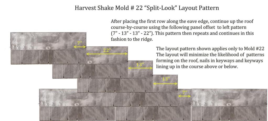
31 Page31 Panel Layout Pattern The layout patterns below for the Harvest Shake and Beaumont Shake helps minimize the effect of discernable patterns and ensures the individual keyways on each course do not line up with the keyways in the course below, taking care not to expose nails in the open keyways below. In no case shall a panel joint (area where two panels meet in a course) be within 5 inches of the panel joint in the course below or above. Panels have an SBR adhesive strip along the underside of the butt edge. During installation, after the panel is nailed down, the butt edge of the panel must be pressed down to make firm contact with the course below. Over a short period of time, in combination with the sun s heat, this adhesive will bond the courses together in a manner similar to that observed with asphalt shingles. HARVEST SHAKE MOLD #22, #23, #24 and Beaumont Shake (Mold # 25, #26 and #27) LAYOUT PATTERNS (On Pages 31 and 32) The illustrations below are examples of a recommended panel offset/layout. There are 4 different mold patterns. Please make sure you match the layout pattern to the mold number on the product you have received. It is marked on the front side of the panel. It is intended to show how each course should be started to minimize the effects of patterning on the roof. Be sure to fasten the nails above the keyways (refer to nailing diagram on page 11) such that they are not visible in the keyway as the next course of panels is applied. Some adjustments may be required to achieve this. It is recommended to keep panel-to-panel joints (where 2 panels meet in a course) five (5) inches or more from a similar panel-to-panel joint in the course below.
 387-7667 prior to beginning installation.")
32 Page32 DO NOT install straight up the roof, as is often done with asphalt shingles, offsetting the same distance each course as you will create a step-like or ladder effect which will be visible on the roof. If you have any questions regarding the layout, or any other installation-related questions, please call our North American Toll Free Number (877) prior to beginning installation. Thank you for your purchase of Euroshield roofing products. Please Note: Mold #22 and Mold #23 (Split-Look) require 9 nails per panel as indicated on the panel by an X or an O. Mold #24 (Sawn-Look) requires 8 nails per panel as indicated on the panel by an X or O. Beaumont Shake (Mold #25, #26, and #27) requires 16 nails per panel as indicated on the panel by an X or O Always place nail where indicated by an X or O do not skip any nailing locations Follow the row numbers as indicated on the top section of each panel for the offsets shown below.

33 Page33


34 Page34 Harvest Shake Mold #24 utilizes 8 nails per panel as indicated by an X The Beaumont Shake (Mold #25, #26, and #27) utilizes 16 nails per panel as indicated by an X or O.
Recommended installation procedures for Granville Slate Mold #53
 Page1 Recommended installation procedures for Granville Slate Mold #53 Do not begin installation until you have read and fully understand the procedures outlined in this Guide. Take special note of the
Euroshield Environmentally Friendly Rubber Roofing
 Page1 Euroshield Environmentally Friendly Rubber Roofing Recommended installation procedures for EuroShake and EuroSlate Do not begin installation until you have read and fully understand the procedures
Recommended installation procedures for Ranchlands Shake and Rundle Slate (formerly EuroShake and EuroSlate)
") Page1 Recommended installation procedures for Ranchlands Shake and Rundle Slate (formerly EuroShake and EuroSlate) Do not begin installation until you have read and fully understand the procedures outlined
Page1 Recommended installation procedures for Ranchlands Shake and Rundle Slate (formerly EuroShake and EuroSlate) Do not begin installation until you have read and fully understand the procedures outlined
Installation Guide. Titan Slate. Rev102606
 Installation Guide Titan Slate Rev102606 Titan Manufacturing 200 bella citta blvd. Davenport, fl 33897 Phone: (920) 716-1411 Fax: (866) 601-4395 www.titanroofsystems.com This document includes the recommended
EUROTILETM. Recommended Installation Procedures
 EUROTILETM TM Recommended Installation Procedures IMPORTANT: DO NOT BEGIN INSTALLATION BEFORE REVIEWING PATTERN LAYOUT SHEET AT THE END OF THIS INSTALLATION GUIDE 9330 48 th Street SE Calgary, Alberta,
Pacific Tile Counter Batten and Batten
 Pacific Tile Counter Batten and Batten INSTALLATION GUIDE www.gerardusa.com INSTALLATION NOTIFICATION The installation procedures demonstrated in this manual are recommended methods for the installation
Pacific Tile Counter Batten and Batten
 Pacific Tile Counter Batten and Batten INSTALLATION GUIDE www.gerardusa.com Page2 INSTALLATION NOTIFICATION The installation procedures demonstrated in this manual are recommended methods for the installation
INSTALLATION GUIDE.
 INSTALLATION GUIDE www.gerardusa.com INSTALLATION NOTIFICATION The installation procedures demonstrated in this manual are recommended methods for the installation of the Gerard Canyon Shake counter batten
Installation Guide. Mission Tile. Distributed by: BEST MATERIALS LLC, Phoenx AZ
 RPM ROOFING Installation Guide Mission Tile Distributed by: BEST MATERIALS LLC, Phoenx AZ 602-272-8128 800-474-7570 www.bestmaterials.com Table of Contents OVERVIEW...1 CAUTION...1 DISCLAIMER...1 PRODUCT
Classic and NB Tile Counter Batten and Batten
 Classic and NB Tile Counter Batten and Batten INSTALLATION GUIDE www.gerardusa.com INSTALLATION NOTIFICATION The installation procedures demonstrated in this manual are recommended methods for the installation
Henry Self-Adhering Roofing Underlayments. self-adhering. roofing underlayments DESIGNED FOR: Shingles. Tile. Metal. Slate
 Henry Self-Adhering Roofing Underlayments self-adhering roofing underlayments DESIGNED FOR: Shingles Tile Metal Slate why use an underlayment? UNDERLAYMENTS ARE A CRITICAL COMPONENT OF STEEP-SLOPE ROOFING
FORTIFIED Home High Wind. Bronze New Roof Requirements
 THE DECK (PREP MATERIAL, FASTENING) THE ROOF DECK SEALING THE ROOF DECK All existing roof cover and flashings shall be removed; deck shall be a clean, workable surface free from debris. Damaged or rotten
BARREL VAULT Tile Counter Batten and Batten Installation Guide
 BARREL VAULT Tile Counter Batten and Batten Installation Guide www.boral.com Page2 BARREL VAULT Tile Actual Size= 43 13/16 x 15 5/8 Exposure= 43 1/4 x 14 Weight= 5.4lbs. per panel Panels per square (100
ALLMET CONTINENTAL INSTALLATION GUIDE
 ALLMET CONTINENTAL INSTALLATION GUIDE www.allmet.com INSTALLATION NOTIFICATION The installation procedures demonstrated in this manual are recommended methods for the installation of the Allmet Continental
Brava Spanish Tile. Installation Manual. Brava Roof Tile Phone: Fax:
 Brava Spanish Tile Installation Manual Brava Roof Tile Phone: 319-338-5706 Fax: 319-343-1038 www.bravarooftile.com This document includes the recommended and suggested installation procedures for Brava
Roofing City of Owatonna BUILDING DEPARTMENT
 Roofing City of Owatonna BUILDING DEPARTMENT 507-444-4370 www.ci.owatonna.mn.us This handout is intended only as a guide and is based in part on the 2007 Minnesota State Building Code, City of Owatonna
SSL-175. Specifications
 SSL-175 Specifications Everlast Metals 10 Enterprise Court Lebanon, PA 17042 Phone: (717) 270-6554 Fax: (717) 270-6569 www.everlastmetals.com 7410 Preformed Metal Roofing PART 1: GENERAL 1.01 SECTION INCLUDES
DL-200. Specifications
 DL-200 Specifications Everlast Metals 10 Enterprise Court Lebanon, PA 17042 Phone: (717) 270-6554 Fax: (717) 270-6569 www.everlastmetals.com 7410 Structural Preformed Metal Roofing PART 1: GENERAL 1.01
Presents. Roofing Basics
 Presents Roofing Basics Terminology Tile: A roof tile may be curved or flat piece of baked (at times glazed) clay or a synthetic material. It is the basic block used in covering roofs, walls, and floors.
MIAMI-DADE COUNTY PRODUCT CONTROL SECTION DEPARTMENT OF REGULATORY AND ECONOMIC RESOURCES (RER)
") MIAMI-DADE COUNTY PRODUCT CONTROL SECTION DEPARTMENT OF REGULATORY AND ECONOMIC RESOURCES (RER) 11805 SW 26 Street, Room 208 BOARD AND CODE ADMINISTRATION DIVISION Miami, Florida 33175-2474 T (786)315-2590
MIAMI-DADE COUNTY PRODUCT CONTROL SECTION DEPARTMENT OF REGULATORY AND ECONOMIC RESOURCES (RER) 11805 SW 26 Street, Room 208 BOARD AND CODE ADMINISTRATION DIVISION Miami, Florida 33175-2474 T (786)315-2590
MAGNUM. I N S P E C T I O N S Inc. ROOF Walked on roof, crawled attic where accessible.
 NAME: DATE: October 6, 2006 METHOD OF INSPECTION: ROOF Walked on roof, crawled attic where accessible. ADDRESS: MAIN ROOF COVERING SECONDARY ROOF COVERING Cement Tile: Strip Shingle: XX Tar and Gravel:
Eco Slate Installation Guide
 Eco Slate Installation Guide Getting Started: Please ensure that you follow the installation guidelines and the correct procedures as any variance to this will void your warranty. Before starting please
METAL ROOFING: RE-ROOFING QUESTIONS & ANSWERS
 METAL ROOFING: RE-ROOFING QUESTIONS & ANSWERS Building contractors are always looking for installation methods that will provide them with savings on labor and materials expenses. Here are some important
The better way to build TM. Installation Manual NAILBASE PANELS
 The better way to build TM Installation Manual PANELS November 2018 SIPs Installation Manual Table of Contents Topics General Requirements................................... 3 Materials..............................................
TYPICAL ROOF CONDITION LAYOUT
 FIXED POINTS TYPICAL ROOF CONDITION LAYOUT 15 17 9 16 29 12 14 11 3 7 35 20 6 23 30 31 24 13 18 Typical Roof Condition Layout... 1 Low Eave Isometric View - Fixed/ Floating... 2 Low Eave Section - Fixed/
TECHNICAL INFORMATION
 TECHNICAL INFORMATION SECTION 07320 TWO-PIECE TAPERED MISSION CLAY ROOFING TILE PART 1 GENERAL 1.01 SECTION INCLUDES A. Formed clay roofing tiles, complete with components and other required accessories
Slate. Material description
 Slate Material description Roofing slate is a dense, durable, naturally occurring material that is essentially nonabsorbent. Two properties of slate are cleavage and fracture. It has natural cleavage,
about your house Before You Start Repairing or Replacing Roof Finishes Figure 1 Common problems
 about your house CE 28 g Before You Start Repairing or Replacing Roof Finishes Leaky or damaged flashing Most roof leaks occur around penetrations such as chimneys. Moss Wide spaces All roofs need repair
A. This Section provides information regarding vapor permeable roof underlayment for the exterior roof.
 DELTA -VENT S Vapor Permeable (Breathable) Roof Underlayment Division 7 Thermal and Moisture Protection PART 1 GENERAL 1.1 SUMMARY A. This Section provides information regarding vapor permeable roof underlayment
bout your house before you start Repairing or Replacing Roof Finishes
 A bout your house CE 28g before you start Repairing or Replacing Roof Finishes Leaky or damaged flashing Curling and cracking shingles Bare spots Most roof leaks occur around penetrations such as chimneys.
ROOFING CONTRACTORS GENERAL TRADE KNOWLEDGE EXAMINATION CONTENT INFORMATION
 ROOFING CONTRACTORS GENERAL TRADE KNOWLEDGE EXAMINATION CONTENT INFORMATION Revised September 14 The General Trade Knowledge portion of the examination is administered daily in Computer Based Testing (CBT)
SECTION METAL ROOF AND SOFFIT PANELS
 Metal Panel Systems, Inc. 11506 Reading Road Cincinnati, Ohio 45241-2512 Telephone: 800-554-6126 or 513-554-6120 Fax: 513-554-6121 www.metalpanelsystems.com info@metalpanelsystems.com Specifications for
PLANUM. The essence of a traditional material for today s architectural language
 PLANUM PLANUM The essence of a traditional material for today s architectural language Its design and size make the installation easier and faster, lowering laying time and cost. Planum tile, available
City of Republic Community Development Department. Residential Roofs REVISION DATE: JANUARY 2017
 City of Republic Community Development Department Residential Roofs REVISION DATE: JANUARY 2017 A residential roof permit is required for new roofs and for replacement roofs when the replacement area is
VISUM3. One tile creates the visual effect of three
 VISUM VISUM3 One tile creates the visual effect of three The innovative design allows lower installation costs and achieves with one tile a triple tile look EN 539-2 Test of frost resistance EN 539-1 Impermeability
SLATE ROOFING INSTALLATION PROPOSAL [Last updated 10/08/2017]
![SLATE ROOFING INSTALLATION PROPOSAL [Last updated 10/08/2017]](/thumbs/72/67816830.jpg "SLATE ROOFING INSTALLATION PROPOSAL [Last updated 10/08/2017]") [Change these specifications as needed. Use this sample proposal at your own risk. This is a simple, general proposal and is not meant to be a comprehensive proposal for all situations or projects. If
[Change these specifications as needed. Use this sample proposal at your own risk. This is a simple, general proposal and is not meant to be a comprehensive proposal for all situations or projects. If
Installation Guide MATTERHORN METAL ROOFING TO LAST A LIFETIME. MATTERHORN Tile
 Installation Guide MATTERHORN METAL ROOFING TO LAST A LIFETIME MATTERHORN Tile Watch detailed installation videos online at matterhornmetalroofing.com/tile-installation Table of Contents Accessories: Most
Light-Metal Roof Edge, Raised
 NAIL WOOD CANT TO BLOCKING 2 ROWS STAGGERED EACH ROW 24 O.C. 1/2 MIN. 10 0 MAX. FASTEN 18 O.C. WITH NEOPRENE GASKETED FASTENERS 3-1/2 MIN. 4 6 JOINT COVER PLATE SET IN TWO BEADS OF SEALANT 4 MIN. SPECIFIED
Section STRAIGHT BARREL MISSION ROOFING TILE PART 1 - GENERAL 1.1 SUMMARY
 This Guide Specification is intended to be used in preparation of specifications for a particular project, or as the basis for an office master specification. In either case, the Guide Specification must
Siding and Soffit Installation Guidelines
 Siding and Soffit Installation Guidelines email web phone 07 46 16 Longboard Siding & Soffit INTRODUCTION INSTALLATION GUIDELINES NOTE: These instructions are prepared for persons experienced in the field
OREGON ROOF CONSULTING - ROOF INSPECTION FORM
 Oregon CCB: 199121 PO Box 220190, Milwaukie, OR 97222 Washington License: OREGORC871MR OREGON ROOF CONSULTING - ROOF INSPECTION FORM General Roof Conditions: NA = Not Applicable Debris on Roof Physical
SRP-AirOutshield ROOF Issued:
 SECTION 07276: Breathable Underlayment Guide Specification This specification is a guide only and may need editing for the specific intended application. It is the responsibility of the design professional
ROOF ASSEMBLIES CHAPTER 9
 CHAPTER 9 ROOF ASSEMBLIES SECTION R901 GENERAL R901.1 Scope. The provisions of this chapter shall govern the design, materials, construction and quality of roof assemblies. SECTION R902 ROOF CLASSIFICATION
ROOF MITIGATION STRUCTURE EVALUATION FORM. For Single Family Residential Re-Roof Effective October 1, 2007 (Revised February 2, 2018)
") ROOF MITIGATION STRUCTURE EVALUATION FORM For Single Family Residential Re-Roof Effective October 1, 2007 (Revised February 2, 2018) Check One Value of home does not exceed $300,000 based on insured value
ROOF MITIGATION STRUCTURE EVALUATION FORM For Single Family Residential Re-Roof Effective October 1, 2007 (Revised February 2, 2018) Check One Value of home does not exceed $300,000 based on insured value
Chapter 7. Roof Framing
 Chapter 7. Roof Framing 7.1 ROOFING PREP WORK 7.2 INSTALLING ROOF TRUSSES 7.3 INSTALLING PORCH TRUSSES 7.4 SHEATHING ROOF 7.5 INSTALLING SUB-FASCIA 7.6 BUILDING AND INSTALLING SCUTTLE BOX 7.7 INSTALLING
Eradicating ice dams begins below the roof deck. by Maciek Rupar
 B U S T I N G Eradicating ice dams begins below the roof deck by Maciek Rupar 44 www.professionalroofing.net JUNE 2012 I f you do business in areas where ice damming is a problem, take the opportunity
SECTION ASPHALT SHINGLE ROOFING SYSTEMS. Display hidden notes to specifier by using "Tools"/"Options"/"View"/"Hidden Text".
 SECTION 07311 ASPHALT SHINGLE ROOFING SYSTEMS Display hidden notes to specifier by using "Tools"/"Options"/"View"/"Hidden Text". PART 1 GENERAL 1.1 SECTION INCLUDES A. Granule surfaced asphalt shingle
Battenless. Installation Guide BATTENLESS INSTALLATION GUIDE 1
 Battenless Installation Guide BATTENLESS INSTALLATION GUIDE 1 This manual provides general guidelines and procedures relating to the estimating and installation of Varitile roof products. It is not a training
ACCESSORY STRUCTURE Building permit information For 1 & 2-family dwellings
 ACCESSORY STRUCTURE Building permit information For 1 & 2-family dwellings Building Safety Department 400-2 nd Street South St. Cloud, MN 56301 (320) 255-7239 A building permit is required for any accessory
RESIDENTIAL LIGHT GAUGE APPLICATION GUIDE
 Our Name Says It All RESIDENTIAL LIGHT GAUGE APPLICATION GUIDE Lebanon, PA 888.339.0059 Bridgton, ME 800.677.2060 Howe, IN 866.562.3782 www.everlastroofing.com Residential Light Gauge Table of Contents
ONDULINE MINI 18. The stylish Do it Once roofing upgrade for your garden buildings.
 CI SfB (4-) Nn2 ONDULINE MINI 18 The stylish Do it Once roofing upgrade for your garden buildings Exciting new low profile Proven durability low maintenance roofing www.onduline.co.uk ONDULINE MINI 18
DIVISION: THERMAL AND MOISTURE PROTECTION SECTION: COMPOSITE RUBBER SHAKES REPORT HOLDER: DAVINCI ROOFSCAPES, LLC
 0 Most Widely Accepted and Trusted ICC-ES Evaluation Report ICC-ES 000 (800) 423-6587 (562) 699-0543 www.icc-es.org ESR-2119 Reissued 08/2017 This report is subject to renewal 08/2019. DIVISION: 07 00
Architectural Roof Products Guide Specifications
 Western States Metal Roofing 901 W. Watkins St. Phoenix, AZ 85007 PH: 602-495-0048 FX: 602-261-7726 Architectural Roof Products Guide Specifications FORMED METAL ROOF AND WALL PANELS This Guide Specification
Weatherproofing & Sealing Systems
 Weatherproofing & Sealing Systems Weather Barrier & Waterproofing Residential & Commercial Structures New Construction, Remodeling & Repair Low Slope Roofing Membranes Roofing Underlayments Window & Door
ThermaCal Nail Base Roof Insulation Panels (all versions) Installation Instructions
 Installation Instructions") ThermaCal Nail Base Roof Insulation Panels (all versions) Installation Instructions PRODUCTS a. ThermaCal 1 Ventilating Roof Insulation Panel is a venting nailable composite roof insulation panel with
ThermaCal Nail Base Roof Insulation Panels (all versions) Installation Instructions PRODUCTS a. ThermaCal 1 Ventilating Roof Insulation Panel is a venting nailable composite roof insulation panel with
ROOF ASSEMBLIES CHAPTER 9
 CHAPTER 9 ROOF ASSEMBLIES SECTION R901 GENERAL R901.1 Scope. The provisions of this chapter shall govern the design, materials, construction and quality of roof assemblies. SECTION R902 ROOF CLASSIFICATION
Architectural Roof Products Guide Specifications
 Western States Metal Roofing 901 W. Watkins St. Phoenix, AZ 85007 PH: 602-495-0048 FX: 602-261-7726 Architectural Roof Products Guide Specifications FORMED METAL ROOF AND WALL PANELS This Guide Specification
MINERAL SURFACE CAP SHEET
 Please read the entire document before purchasing and installing any of these products USa SBS UnderlaYment Roofing Underlayment SBS mineral Surfaced MINERAL SURFACE CAP SHEET Ice and Water Protection
Wesleyan University 1.1 RELATED INFORMATION, DOCUMENTS AND REQUIREMENTS
 Wesleyan University SCOPE OF WORK 346 WASHINGTON STREET ASPHALT ROOF REPLACEMENT PROJECT 23AB VINE STREET ASPHALT ROOF REPLACEMENT PROJECT 72 HOME NORTH SIDE ROOF REPLACEMENT 64 FOUNTAIN AVE ROOF REPAIR
STONE COATED METAL ROOF SHINGLE
 GUIDE SPECIFICATION Manufacturer: A Fletcher Building Company 1230 Railroad Street Corona, CA 92882 951-272-8180 phone 951-272-4476 facsimile www.decra.com SECTION 07313 [07 31 13] STONE COATED METAL ROOF
Siding and Soffit Installation Guidelines
 Siding and Soffit Installation Guidelines email web phone 07 46 16 Longboard Siding & Soffit INTRODUCTION INSTALLATION GUIDELINES NOTE: These instructions are prepared for persons experienced in the field
SRP-AirOutshield UV Issued:
 SECTION 07276: SRP-AirOutshield UV Ultra Violet (UV) resistant, Vapour Permeable Air Barrier Underlayment and Sheathing Membrane Guide Specification This specification is a guide only and may need editing
Chapter 53: Endwall Overhang(s) Only - Enclosed
 Only - Enclosed") Chapter 53: Endwall Overhang(s) Only - Enclosed Most Common Mistakes: 1. Incorrect eave height. 2. Placing standard heel end trusses at same height as interior trusses. 3. Fascia board top edges not bevel
Chapter 53: Endwall Overhang(s) Only - Enclosed Most Common Mistakes: 1. Incorrect eave height. 2. Placing standard heel end trusses at same height as interior trusses. 3. Fascia board top edges not bevel
Roofing Underlayment Systems
 Roofing Underlayment Systems New Construction, Additions and Repairs Commercial, Residential or Institutional Applications Self-Adhering and Self-Sealing Overall Weather and Waterproofing Secondary Water
Classic Rib Roofing Panels DETAIL MANUAL
 Metal Roofing Wholesalers Classic Rib Roofing Panels DETAIL MANUAL www.metalroofingwholesalers.com 1170 Topside Rd Louisville, TN 37777 The Classic Rib Roofing Panel Figure 1 House With Classic Rib Metal
SECTION MODIFIED BITUMINOUS MEMBRANE ROOFING Peel & Roof
 SECTION 07550 MODIFIED BITUMINOUS MEMBRANE ROOFING Peel & Roof This section is based on the products of MFM Building Products Corp., which is located at: 525 Orange St. P. O. Box 340 Coshocton, OH 43812
Perm-A-Barrier VPS (Vapor Permeable Sheet)
") VPS (Vapor Permeable Sheet) Self-adhering vapor permeable air barrier membrane Product Description VPS (Vapor Permeable Sheet) is a vapor permeable air barrier membrane consisting of a proprietary breathable
VPS (Vapor Permeable Sheet) Self-adhering vapor permeable air barrier membrane Product Description VPS (Vapor Permeable Sheet) is a vapor permeable air barrier membrane consisting of a proprietary breathable
J41 Reinforced bitumen membrane roof coverings
 J41 Reinforced bitumen membrane roof coverings To be read with Preliminaries/ General conditions. TYPES OF COVERING 115A SINGLE LAYER REINFORCED BITUMEN MEMBRANE WARM DECK ROOF COVERING warm roofing system
INSTALLING WATER-RESISTIVE BARRIERS & FLASHING
 INSTALLING WATER-RESISTIVE BARRIERS & FLASHING IN A TWO-LAYER STUCCO APPLICATION Fortifiber Building Systems Group provides this guide to assist installers by demonstrating a two-layer installation of
HouseWrap Applications System R-Value: R-4.17 Horizontal Heat Flow Only
 Installation Method (Existing Walls) 1. ESP Low-E Housewrap is installed over exterior wall sheathing, make sure reflective side faces out: foil flange faces down. 2. Determine width of ESP Low-E HouseWrap
3' COMMERCIAL RIB PREFORMED METAL SIDING
 SECTION 07410 3' COMMERCIAL RIB PREFORMED METAL SIDING PART 1 GENERAL 1.01 DESCRIPTION A. Work in this section includes furnishing and installation, preformed steel ribbed siding on vertical portions of
BREATHABLE MEMBRANES. Canada Inc. Water Vapour Permeable, Air Barriers for Sloped Roofs & Rain Screen Wall Systems
 Canada Inc. BREATHABLE MEMBRANES Water Vapour Permeable, Air Barriers for Sloped Roofs & Rain Screen Wall Systems AirOutshield ROOF AirOutshield WALL AirOutshield SA 280 AirOutshield UV SRP_Feb2016.indd
Tired of the Band-Aid or Short Term Solutions in our Industry. Our Industry Cuts Too Many Corners! To Save the Contractors Time and Money, not yours!
 WHY Tired of the Band-Aid or Short Term Solutions in our Industry Our Industry Cuts Too Many Corners! To Save the Contractors Time and Money, not yours! STOP Replacing Windows, Doors, Siding and Roofing!
Engineering Services Program
 Product Evaluation Engineering Services Program The following product has been evaluated for compliance with the wind loads specified in the International Residential Code (IRC) and the International Building
ZARA & ASSOCIATES, INC. Peter L. Zara 8435 Sunrise Lake Blvd -# Sunrise, Florida Phone
 12 ZARA & ASSOCIATES, INC. Peter L. Zara 8435 Sunrise Lake Blvd -#43-307 Sunrise, Florida 33322 Phone 305-345-3793 E-Mail: peterizara@hotmail.com COURSE MATERIALS ROOFING COURSE WITH UPDATED MATERIALS
SECTION BATTEN SEAM COPPER ROOFING
 PART 1 - GENERAL 1.1 DESCRIPTION: SECTION 07 61 16 BATTEN SEAM COPPER ROOFING SPEC WRITER NOTES: 1. Delete between // // if not applicable to project. Also delete any other item or paragraph as required
M.C.A. Superior Clay Roof Tile
 This Guide Specification is intended to be used in preparation of specifications for a particular project, or as the basis for an office master specification. In either case, the Guide Specification must
PERM-A-BARRIER VPS. Product Description. Product Data Sheets. Self-adhering vapor permeable air and water barrier membrane
 PERM-A-BARRIER VPS Self-adhering vapor permeable air and water barrier membrane Product Description GCP Applied Technologies ( GCP ) PERM-A-BARRIER VPS (Vapor Permeable Sheet) membrane is a vapor permeable
ROOF ASSEMBLIES CHAPTER 9
 CHAPTER 9 ROOF ASSEMBLIES > SECTION R901 GENERAL R901.1 Scope. The provisions of this chapter shall govern the design, materials, construction and quality of roof assemblies. Pursuant to ORS 215.730; if
Architectural Roof and Wall Products Guide Specifications
 Architectural Roof and Wall Products Guide Specifications Western States Metal Roofing 901 W. Watkins St. Phoenix, AZ 85007 PH: 602-495-0048 FX: 602-261-7726 FORMED METAL WALL PANELS This Guide Specification
Raising Garage Trusses & Sheeting The Roof
 Raising Garage Trusses & Sheeting The Roof The objective of this section is to successfully raise/set the garage trusses, frame the lay-on to the house roof and to sheet the combined roof in preparation
1 Exam Prep. Roofing Practice Exam 5
 1 Exam Prep Roofing Practice Exam 5 1. Mineral surfaced cap sheets should be unrolled and allowed to relax for how long? Eight hours Until soft and pliable Four hours Until flat 2. Roll roofing material
SECTION SELF-ADHERED WATER-RESISTIVE ROOF UNDERLAYMENT
 SECTION 07 30 05.01 SELF-ADHERED WATER-RESISTIVE ROOF UNDERLAYMENT SPEC WRITERS NOTE: This specification includes materials and installation procedures for SlopeShield SA Self-Adhered Water-Resistive Vapor
Architectural Roof and Wall Products Guide Specifications
 Architectural Roof and Wall Products Guide Specifications 901 W. Watkins St. Phoenix, AZ 85007 PH: 602-495-0048 FX: 602-261-7726 FORMED METAL ROOF AND WALL PANELS This Guide Specification is to be used
Architectural Wall Products Guide Specifications
 Western States Metal Roofing 901 W. Watkins St. Phoenix, AZ 85007 PH: 602-495-0048 FX: 602-261-7726 Architectural Wall Products Guide Specifications FORMED METAL WALL PANELS This Guide Specification is
Weatherproofing & Sealing Systems
 Weatherproofing & Sealing Systems Weather Barrier & Waterproofing Residential & Commercial Structures New Construction, Remodeling & Repair Low Slope Roofing Membranes Roofing Underlayments Window & Door
ROOFING APPLICATION STANDARD (RAS) No. 118 INSTALLATION OF MECHANICALLY FASTENED ROOF TILE SYSTEMS Direct Deck & Counter Battens Only
 No. 118 INSTALLATION OF MECHANICALLY FASTENED ROOF TILE SYSTEMS Direct Deck & Counter Battens Only") ROOFING APPLICATION STANDARD (RAS) No. 118 INSTALLATION OF MECHANICALLY FASTENED ROOF TILE SYSTEMS Direct Deck & Counter Battens Only 1. 2. Scope This application standard covers the procedures for installation
ROOFING APPLICATION STANDARD (RAS) No. 118 INSTALLATION OF MECHANICALLY FASTENED ROOF TILE SYSTEMS Direct Deck & Counter Battens Only 1. 2. Scope This application standard covers the procedures for installation
PART E SPECIFICATIONS
 PART E SPECIFICATIONS Bid Opportunity No. 426-2004 Page 1 of 4 PART E - SPECIFICATIONS GENERAL E1. APPLICABLE SPECIFICATIONS, STANDARD DETAILS AND DRAWINGS E1.1 Standard Construction in its entirety, whether
SECTION 07530CP EPDM MEMBRANE ROOFING
 PART 1 GENERAL 1.1 SUMMARY SECTION 07530CP EPDM MEMBRANE ROOFING A. Section includes: 1. Adhered membrane roofing and flashing 2. Mechanically fastened roof insulation 3. Walkway pads 1.2 ARCHITECTURAL
DIVISION 7 THERMAL AND MOISTURE PROTECTION
 DIVISION 7 THERMAL AND MOISTURE PROTECTION UCSC Campus Standards Handbook Waterproofing Standards 07100 1 SECTION 07100: WATERPROOFING STANDARDS A. Guarantee 1. Provide a guarantee on Contractor's letterhead
Agenda. Safety Decking Basics Decking Issues Felt Kick Out Flashing Fascia
 Decking & Fascia Agenda Safety Decking Basics Decking Issues Felt Kick Out Flashing Fascia 2 Chapter 7 Tools & Materials Tools for Decking Hammer Measuring Tape Chalk Line Speed Square Utility Knife Circular
Roof Systems ROOFS. Inspections
 ROOFS Roof Systems Since your roof is overhead, not easily accessible and tends to be out of sight, out of mind, it is particularly necessary to develop and follow a strategy and program for its inspection
ROOF ASSEMBLIES AND ROOFTOP STRUCTURES
 CHAPTER 15 ROOF ASSEMBLIES AND ROOFTOP STRUCTURES SECTION 1501 GENERAL 1501.1 Scope. The provisions of this chapter shall govern the design, materials, construction and quality of roof assemblies, and
Sloped Roofs vs Walls. Problems. Review Roof Components. University of Waterloo and Balanced Solutions
 Roofs, Cathedral Ceilings, Venting, Non-Vented Dr June, 2005 This presentation Scope: Pitched, Wood, Roofs Performance Problems Vented, cathedral, unvented etc What solutions www.balancedsolutions.com
GRACE ICE & WATER SHIELD
 GRACE ICE & WATER SHIELD The original, best-in-class, self-adhered roofing underlayment Product Description GRACE ICE & WATER SHIELD self-adhered roofing underlayment is a premier membrane composed of
J41 Reinforced bitumen membrane roof coverings
 J41 Reinforced bitumen membrane roof coverings To be read with Preliminaries/General conditions. A comprehensive waterproofing system comprising two reinforced bituminous membranes fully adhered to thermal
RESIDENTIAL ROOFING PRODUCT GUIDE
 RESIDENTIAL ROOFING PRODUCT GUIDE SHINGLES / LAMINATED LIMITED DESIGN PRODUCT SPECIFICATIONS WARRANTY CERTIFICATIONS U.L. Shadowtone Choose From Classic & ANC HERITAGE 30 HERITAGE 50 12 x 36-3/8 78 Shingles
VISUM3. One tile creates the visual effect of three
 VISUM VISUM3 One tile creates the visual effect of three The innovative design allows lower installation costs and achieves with one tile a triple tile look EN 539-2 resistance EN 539-1 Impermeability
ENVIROSLATE Systems LP Composite Slate Roofing Section Master Guide Specification Page 1 January 2018
 Master Guide Specification Page 1 ENVIROSLATE GUIDE NOTE: This master specification section includes ENVIROSLATE GUIDE NOTEs identified as ENVIROSLATE GUIDE NOTE for information purposes and to assist